
Related Manuals for IMKO SONO-Ex GS1


Summary of Contents for IMKO SONO-Ex GS1
- Page 1 Manual SONO-Ex GS1 ATEX Guideline 2014/34/EU| II 2 D Ex tb IIIC T75°C Db conformable EPS 20 ATEX 1 237 X More information: www.imko.de Moisture Sensor Experts...
- Page 2 Please refer to the information in this manual. If you have any questions, please contact IMKO service. Don’t open the device and please do not try to repair the device yourself - the guarantee expires when the device is opened or modified.
-
Page 3: Table Of Contents
Description ........................ 4 1.1 The patented TRIME® TDR measuring method .......................4 1.2 TRIME® compared to other measuring methods ....................4 1.3 Possible uses of the SONO-Ex GS1 moisture probe....................4 Functionality ....................... 5 2.1 Measured value acquisition with preliminary check, averaging and filtering ............5 2.2 Material temperature measurement ........................5... -
Page 4: Description
Possible uses of the SONO-Ex GS1 moisture probe The SONO-Ex GS1 humidity probe is suitable for installation in containers, shafts or silos. Due to the relatively large probe dimensions, the SONO-Ex GS1 humidity probe, with a very large measuring field, is particularly suitable for heterogeneous bulk goods such as wood chips, pellets and other materials. -
Page 5: Functionality
The SONO-Ex GS1 humidity measuring system is delivered from the factory with standard parameters for the averaging time and a powerful filter function for common applications. -
Page 6: Compensation Of The Temperature Of The Material To Be Measured
SONO probe. The parameters t0 to t5 can be set in each of the 15 preprogrammed calibration curves Cal1 to Cal15. If you need this very complex material-specific temperature compensation, please contact the IMKO GmbH service. The analog outputs for outputting measured values The measured values are output as a current signal via the analog output. -
Page 7: The Serial Interfaces Rs485 And Imp Bus
The serial interfaces RS485 and IMP bus SONO probes have two serial interfaces, a standard RS485 interface and the IMKO IMP bus to read out individual parameters or measured values serially. An easy-to-implement data transfer protocol enables several probes to be connected to the bus. -
Page 8: Installation Of The Measuring Probe
Earthing/equipotential bonding is mandatory for areas at risk of explosion: To avoid dangerous charges / discharges in areas at risk of explosion, devices e.g. to ground the SONO-Ex GS1 or to include it in the equipotential bonding. The test of the ground leakage resistance (according to TRGS 727 Paragraph 8) must always be measured and recorded before commissioning and after changes to the system. -
Page 9: Installation Dimensions
Installation dimensions The SONO-Ex GS1 probe can be installed with four M8 screws on the floor or on the side wall of a mixer. It should be taken into account that smaller amounts of material can also be used for measurement when installing on the floor. -
Page 10: Examples Of Procedural Integration
However, the SONO-Ex GS1 can also be installed at the end of the screw, where a backwater forms, in an area with a recessed screw spiral. If the SONO-Ex GS1 is installed without a helix recess, the probe must be set with the appropriate filter algorithms, as the metal of the helix falsifies the measured value. - Page 11 In the case of inhomogeneous material flow, there is also the option of using the filter functions with upper and lower limit implemented in the SONO-Ex probe (a SONO-VARIO probe shown here as an example).
-
Page 12: Electronic Integration
Electronic Integration... -
Page 13: Pin Assignment Of The Probe
Pin assignment of the probe SONO-Ex GS1 is delivered with a 10-pole permanently installed cable. Assignment of the 10-pin cable Plug-PIN Sensor connections Conductor color Conductor color +12V..24V DC Power supply Blue 0V Power supply Blue Green 1. Analog positive (+) humidity... -
Page 14: Connection Diagram To The Plc And Use Of Sono-View
Connection diagram to the PLC and use of SONO-VIEW... -
Page 15: Settings, Operating Modes And Calibration Levels
SONO-Ex GS1 (see SONO-VIEW manual). Configuration using the SM-USB module SONO-Ex GS1 can be connected to a PC via the external SM-USB module and the serial interface. With the SONO-CONFIG software, the SONO-Ex GS1 can be set to the appropriate operating mode with individual... -
Page 16: Commissioning And Handling
1. There are systems in which the mains voltages can have different ground potentials, which can lead to the analog signal 0 (4)..20mA not being correctly measured in a PLC. Here we recommend the use of a galvanically isolated power supply or an isolating coupler for the power supply of the SONO probes. Available from IMKO on request. -
Page 17: Technische Daten
Technische Daten PROBE DESIGN Housing: stainless steel V2A with highly wear-resistant ceramic window. ASSEMBLY Probe dimensions: 135 x 60 x 40 (length x width x height) MEASURING RANGE HUMIDITY The sensor measures from 0% to material saturation. With special calibrations, humidity measuring ranges of up to 100% are possible. - Page 18 MEASUREMENT DATA PRE-PROCESSING SONO-Ex GS1 can be set to different operating modes (measurement mode). Mode CS (Cyclic Successive): Without averaging for very short measuring processes in the seconds range (e.g. 5..20 seconds) with internally up to 100 measurements per second and a cycle time of 250 milliseconds at the analog output. The CS operating mode is also used to record raw values without averaging and filtering.
-
Page 19: Safety Instructions
Intended Use Sensors and measuring systems from IMKO GmbH may only be used for the purpose described within their technical boundaries. Improper use is not permitted. The function and operational safety of a sensor or measuring system can only be guaranteed if the generally applicable safety precautions, national regulations and the special safety instructions in these operating instructions are observed. - Page 20 Electricity hazard The hand-held measuring device must not be immersed in water or other liquids. The sensor is insensitive to moisture contained in the products typically measured. Only connect the hand-held measuring device to a properly installed socket with the supplied power supply cable, the voltage of which corresponds to the technical data.
-
Page 21: Certificate And Approvals
The measuring system fulfills the legal requirements of the applicable EC directives. These are listed together with the applied standards in the corresponding EC Declaration of Conformity. IMKO Micromodultechnik GmbH confirms the successful testing of the device by affixing the CE mark. RoHS... -
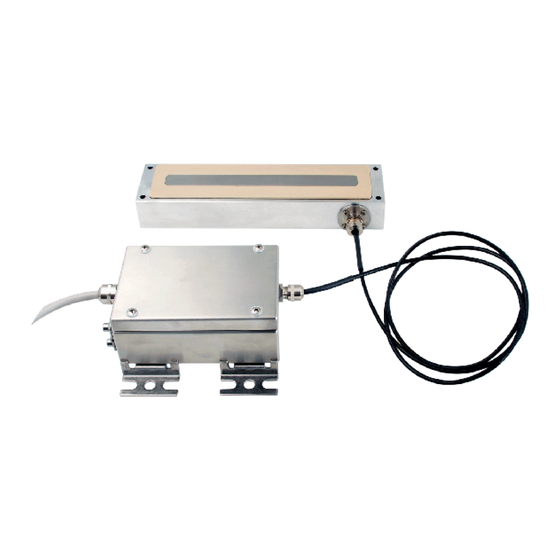
Page 22: Product Images
10 Product images Transmitter in stainless steel housing with SONO-GS1 probe... -
Page 23: Note
11 Note... - Page 24 Contact IMKO Micromodultechnik GmbH Am Reutgraben 2 76275 Ettlingen Germany Tel +49 7243 5921 0 Fax +49 7243 5921 40 info@imko.de www.imko.de/en...
Need help?
Do you have a question about the SONO-Ex GS1 and is the answer not in the manual?
Questions and answers