Table of Contents
Advertisement
Quick Links
Advertisement
Table of Contents

Related Manuals for IMKO SONO-VIEW


Summary of Contents for IMKO SONO-VIEW
- Page 1 Manual SONO-VIEW More Information: www.imko.de Moisture Sensor Experts...
- Page 2 Please refer to the information in this manual. If you have any questions, please contact IMKO service. Don’t open the device and please do not try to repair the device yourself - the guarantee expires when the device is opened or modified.
-
Page 3: Table Of Contents
Content General Notices ......................4 Intended Use ................................4 Temperatures and environmental conditions ......................4 Control Elements / Connections ................. 5 Control Elements ..............................5 Connections ................................5 Initial Commissioning ....................6 Safety Instructions ..............................6 Checking the Package Content for Completeness ....................6 Connection ................................6 Operation ........................ -
Page 4: General Notices
Intended Use This device was developed as a readout device for various IMKO probes. Only dedicated probes may be connected to this device. The connection of a probe not intended for this purpose can lead to the destruction of this device and / or the connected probe. -
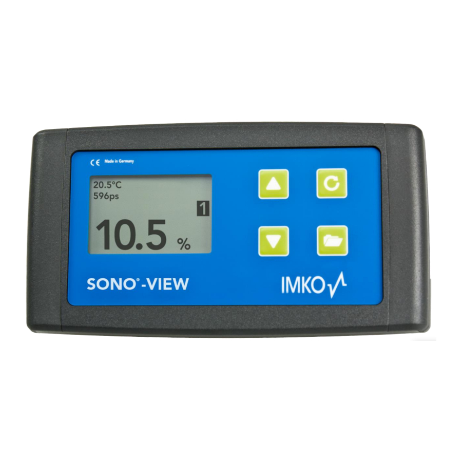
Page 5: Control Elements / Connections
Control Elements / Connections Control Elements Connections • USB (Type-Mini B) • USB-IMP-Bridge • Supply Voltage • Bus-Interface... -
Page 6: Initial Commissioning
+12..24V (RT) IMP-Bus (COM) IMP-Bus NOTE: The SONO-VIEW is suited for the display and configuration of up to eight probes. Should more than eight probes be connected, an error message will be generated, and the device cannot operate correctly. - Page 7 Connection example: Connection of the SONO-VIEW with two SONO probes and one joint voltage supply source.
-
Page 8: Operation
Start the installation process with the buttom In order to maintain the clarity within the administration of the probes, the SONO-VIEW operates on the basis of assigned probe numbers (1...8). These must be allocated to the detected serial numbers in the next step. -
Page 9: Measurement Value Display
In the event that only one probe is connected, the calibrated radar run-time is also presented. If more than one probe is connected to the SONO-VIEW, there is an option to change the display. For this purpose, press the buttons With each press, all connected probes are displayed one after the other as individual probes. -
Page 10: Settings
Settings Actuate the button while the measurement display is active and you will reach the setup menu. Here, you are enabled to perform various settings and call up information regarding the SONO-VIEW. The setup menu features the following structure: Setting... -
Page 11: Lcd Contrast
4.3.6 USB/IMP-Bridge As soon as this menu item is called up, the SONO-VIEW changes into a transparent data mode. All data packets will be now redirected from the USB interface directly on to the IMP-bus and vice versa. This enables a comfortable configuration of the probes via a connected PC without the necessity of additional hardware. -
Page 12: Probe Settings
NOTE: As long as the SONO-VIEW is in the USB-IMP-Bridge modus, no measurement values are queried by the probe. The probes however continue to measure and issue the measurement value at the analogue output. Actuate the button in order to exit the menu item „USB/IMP-Bridge“. -
Page 13: Sensor Info
4.4.1 Sensor Info If this menu item is selected, various information of the probe is called up and displayed. You can exit the menu item „Sensor Info” with the button 4.4.2 Material Calibration The menu item „Material Calibration“enables to adjust a material-specific calibration stored in the probe. This enables to significantly increase the accuracy of the measurement. -
Page 14: Change
4.4.2.2 Change The "CHANGE" sub-point allows you to perform a 1-point calibration or 2-point calibration. Use the buttons to switch between 1-point calibration and 2-point calibration. The corresponding procedure is executed with the key and the key is for finishing this procedure. 4.4.2.2.1 1-Point With this material calibration option, a linear equation (f(x)=mx+b) is calculated with the dry density, a reference moisture content and the tp value (transit time of the radar signal) which can be measured or set at the point of... - Page 15 After starting the measurement with the key mean value of 10 measured tp values is formed. During this phase, the SONO-View does not respond to any input. After completion of the measurement, the tp mean value is displayed.
-
Page 16: 2-Point
Set tp The tp value can be adjusted manually using the buttons. Press the button to accept the setting and press the button to move to the previous item. In the last step, the calibration settings can be saved with "Save" to the previously selected calibration memory location, or can be canceled with "Discard". - Page 17 Procedure: At the beginning of the calibration, the calibration memory (01 – 15) to be overwritten must be set using buttons. Press the button to accept the setting and press the Button to move to the previous item. Subsequently, the percentage moisture value at the lower point of the material to be measured, must be set with the buttons.
- Page 18 The percentage reference moisture of the upper point of the measured material, must then be set with the buttons. Press the button to accept the setting and press the button to move to the previous item. The next step is to determine the tp value (radar signal time), of the upper moisture value, by a measurement (with the connected probe) or by manual setting.
-
Page 19: Offset Balancing
You can exit this menu item with the button 4.4.4 Averaging Mode This menu item allows you to switch on or switch over a measurement averaging in the moisture probe. The IMKO moisture probes offer the following options: Mode CC: (Cyclic Cumulated) With automatic summation of a moisture quantity during one batch process. -
Page 20: Averaging Parameters
Mode CF: (Cyclic Floating Average) For continual average value with filtering and an accuracy of up to 0.1% for very slowly measuring processes, e.g. in fluidized bed dryers, conveyor belts, etc. NOTE: Please also refer to the information in your Probe User's Manual. Use the buttons to set the desired "Average Mode"... - Page 21 Averaging Mode Available Parameters Average Time Filter Upper Limit Offset Filter Lower Limit Offset CA – Cyclic Average Upper Limit Keep Time Lower Limit Keep Time Invalide Measure Count Average Time Filter Upper Limit Offset Filter Lower Limit Offset Upper Limit Keep Time Lower Limit Keep Time CK –...
-
Page 22: Basis Balancing
The parameters are dynamically enabled with the set „Average Parameter“. The buttons serve for the navigation between the individual parameters. The current value of the selected parameter is presented in the lower right section of the display. To change the value, press the button The value will now appear enlarged in the display. -
Page 23: Analog Parameter
Attention: In order to exclude the occurrence of a faulty air calibration, the sensor must be dry and free of any material during basic balancing. The notice „Please wait „will be generated in the display. The procedure lasts approximately 30 seconds. 4.4.7 Analog Parameter This menu is used to configure the analog output of the probe. -
Page 24: Technical Data
Technical Data Power Supply +12 .. 24V DC / 0.7W Operating Temperature 0 .. 50°C Dimensions 145mm x 75mm x 34 mm Weight 153g Mounting Cap Rail (optional) IMP-Bus Interfaces USB Mini-B (galvanically isolated) -
Page 25: Safety Notes
Intended Use Sensors and measuring systems of IMKO GmbH may only be used for the purpose described, taking into account the technical data. Misuse and use of the equipment other than for its intended purpose are not eligible. The... - Page 26 Danger by electricity The hand-held meter must not be immersed in water or other liquids. The sensor is insensitive to moisture contained in the typically measured products. Only connect the hand-held meter to a properly installed outlet with the supplied voltage supply cable, the voltage of which corresponds to the technical data. For the operation of this device, a power supply is required which must be located in the immediate environment or less than 3 meters and meets the following standards: DIN EN 61000-6-2 (interference immunity industry) and DIN EN 61000-6-4 (emission industry).
-
Page 27: Notes
Notes... - Page 28 Contact IMKO Micromodultechnik GmbH Am Reutgraben 2 76275 Ettlingen Germany Tel +49 7243 5921 0 Fax +49 7243 5921 40 info@imko.de www.imko.de/en...
Need help?
Do you have a question about the SONO-VIEW and is the answer not in the manual?
Questions and answers