
Related Manuals for Kontron PCI-755


Summary of Contents for Kontron PCI-755
- Page 1 PCI-755 Industrial Single Board Computer User’s Guide Rev. 1.40 September 2006 www.kontron.com.tw...
- Page 2 © 2006 Kontron, an International Corporation. All rights reserved. The information in this user’s guide is provided for reference only. Kontron does not assume any liability arising out of the application or use of the information or products described herein. This user’s guide may contain or reference information and products protected by copyrights or patents and does not convey any license under the patent rights of Kontron, nor the rights of others.
-
Page 3: Table Of Contents
Memory Module Installation ............3-7 PCI-755 User’s Guide... - Page 4 AT Power Mode using ATX Power ............6-3 PCI-755 User’s Guide...
- Page 5 Figure 1-2. PCI-755 Mechanical Dimensions........
- Page 6 PCI-755 User’s Guide...
- Page 7 Table 2-16. PCI-755 Rear Panel Connector Descriptions........
- Page 8 PCI-755 User’s Guide...
-
Page 9: Preface
Preface Contents How to Use This Guide ........ix Advisory Conventions. - Page 10 This page intentionally left blank. viii PCI-755 User’s Guide...
-
Page 11: How To Use This Guide
Chapter 4, BIOS Setup Information, specifies the meaning of each setup parameter and describes how to get advanced BIOS performance. Chapter 5, Driver Installation, provides information on installing installing the drivers for the PCI-755. Appendix A, System Resources, provides information on IRQ lines, DMA channels, memory and I/O... -
Page 12: Advisory Conventions
Disclaimer: We have tried to identify all situations that may pose a warning or caution condition in this user’s guide. However, Kontron does not claim to have covered all situations that might require the use of a Caution or Warning. -
Page 13: Unpacking
When unpacking, follow these steps: 1) After opening the box, save it and the packing material for possible future shipment. 2) Remove all items from the box. If any items listed on the purchase order are missing, notify Kontron customer service immediately. -
Page 14: Regulatory Compliance Statements
(take adequate measures) at their own expense. Changes or modifications not expressly approved by Kontron could void the user's authority to operate the equipment. Note: The assembler of a personal computer system may be required to test the... -
Page 15: Warranty Policy
Limitation of Liability In no event shall Kontron be liable for any defect in hardware, software, loss, or inadequacy of data of any kind, or for any direct, indirect, incidental, or consequential damages in connection with or arising out of the performance or use of any product furnished hereunder. -
Page 16: Maintaining Your Computer
Operating a system at a high altitude (low pressure) reduces the efficiency of the cooling fans to cool the system. This can cause electrical problems related to arcing and corona effects. This condition can also cause sealed components with internal pressure, such as electrolytic capacitors, to fail or perform at reduced efficiency. PCI-755 User’s Guide... -
Page 17: Power Protection
Surge protectors should be used with all UPS systems, and the UPS system should be Underwriters Laboratories (UL) safety approved. PCI-755 User’s Guide Maintaining Your Computer... - Page 18 This page intentionally left blank. PCI-755 User’s Guide...
-
Page 19: Safety Instructions
Safety Instructions Contents Before You Begin ........... xix When Working Inside a Computer . - Page 20 This page intentionally left blank. xviii PCI-755 User’s Guide...
-
Page 21: Before You Begin
Before You Begin Before handling the PCI-755, read the instructions and safety guidelines on the following pages to prevent damage to the product and to ensure your own personal safety. Refer to the “Advisories” section in the Preface for advisory conventions used in this user’s guide, including the distinction between Warnings, Cautions, Important Notes, and Notes. -
Page 22: When Working Inside A Computer
Also, before connecting a cable, make sure both connectors are correctly oriented and aligned. CAUTION Do not attempt to service the system yourself except as explained in this user’s guide. Follow installation and troubleshooting instructions closely. PCI-755 User’s Guide... -
Page 23: Preventing Electrostatic Discharge
Static electricity can harm system boards. Perform service at an ESD workstation and follow proper ESD procedure to reduce the risk of damage to components. Kontron strongly encourages you to follow proper ESD procedure, which can include wrist straps and smocks, when servicing equipment. - Page 24 This page intentionally left blank. xxii PCI-755 User’s Guide...
-
Page 25: Introduction
Chapter 1 Introduction Contents Overview ..........1-3 Checklist . - Page 26 This page intentionally left blank. PCI-755 User’s Guide...
-
Page 27: Overview
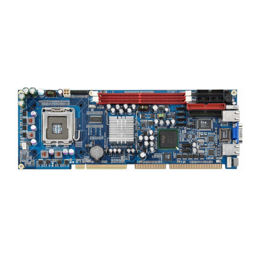
Overview The PCI-755 is a full-size PICMG 1.0 form factor single-processor system host board, based on the Intel® 915G chipset with ICH6 I/O Controller Hub. It features the new 90nm process Intel® Pentium® 4 Processor with LGA775 socket, 800MHz Front Side Bus, and 1MB L2 cache, and supports unbuffered, non-ECC, DDR2 DIMM 400/533MHz, up to 2 DIMMs up to 2GB. -
Page 28: Checklist
Checklist 1. Take out the PCI-755 unit from the carton box, check if the unit is properly secure in the plastic bag. 2. Check the contents of the carton box: PICMG 1.0 Single Board Computer ATA-66/100 HDD ribbon cable x1... -
Page 29: Product Specifications
One internal bi-direction parallel port with SPP/ECP/EPP mode One internal Floppy port Internal PS/2 Keyboard and Mouse port Watchdog Timer Two-stage watchdog timer Miscellaneous Voltage, fans and CPU/System temperature monitoring. Fan speed monitoring Table 1-1. PCI-755 Specifications PCI-755 User’s Guide Product Specifications... -
Page 30: Features
Features Chipset The PCI-755 is based on the Intel® 915G Graphics and Memory Controller Hub (GMCH) chipset with ICH6 I/O Controller Hub. A single Intel® Pentium® 4 (Celeron® D) Processor with LGA775 socket is supported with up to 800MHz front side bus. - Page 31 Flash-write protection will be implemented under software control Onboard Gigabit Ethernet Control The PCI-755 provides two 10/100/1000BASE-T Ethernet interfaces via two Marvell 88E8053 Ethernet Controllers. Two Marvell 88E8053 10/100/1000BASE-T Ethernet Controllers (PCI Express x1 Host Interface, functionality identical to PCI) Compliant to 802.3x flow control support...
- Page 32 Hardware Monitor The PCI-755 supports hardware monitoring via the IT8712F/IX Super I/O which provides temperature, fan, and voltage monitoring. It has analog-to-digital converters that allow software to monitor the voltages on the PCI-755. Please see Appendix A for detailed parameters.
-
Page 33: System Block Diagram
USB 2.0 PCI Bus USB 2.0 Fingers (Internal x4, External x1) PCI Bus 32-bit/33MHz BIOS FWH Golden IT8888 Fingers KB/Mouse ISA Bus LPT1/FDD IT8712F/IX LPC Super I/O COM1 COM2 Figure 1-1. PCI-755 System Block Diagram PCI-755 User’s Guide System Block Diagram... -
Page 34: Mechanical Dimensions
Mechanical Dimensions Figure 1-2. PCI-755 Mechanical Dimensions 1-10 PCI-755 User’s Guide... -
Page 35: Hardware Settings
Chapter 2 Hardware Settings Contents Overview ..........2-3 Jumpers . - Page 36 This page intentionally left blank. PCI-755 User’s Guide...
-
Page 37: Overview
This chapter provides the definitions and locations of jumpers, headers, and connectors. Jumpers The PCI-755 has several jumpers which must be properly configured to ensure correct operation.) Figure 2-1. Jumper Connector For a three-pin jumper (see Figure 2-1), the jumper setting is designated “1-2” when the jumper connects pins 1 and 2. -
Page 38: Jumper Settings And Pin Definitions
Jumper Settings and Pin Definitions Figure 2-2. Jumper and Connector Locations PCI-755 User’s Guide... -
Page 39: Jumper Settings
1-2 Shorted Disable 2-3 Shorted Table 2-2. BIOS Write Protect setting Clear CMOS setting (JP2: 3-pin 2.54mm pitch header) Function Normal (Default) 1-2 Shorted Clear CMOS 2-3 Shorted Table 2-3. Clear CMOS setting PCI-755 User’s Guide Jumper Settings and Pin Definitions... -
Page 40: Main Board Pin Assignments
Internal Keyboard Connector LPT connector SATA_1-4 Serial ATA Connectors SYS_TEMP System Temperature Connector USB1-2 USB Connectors Table 2-4. PCI-755 Main Board Connector Description ATX Power_12V Connector (ATX_POWER: 2x2 pin female) SIGNAL SIGNAL Ground +12V Ground +12V Table 2-5. ATX Power_12V Connector RS232 Serial Port Header (COM1-2: 5x2 box header 2.54mm pitch) - Page 41 #REDWC (#DENSITYSEL) #DS1 #INDEX #MOTOR A #DRIVE SELECT B #DRIVE SELECT A #MOTOR B #DIR #STEP #WRITE DATA #WRITE GATE #TRACK0 #WRITE PROTECT #READ DATA #SIDE1(#HEADSEL) #DISK CHANGE Table 2-8. Floppy Connector PCI-755 User’s Guide Jumper Settings and Pin Definitions...
- Page 42 PS_ON# IDE LED (+) +5VSB Power Button (+) PME# (Reverse) Power Button (-) Table 2-10. Front Panel Connector Note: To simulate AT power behaviour with an ATX power supply, +5VSB (standby) must be connected to Pin 9. PCI-755 User’s Guide...
- Page 43 ACK, Acknowledge Ground Busy Ground Paper Empty Ground Select Table 2-12. LPT Port Connector Serial ATA Connector (SATA1-4: 7-pin "L" type) SIGNAL SIGNAL SATA_TXP SATA_TXN SATA_RXN SATA_RXP Table 2-13. Serial ATA Connector PCI-755 User’s Guide Jumper Settings and Pin Definitions...
- Page 44 System Temperature Connector (SYS_TEMP: 2-pin 2.54mm pitch) SIGNAL System_Temp Table 2-14. System Temperature Connector USB Headers (USB1-2: 5x2-pin header 2.54mm pitch) SIGNAL SIGNAL USBD1- USBD2- USBD1+ USBD2+ “key” Table 2-15. USB0/1, USB2/3 Headers 2-10 PCI-755 User’s Guide...
-
Page 45: Rear Panel Pin Assignments
PS2 Mouse / Keyboard Connector LAN1-2 LAN1-2 (PCI Express x1 Port 1) 100/1000 Base-T Ethernet VGA Display Connector USB Connector Table 2-16. PCI-755 Rear Panel Connector Descriptions Keyboard/Mouse Connector (KB/MS: 6-pin purple Mini DIN) SIGNAL SIGNAL Keyboard data Mouse data... -
Page 46: Table 2-18. 10/100/1000 Base-Tx Ethernet Connectors
VGA Display Connector (VGA: D-Sub 15-pin female) SIGNAL SIGNAL Green Blue Ground Ground Ground Ground Ground DDCData HSync VSync DDCClk Table 2-19. VGA Display Connector USB Connector (USB: 4-pin Type A female) SIGNAL USB4 - USB4 + Table 2-20. USB4 Connector 2-12 PCI-755 User’s Guide... -
Page 47: System Installation
Chapter 3 System Installation Contents Overview ..........3-3 Processor Installation . - Page 48 This page intentionally left blank. PCI-755 User’s Guide...
-
Page 49: Overview
2) Align the gold triangle with the corner of the socket nearest the Load Lever that is trimmed at a 45 degree angle (see Figure 3-1). Carefully place the CPU into the socket body using a purely vertical motion. (Tilting the processor into place or shifting it into place on the socket can damage the sensitive socket contacts.) PCI-755 User’s Guide Overview... -
Page 50: Figure 3-1. Lga775 Cpu Socket
3) Verify that package is within the socket body and that the Orientation Keys are properly mated (see Figure 3-2). Gold Triangle Corner trimmed at 45 degrees Orientation Keys Orientation Keys Figure 3-2. CPU Alignment in LGA775 Socket PCI-755 User’s Guide... -
Page 51: Figure 3-3. Cpu Secured In Lga775 Socket
3) Remove the CPU by grasping the substrate edges only with thumb and forefinger and lifting it out with a purely vertical motion. 4) Replace the protective cover. WARNING The CPU and the heatsink may be hot and could cause burns. PCI-755 User’s Guide Processor Installation... - Page 52 Important: Make sure that good thermal contact is made between the processor and heat sink. Insufficient contact or incorrect use of heat sink, fan, or thermal compound can cause the processor to overheat, which may crash the system or cause permanent damage to the CPU. PCI-755 User’s Guide...
-
Page 53: Memory Module Installation
2) Do not touch the connectors of the DIMM. Dirt or other residue may cause a malfunction. 3) Hold the DIMM with its notch aligned with the memory socket of the PCI-755 and insert it completely into the socket. Lift the locking tabs at each end of the DIMM socket to lock it in position. - Page 54 To remove the DIMM, use your fingers or a small screwdriver to carefully push away the plastic tabs that secure the DIMM at each end. Lift it out of the socket. Make sure you store the DIMM in an anti-static bag. The socket must be populated with memory modules of the same size and manufacturer. PCI-755 User’s Guide...
- Page 55 Chapter 4 Award BIOS Setup Contents Overview ..........4-3 Determining the BIOS Version .
- Page 56 This page intentionally left blank. PCI-755 User’s Guide...
- Page 57 This chapter provides a generic description of the Award BIOS. The BIOS setup menus and available selections will vary from those of your product. For specific information on the BIOS for your product, please contact Kontron. Note: The BIOS menus and selections for your product will vary from those in this chapter.
- Page 58 This page intentionally left blank. PCI-755 User’s Guide...
-
Page 59: Table 4-1. Main Menu
Use this menu to change the values in the chipset registers and optimize your system's performance. Integrated Peripherals: Use this menu to specify your settings for integrated peripherals. Power Management Setup: Use this menu to specify your settings for power management. PCI-755 User’s Guide Main Menu... - Page 60 Supervisor / User Password:: Use this menu to set User and Supervisor Passwords. Save & Exit Setup: Save CMOS value changes to CMOS and exit setup. Exit Without Save: Abandon all CMOS value changes and exit setup. PCI-755 User’s Guide...
-
Page 61: Table 4-2. Standard Cmos Features
Press <Enter> to enter the sub-menu and select detailed options. IDE Channel 0/1 Slave: Options are available in the sub-menu (described in the IDE Adapters section below) Press <Enter> to enter the sub-menu and select detailed options. PCI-755 User’s Guide Standard CMOS Features... - Page 62 Base Memory: Options- N/A Displays the amount of conventional memory detected during boot. Extended Memory: Options- N/A Displays the amount of extended memory detected during boot. Total Memory: Options- N/A Displays the total memory available on the system. PCI-755 User’s Guide...
-
Page 63: Table 4-3. Ide Primary Master
Choose the access mode for this hard disk Capacity: Options- Auto Display your disk drive size Disk drive capacity (approximate). Note that this size is usually slightly greater than the size of a formatted disk given by a disk-checking program. PCI-755 User’s Guide Standard CMOS Features... - Page 64 Options- Min = 0, Max = 65535 **** Warning: Setting a value of 65535 means no hard disk! Landing zone: Options- Min = 0, Max = 65535 Sector: Options- Min = 0, Max = 255 Number of sectors per track 4-10 PCI-755 User’s Guide...
-
Page 65: Table 4-4. Advanced Bios Features
Disabled---No warning message will appear when anything attempts to access the boot sector or hard disk partition table. Hyper-Threading Technology: This option will enable or disable the Hyper-Threading Technology function of the CPU. PCI-755 User’s Guide Advanced BIOS Features 4-11... - Page 66 <Enter> to disable security. Once security is disabled, the system will boot and you can enter Setup freely. APIC Mode: This item enables or disables the Advanced Programmable Interrupt Controller (APIC) feature. 4-12 PCI-755 User’s Guide...
-
Page 67: Table 4-5. Advanced Chipset Features
This selection provides the option to select DRAM timing detection using Serial Presence Detect (SPD) or by manually setting it. Options- Manual, By SPD. CAS Latency Time: When synchronous DRAM is installed, the number of clock cycles of CAS latency depends on the DRAM timing. Options- 2, 2.5. PCI-755 User’s Guide Advanced Chipset Features 4-13... - Page 68 System Memory Frequency: This item allows you to determine the system memory frequency. **On-Chip VGA Setting** Init Display First: This item allows you to decide whether to first activate the PCI slot, PCI Express Slot, or on-chip VGA. 4-14 PCI-755 User’s Guide...
-
Page 69: Table 4-6. Integrated Peripherals
** On-Chip Serial ATA Setting ** On-Chip Serial ATA [Enabled] ↑↓→←Move Enter: Select +/-/PU/PD: Value F10: Save ESC: Exit F1: General Help F5: Previous Values F6: Fail-safe defaults F7: Optimized Defaults Table 4-7. OnChip IDE Device PCI-755 User’s Guide Integrated Peripherals 4-15... - Page 70 DMA driver (Windows 95 OSR2 or a third-party IDE bus master driver). If your hard drive and your system software both support Ultra DMA/33, select "Auto" to enable BIOS support. Options- Auto, Disabled. On-Chip Serial ATA: This item allows you to enable or disable the On-Chip Serial ATA. 4-16 PCI-755 User’s Guide...
-
Page 71: Table 4-8. Onboard Device
Allows you to enable or disable the LAN function. Onboard LAN Boot ROM: Allows you to enable or disable the Onboard LAN Boot ROM function. Watchdog Timer Select: Allows you to enable or disable the Watchdog Timer function. PCI-755 User’s Guide Integrated Peripherals 4-17... -
Page 72: Table 4-9. Superio Device
Select a DMA channel for the parallel port for use during ECP mode. Options- 3, 1. PWRON After PWR-Fail: This field sets the system power status whether on or off when power returns to the system from a power failure situation. 4-18 PCI-755 User’s Guide... -
Page 73: Table 4-10. Power Management Setup
S3 (STR): Suspend to RAM S1 & S3: POS + STR Run VGABIOS if S3 Resume: Choosing Enabled will run VGA BIOS to initialize the VGA card when system wakes up from S3 state. PCI-755 User’s Guide Power Management Setup 4-19... - Page 74 Suspend Type: Select the Suspend Type. Options- PWRON Suspend, Stop Grant. Suspend Mode: When "Enabled" and a set time of system inactivity has elapsed, all devices except the CPU will be shut off. Options- Enabled, Disabled. 4-20 PCI-755 User’s Guide...
- Page 75 Configures the power button function: Instant-Off: The power button functions as a normal power-on/-off button. Delay 4 Sec: The system is turned off if the power button is pressed for more than four seconds. PCI-755 User’s Guide Power Management Setup 4-21...
-
Page 76: Table 4-11. Pnp/Pci Configurations
This item allows you to automatically configure all the boot- and Plug and Play-compatible devices. If you select Auto, all the interrupt request (IRQ) and DMA assignment fields are cleared, as the BIOS automatically assigns them. 4-22 PCI-755 User’s Guide... -
Page 77: Table 4-12. Pc Health Status
Options- Disabled, 60°C / 140°F, 65°C / 149°F, 70°C / 159°F and 75°C / 167°F. VCore/3.3V/+5V/12V/+5VSB/Voltage Battery: Detect the system¡¦s voltage status automatically. SYS/CPU Temperature: Shows the current CPU temperature. CPU Fan Speed: This field displays the current CPU FAN speed. PCI-755 User’s Guide PC Health Status 4-23... -
Page 78: Table 4-13. Frequency/Voltage Control
When disabled, it will send the clock signal to the PCI slot. Options- Enabled, Disabled. Spread Spectrum Modulated: This item allows you to enable or disable the Spread Spectrum Modulated. Options- Disabled, -0.25%, -0.50% and -0.75%. 4-24 PCI-755 User’s Guide... -
Page 79: Load Optimized Defaults
Security option is set to "System", a password will be required both at boot and on entry into Setup. If set to "Setup", a password is required only when trying to enter Setup. PCI-755 User’s Guide Load Optimized Defaults... -
Page 80: Exit Selection
Pressing <Enter> on this item asks for confirmation: Quit without saving (Y/N)? Y This allows you to exit Setup without storing any changes in CMOS. The previous selections remain in effect. This exits the Setup utility and restarts your computer. 4-26 PCI-755 User’s Guide... - Page 81 Chapter 5 Driver Installation Contents Overview ..........5-3 Chipset Driver Installation .
- Page 82 This page intentionally left blank. PCI-755 User’s Guide...
- Page 83 Overview This chapter provides information on installing the necessary drivers for the PCI-755. The following sections describe driver installation procedures for Windows operating systems. Download the drivers from the Kontron website and install them in the order they are listed below. For other operating systems, please contact Kontron.
- Page 84 This page intentionally left blank. PCI-755 User’s Guide...
- Page 85 Appendix A System Resources Contents Interrupt Request (IRQ) Lines ....... . . 6-3 DMA Channels .
- Page 86 This page intentionally left blank. PCI-755 User’s Guide...
-
Page 87: Table A-1. Irq Assignments
Unavailable if LPT used in ECP mode. Cascade Sound Note (1) free free Table A-2. DMA Assignments Note: If the "Used For" device is disabled in setup, the corresponding interrupt is available for other devices. PCI-755 User’s Guide Interrupt Request (IRQ) Lines... -
Page 88: Table A-3. Memory Mapping
EGA / VGA CGA/CRT Register, Controller and 3D4h – 3D9h Palette Register 3F0h – 3F7h Floppy Diskette 3F6h, 3F7h Enhanced IDE 3F8h – 3FFh COM1 0CF8h PCI Configuration Register/address 0CFCh PCI Configuration Register/data Table A-4. I/O Address Map PCI-755 User’s Guide... -
Page 89: Table A-5. Pci Devices
AD29 Slot 4 INTE AD28 P2I Bridge AD22 Table A-5. PCI Devices Inter-IC Bus (I I2C Address Used For Comment DDR2-RAM DIMM Socket 0 Address DDR2-RAM DIMM Socket 1 Address Table A-6. Inter-IC Bus (I PCI-755 User’s Guide PCI Devices... -
Page 90: Table A-7. Hardware Monitor Parameters
+/- 5% SYS_TEMP System_Temperature PWM_TEMP PWM_Temperature CPU_TEMP CPU_Temperature PRDCHOT# CPU over temperature shutdown output CPUFANIN CPU Fan Fan Tachometer input CPUFANOUT CPU Fan DC/PWM Fan output control BEEP Beep function for hardware monitor Table A-7. Hardware Monitor Parameters PCI-755 User’s Guide... - Page 91 Appendix B AT Power Mode Contents AT Power Mode using ATX Power ....... . 6-3...
- Page 92 This page intentionally left blank. PCI-755 User’s Guide...
- Page 93 In order to simulate AT power behaviour using an ATX power supply, +5VSB (standby) must be connected to Pin 9 of the Front Panel Connector (J1). See Figure 2-2. Jumper and Connector Locations (p. 2-4) for the connector location and Table 2-10. Front Panel Connector (p. 2-8) for the pin definition. PCI-755 User’s Guide AT Power Mode using ATX Power...
- Page 94 PCI-755 User’s Guide...
Need help?
Do you have a question about the PCI-755 and is the answer not in the manual?
Questions and answers