
Related Manuals for Kontron COMe Ref. Carrier-i T10 TNI Series


Summary of Contents for Kontron COMe Ref. Carrier-i T10 TNI Series
- Page 1 » User Guide « COMe Ref. Carrier-i T10 TNIx Doc. ID: 1060-3229, Rev. 1.2 Date: April 19, 2017 The pulse of innovation...
-
Page 2: Revision History
Disclaimer Copyright © 2016 Kontron AG. All rights reserved. All data is for information purposes only and not guaranteed for legal purposes. Information has been carefully checked and is believed to be accurate; however, no responsibility is assumed for inaccuracies. Kontron and the Kontron logo and all other trademarks or registered trademarks are the property of their respective owners and are recognized. -
Page 3: Table Of Contents
SATA Interfaces ..................20 2.3.3 Gigabit Ethernet Interfaces ................20 2.3.4 USB 2.0 Interfaces ..................21 2.3.5 USB 3.0 Interfaces ..................21 2.3.6 HD Audio Interfaces ..................21 2.3.7 UART Interfaces..................22 2.3.8 GPIO/SDIO Interfaces .................. 22 2.3.9 microSD/SIM Interface................. 23 www.kontron.com... - Page 4 COMe Ref. Carrier-i T10 TNIx 2.3.10 SYS_Signals / Embedded Interfaces ..............23 2.3.11 CPU Fan Interface ..................24 2.3.12 Front Panel Interface ................... 24 2.3.13 DIP Switch ....................25 2.3.14 Power Supply and Management ..............26 2.3.15 RTC......................26 www.kontron.com...
-
Page 5: Tables
GPIO Pin Header J11 ................... 22 Pin Header J6 ....................23 PWM Fan Connector J2 ..................24 Front Panel Connector J5 Pinout ................24 DIP Switch SW1 Functionality ................25 Power Connector J19 Pinout ................. 26 Smart Battery Connector J3 Pinout ................ 26 www.kontron.com... -
Page 6: Figures
GPIO Pin Header J11 ..................22 Pin Header J6 ....................23 PWM Fan Connector J2 ..................24 Front Panel Connector J5 ..................24 DIP Switch SW1 ....................25 Power Connector J19 ..................26 Smart Battery Connector J3 ................. 26 www.kontron.com... -
Page 7: Warranty
Warranty This Kontron product is warranted against defects in material and workmanship for the warranty period from the date of shipment. During the warranty period, Kontron will at its discretion decide to repair or replace defective products. Within the warranty period, the repair of products is free of charge as long as warranty conditions are observed. -
Page 8: Introduction
GBLan0 (Module) GBLan1 (Carrier) SATA0 USB 2.0 / 3.0 I/O USB 2.0 Header HDA Codec Line-In/Out S/PDIF SER0 GPIO microSD/SIM Sys Signals Sys Panel CPU Fan RTC connector Goldcap 1.5F SMART Battery 12V Input 6.5 - 30V Input Rubber Feet www.kontron.com... -
Page 9: Board Diagrams
GPIO Header SATA #1 GPIO Switch GPIO/SDIO SATA µSD Card SATA #0 SDIO Ethernet GBE#0 Power 5V_SB 6.5-30V Ethernet GBE#1 PCIe #2 I/O Power to 7.2V SMART Battery Peripherals IO Shield Component Configuration Internal connector jumper or pin header www.kontron.com... -
Page 10: Rear Panel
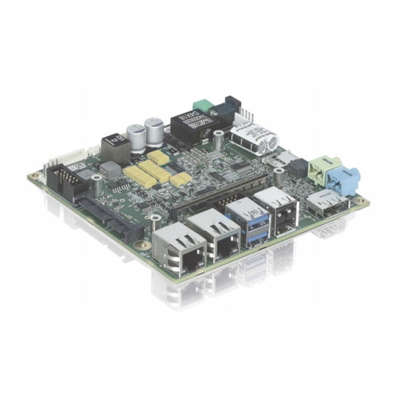
User Guide COMe Ref. Carrier-i T10 TNI 1.2.2 Rear Panel Figure 2: COMe Ref. Carrier-i T10 TNI Rear Panel miniDP DisplayPort 3.0/2.0 1.2.3 Board Layout Figure 3: COMe Ref. Carrier-i T10 TNI Layout - Top View C181 B110 A110 www.kontron.com... -
Page 11: Come Ref. Carrier-I T10 Tni Layout - Bottom View
User Guide COMe Ref. Carrier-i T10 TNI Figure 4: COMe Ref. Carrier-i T10 TNI Layout - Bottom View www.kontron.com... -
Page 12: Component Overview
Mini PCIe card slot (full-size) / mSATA socket Mini PCIe card latch (half-size) Mini PCIe card slot (half-size) DIP switch Carrier EEPROM (FRUPROM) Intel® Ethernet Controller I210-IT Smart Battery Controller TI BQ24725A HD Audio Codec IDT / Tempo Semi 92HD73C www.kontron.com... -
Page 13: Technical Specification
» S/PDIF header, J24 UART One RS-232 COM por t (RX/TX only) via pin header, J8 (COM1/SER0) GPIO/SDIO Either four GPIs and four GPOs via the 10-pin GPIO pin header, J11, or alternatively SDIO usage via microSD/SIM combo socket www.kontron.com... - Page 14 93% RH at 40 °C, non-condensing (acc. to IEC 60068-2-78) Form Factor COM Express® carrier, pinout Type 10, Thin-nITX form factor Dimensions 120 mm x 120 mm (nITX) Max. component height: Top side: 16.5 mm Bottom side: 4.0 mm www.kontron.com...
-
Page 15: Accessories
18 bit LVDS to DVI conver ter 9-5000-0353 ADA-LVDS_DVI 24 bit 24 bit LVDS to DVI converter 96006-0000-00-8 ADA-DP-LVDS DP to LVDS adapter 96082-0000-00-0 KAB-ADAPT-DP-DVI DP to DVI adapter cable 96083-0000-00-0 KAB-ADAPT-DP-VGA DP to VGA adapter cable 96084-0000-00-0 KAB-ADAPT-DP-HDMI DP to HDMI adapter cable www.kontron.com... -
Page 16: Standards
Boards without conformal coating must not be exposed to a change of temperature which can lead to condensation, as it may cause irreversible damage especially when the board is powered up again. Kontron does not accept any responsibility for damage to products resulting from destruc- tive environmental testing. www.kontron.com... -
Page 17: Related Publications
SD Spec. Part E1 SDIO Spec. Version 2.00 SD Spec. Part 2 File System Spec. Version 3.00 SD Spec. Part 1 Physical Layer Spec. Version 3.00 I2C Bus Specif ication Version 4.0 SMBus SMBus Specif ication Version 2.0 ACPI ACPI spec Rev 5.0 www.kontron.com... -
Page 18: Functional Description
2 . 2 G r a p h i c s I n te r fa c e s 2.2.1 Digital Display Inter faces The COMe Ref. Carrier-i T10 TNI provides the following digital display interface (DDI): » DDI0 from the COMe module is directly mapped to the DisplayPort++ connector, J17 www.kontron.com... -
Page 19: Lvds/Edp Interface
If eDP support is required, the COMe Ref. Carrier-i T10 TNI may optionally be equipped with a Mini Dis- playPort++ connector, J16, instead of the LVDS/JILI connector, J15. Note: In order to use the eDP interface, the COMe module installed must also support eDP. www.kontron.com... -
Page 20: System Interfaces
ACT (off) + LINK(on): 10BASE-T Ethernet Speed Note: The RJ45 Ethernet connector, J7, and the Intel® Ethernet Controller I210-IT, U23, are available as a standard feature on the COMe Ref. Carrier-i T10 TNIV (Value) and the COMe Ref. Carrier-i T10 TNIP (Professional) versions. www.kontron.com... -
Page 21: Usb 2.0 Interfaces
The COMe Ref. Carrier-i T10 TNI provides HD Audio via the industrial grade HD Audio Codec IDT / Tempo Semi 92HD73C (U29) through the following analog and digital audio connectors: » Rear panel line-in connector, J22 » Rear panel SPK / line-out connector, J23 » S/PDIF header, J24 www.kontron.com... -
Page 22: Uart Interfaces
The COMe Ref. Carrier-i T10 TNI provides four GPIs and four GPOs via a 10-pin GPIO pin header, J11. The following figure and table provide pinout information for the GPIO pin header J11. Figure 9: GPIO Pin Header J11 Table 11: GPIO Pin Header J11 SIGNAL GPO3 GPO2 GPO1 GPO0 GPI3 GPI2 GPI1 GPI0 VCC 3.3V www.kontron.com... -
Page 23: Microsd/Sim Interface
» Watchdog » » SLEEP The following figure and table provide pinout information for the pin header J6. Figure 10: Pin Header J6 Table 12: Pin Header J6 SIGNAL THRM# LPC_SERIRQ SLEEP# LID# WAKE1# SMB_ALERT# SMB_DAT SMB_CK I2C_DAT I2C_CK www.kontron.com... -
Page 24: Cpu Fan Interface
Speaker -out (Beep) The following figure and table provide pinout information for the front panel connector J5. Figure 12: Front Panel Connector J5 Table 14: Front Panel Connector J5 Pinout SIGNAL SIGNAL BEEP# SYS_RESET# BEEP+ PWRBTN# ATA_ACT# Power_LED+ HDD_LED+ www.kontron.com... -
Page 25: Dip Switch
Disable 5V standby power to USB ports USB#[2;3] for wake events Enable booting from COMe module SPI Flash Disable booting from COMe module SPI Flash-Carr ier BIOS enabled Wireless disable for Mini PCIe Wireless enable for Mini PCIe The default setting is indicated by using italic bold. www.kontron.com... -
Page 26: Power Supply And Management
The COMe Ref. Carrier-i T10 TNI provides a 2-pin connector, J14, for an external CMOS battery. In ad- dition, the COMe Ref. Carrier-i T10 TNIV (Value) and the COMe Ref. Carrier-i T10 TNIP (Professional) ver- sions provide a 1.5F goldcap, C181, for RTC backup. www.kontron.com... - Page 27 Tel.: + 49 (0) 821 / 4086 0 Tel.: + 1 888 294 4558 Tel.: + 86 10 63751188 Fax: + 49 (0) 821 / 4086 111 Fax: + 1 858 677 0898 Fax: + 86 10 83682438 info@kontron.com info@us.kontron.com info@kontron.cn www.kontron.com...
- Page 28 Mouser Electronics Authorized Distributor Click to View Pricing, Inventory, Delivery & Lifecycle Information: Kontron 34105-0000-00-0 34105-0000-00-1...
Need help?
Do you have a question about the COMe Ref. Carrier-i T10 TNI Series and is the answer not in the manual?
Questions and answers