Table of Contents
Advertisement
Quick Links
Advertisement
Table of Contents

Related Manuals for Kontron COMe-cAP6


Summary of Contents for Kontron COMe-cAP6
- Page 1 USER GUIDE COMe-cAP6 User Guide Rev. 1.0...
-
Page 2: Table Of Contents
COMe-cAP6 User Guide Table of Contents 1. General Information ........................1.1 Disclaimer ..........................1.2 Intended Use ........................... 1.3 Terms and Conditions ......................1.4 Customer Support ........................1.5 Customer Service ........................1.6 Customer Comments ......................1.7 Symbols ............................ 1.8 For Your Safety ........................ - Page 3 3.7 Thermal Management ......................3.7.1 Heatspreader Plate Assembly .................... 3.7.2 Active/Passive Cooling Solutions ..................3.7.3 Operating with Kontron Heatspreader Plate (HSP) Assembly ..........3.7.4 Operating without Kontron Heatspreader Plate (HSP) Assembly ........3.7.5 Temperature Sensors ......................3.7.6 On-Module Fan Connector ....................
- Page 4 COMe-cAP6 User Guide 5.7 Firmware Update ........................6. Technical Support ........................6.1 Warranty ..........................6.2 Returning Defective Material ..................... 7. Document Revision ........................www.kontron.com...
-
Page 5: General Information
1. General Information 1.1 Disclaimer Kontron would like to point out that the information contained in this user guide may be subject to alteration, particularly as a result of the constant upgrading of Kontron products. This document does not entail any guarantee on the part of Kontron with respect to technical processes described in the user guide or any product characteristics set out in the user guide. -
Page 6: Intended Use
PHYSICAL OR ENVIRONMENTAL DAMAGE (COLLECTIVELY, “HIGH RISK APPLICATIONS”). You understand and agree that your use of Kontron devices as a component in High Risk Applications is entirely at your risk. To minimize the risks associated with your products and applications, you should provide adequate design and operating safeguards. -
Page 7: Terms And Conditions
Kontron sells products worldwide and declares regional General Terms & Conditions of Sale, and Purchase Order Terms & Conditions. Visit https://www.kontron.com/terms-and-conditions. For contact information, refer to the corporate offices contact information on the last page of this user... -
Page 8: Symbols
COMe-cAP6 User Guide 1.7 Symbols The following symbols may be used in this user guide of COMe-cAP6 simple Box Info-Box Important-Box Alert-Box Tip-Box Help-Box Todo-Box Download-Box www.kontron.com 4/67... -
Page 9: For Your Safety
COMe-cAP6 User Guide 1.8 For Your Safety Your new Kontron product was developed and tested carefully to provide all features necessary to ensure its compliance with electrical safety requirements. It was also designed for a long fault-free life. However, the life expectancy of your product can be drastically reduced by improper treatment during unpacking and installation. -
Page 10: Lithium Battery Precautions
Dispose of used batteries according to the manufacturer’s instructions. 1.12 General Instructions on Usage In order to maintain Kontron’s product warranty, this product must not be altered or modified in any way. Changes or modifications to the product, that are not explicitly approved by Kontron and described in this user guide or received from Kontron Support as a special handling instruction, will void your warranty. -
Page 11: Quality And Environmental Management
COMe-cAP6 User Guide 1.13 Quality and Environmental Management Kontron aims to deliver reliable high-end products designed and built for quality, and aims to complying with environmental laws, regulations, and other environmentally oriented requirements. For more information regarding Kontron’s quality and environmental responsibilities, visit https://www.kontron.com/en/quality-management. -
Page 12: Introduction
2.5 Gbit Ethernet. As storage medium, a NVME SSD up to 1 TB can be optionally integrated onboard. The COMe-cAP6 is ideally suited as a powerful successor for existing solutions, as it takes over their pin assignment and feature implementation. Typical applications include communication, digital signage, professional gaming and entertainment, medical imaging, surveillance and security, industrial edge computing as well as industrial plant-, machine- and robot-control at the shop floor... -
Page 13: Com Express® Documentation
2.4 COM Express® Functionality All Kontron COM Express® compact modules contain two 220-pin connectors, each of which has two rows called row A & B on the primary connector and row C & D on the secondary connector. The COM Express®... -
Page 14: Com Express® Benefits
COM Express® defines a Computer-On-Module (COM), with all the components necessary for a bootable host computer, packaged as a highly integrated computer. All Kontron COM Express® modules are very compact and feature a standardized form factor and a standardized connector layout that carry a specified set of signals. -
Page 15: Product Specification
COMe-cAP6 User Guide 3. Product Specification 3.1 Module Variants The COMe-cAP6 is available in different processor, memory and temperature variants to cover demands in performance, price and power. 3.1.1 Commercial Grade Modules (0°C to +60°C) Part Number Product Name Description COM Express®... -
Page 16: Industrial Temperature Grade Modules (E2, -40°C To +85°C)
13 Generation Intel® Core™ technology. 3.2 Accessories Accessories are product specific, COMe-type 6 specific or general COMe accessories. For more information, contact your local Kontron Sales Representative or Kontron Inside Sales. Part Number Carrier Description 38116-0000-00-0 COMe Eval Carrier2 T6 COM Express®... -
Page 17: Functional Specification
COMe-cAP6 User Guide 3.3 Functional Specification 3.3.1 Technical Data Function Definition Compliance COM Express® Compact Pin-out Type 6 Dimension 95 x 95 mm (H X W) Intel® 12 Generation Core™ family: Core™ i7-12800HE, Core™ i5-12600HE, Core™ i3-12300HE, Processors Core™ i7-1270PE, Core™ i5-1250PE, Core™ i3-1220PE, Core™... -
Page 18: Block Diagram
COMe-cAP6 User Guide 3.3.2 Block Diagram www.kontron.com 14/67... -
Page 19: Front View
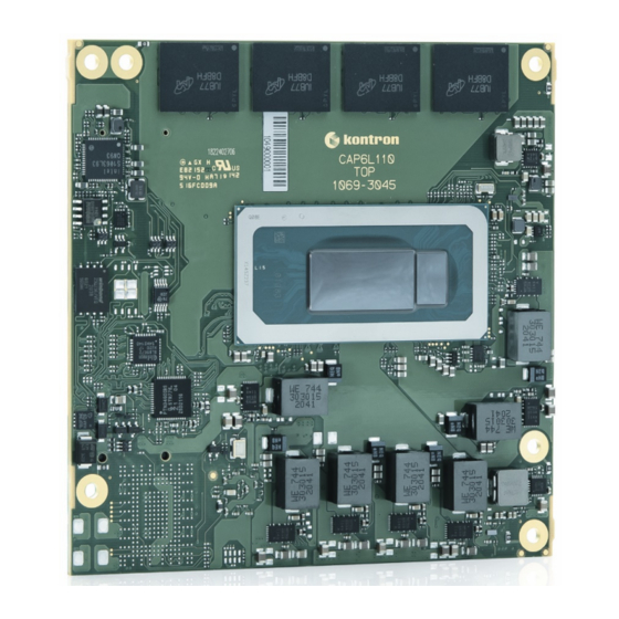
COMe-cAP6 User Guide 3.3.3 Front View Figure 2: Front View COMe-cAP6 SoC - Processor (CPU) & Chipset (PCH) LPDDR5 memory down Optional NVMe SSD www.kontron.com 15/67... -
Page 20: Rear View
COMe-cAP6 User Guide 3.3.4 Rear View Figure 3: Rear View COMe-cAP6 COMe connectors Embedded Controller 3-pin fan connector www.kontron.com 16/67... -
Page 21: Processor (Cpu)
COMe-cAP6 User Guide 3.3.5 Processor (CPU) 12th Gen Intel® Core™ mobile processors are the first Intel® Core™ processors to feature performance hybrid architecture with Intel® Thread Director. This innovative new chip design combines Performance-cores (P-cores) that focus on primary workloads with Efficient-cores (E-cores) that are built for multitasking. -
Page 22: Plattform Controller Hub (Pch)
COMe-cAP6 User Guide Max P- Max E- Number Intel® P-Core E-Core Number Number Number Core Core Intel Processor Processor Smart Base Base Processor of P- of E- Turbo Turbo Execution vPro® Number Cores Cache Freq Freq Graphics cores cores Threads... -
Page 23: System Memory
COMe-cAP6 User Guide 3.3.7 System Memory The COMe-cAP6 uses a Dual-Channel LPDDR5 memory down configuration with up to 4 x32 chips which enables a maximum system memory capacity of 64 GByte. Depending on the internal structure of used RAM chips a maximum transfer rate of 5200 MT/s can be achieved. ECC as well as IBECC (In- Band error-correcting code) isn't supported by the integrated PCH of the 12th Gen Intel®... -
Page 24: Interfaces
PCI Express Graphics 4.0 (PEG) In addition to the PCIe Gen3 lanes provided by the On-Package PCH, up to 16 additional PCIe Gen4 lanes are provided by the CPU which are routed to the PEG ports on the COMe-cAP6. COMe Supported Lane Configuration... -
Page 25: Universal Serial Bus (Usb)
Therefore, the number of available USB 2.0 only ports decreases with every used USB 3.2 Gen 1 or Gen 2 port. The COMe-cAP6 offers four USB 3.2 Gen 2 ports with 10 Gb/s (including USB 2.0) and four dedicated USB 2.0 ports. -
Page 26: Serial Ata (Sata)
COMe-cAP6 User Guide 3.4.3 Serial ATA (SATA) COM Express® Type 6 modules support up to four SATA ports. The COMe-cAP6 offers two SATA Gen 3 ports with 6 Gb/s. COMe PCH HSIO Lane# HSIO Type Description SATA0 10 SATA 0... - Page 27 LVDS (default), eDP (option) Table 16: COMe-cAP6 Graphics Interfaces Kontron recommends only using a DP-to-HDMI or DP-to-DVI passive adapter that is compliant to the DP Dual-Mode standard. If adapters are used with FET level shifter for DCC translation, display detection issues may occur.
-
Page 28: Audio Interfaces
“console redirect” features available in many operating systems. On the COMe-cAP6 both serial ports are provided via PCIe by the On-Package PCH by default. For Windows/Linux appropriate drivers are delivered by the corresponding OS Board Support Package (BSP) stored on Kontron’s Customer... -
Page 29: General Purpose Spi Interface
(CS) lines. On COMe-cAP6 SPI0 is routed to the COMe connector. The SPI interface may only be used with a serial flash device on the carrier board to boot an external BIOS firmware. -
Page 30: I2C
COMe-cAP6 User Guide The module will not boot up if module and carrier configuration do not match. COMe Connector Pin LPC Mode Connection (from CPLD) eSPI mode connection (from PCH) B[4:7] LPC_AD[0:3] ESPI_IO_[0:3] LPC_FRAME# ESPI_CS0# LPC_CLK ESPI_CK B[8:9] LPC_DRQ[0:1] ESPI_ALERT[0:1]#... -
Page 31: General Purpose Ios (Gpios)
COMe-cAP6 User Guide 3.4.12 General Purpose IOs (GPIOs) The COMe-cAP6 offers 8 GPIOs, generated by the onboard CPLD, on the dedicated COM Express® pins. The type of termination resistor used sets the direction of the GPIO, where GPI terminations are pull-up resistors, and GPO terminations are pull-down resistors. -
Page 32: Features
Table 23: ACPI Power States Function Not all ACPI defined power states are available. The COMe-cAP6 supports ACPI 6.0 and the power states S0, S3, S4, S5 only. Systems that support the low-power idle state do not use power states S3 and S4. -
Page 33: Embedded Controller - Hardware Monitor
FAN control onboard as well as to COMe. The HWM is accessible via the SMBus, see chapter 3.4.13. 3.5.3 Trusted Platform Module (TPM) The COMe-cAP6 supports a TPM chip which is directly connected to SPI0 (dedicated SPI interface from On-Package PCH). 3.5.4 Watchdog Timer (WDT) The watchdog timer interupt is a hardware or software timer implemented by the module to the carrier board if there is a fault condition in the main program;... -
Page 34: Real-Time Clock (Rtc)
The COMe-cAP6 supports typical RTC values of 3 V and less than 10 μA. When powered by the main power supply on-module regulators generate the RTC voltage, to reduce RTC current draw. The RTC’s battery voltage range is 2.8 V to 3.47 V. -
Page 35: Boot Spi Device
SPI Flash. The COMe-cAP6 supports on-module and carrier boot from SPI. It does not support Slave Attached File Sharing (SAFS) configurations (i.e. BIOS can’t be attached to eSPI via an Embedded Controller/Board Management Controller). -
Page 36: Embedded Eeprom
COMe-cAP6 User Guide 3.5.8 Embedded EEPROM The module's 32 kbit serial EEPROM (formerly known as JIDA EEPROM) device is attached to the I2C bus (I2C_EXT) from the CPLD and accessible via I2C bus 8-bit address 0x0A (see chapter 3.4.11). 3.6 Electrical Specification The module powers on by connecting to a carrier board via the COMe interface connectors. -
Page 37: Power Management
COMe-cAP6 User Guide To protect external power lines of peripheral devices, make sure that the wires have the right diameter to withstand the maximum available current and the enclosure of the peripheral device fulfils the fire-protection requirements of IEC/EN 62368-1. - Page 38 COMe-cAP6 User Guide Suspend States If power is removed, 5V can be applied to the VCC_5V_SBY pins to support the ACPI suspend-states: Suspend-to-RAM (S3) Suspend-to-disk (S4) Soft-off (S5) Power Supply Control Settings Power supply control settings are set in the BIOS and enable the module to shut down, rest and wake from standby.
-
Page 39: Power Supply Modes
COMe-cAP6 User Guide 3.6.3 Power Supply Modes The COMe-cAP6 is operating in either ATX power mode or single power supply mode. ATX Mode To start the module in ATX mode, connect VCC and 5V Standby from a ATX PSU. As soon as the standby rail ramped up the PCH enters S5 state and starts the transition to S0. -
Page 40: Thermal Management
3.7 Thermal Management 3.7.1 Heatspreader Plate Assembly A heatspreader plate assembly is available from Kontron for the COMe-cAP6. The heatspreader plate assembly is NOT a heatsink. The heatspreader plate transfers heat as quickly as possible from the processor using a copper core positioned directly above the processor and a Thermal Interface Material (TIM). -
Page 41: Operating With Kontron Heatspreader Plate (Hsp) Assembly
COMe-cAP6 User Guide 3.7.3 Operating with Kontron Heatspreader Plate (HSP) Assembly The operating temperature requirements are: Maximum ambient temperature with ambient being the air surrounding the module Maximum measurable temperature on any position on the heatspreader's surface Temperature Grade Requirements Commercial Grade At 60°C HSP temperature the MCP @ 100% load needs to run at nominal frequency... -
Page 42: Temperature Sensors
COMe-cAP6 User Guide 3.7.5 Temperature Sensors The module’s processor is capable of reading its internal temperature. The on-module Hardware Monitor (HWM) chip uses an on-chip temperature sensor to measure the modules's temperature on the board. Figure 4: 1. Temperature Sensor in Processor (CPU) www.kontron.com... - Page 43 COMe-cAP6 User Guide Figure 5: 2. Temperature Sensor in Hardware Monitor (HWM) www.kontron.com 39/67...
-
Page 44: On-Module Fan Connector
3.7.6 On-Module Fan Connector The module's fan connector powers, controls and monitors an external fan. To connect a standard 3- pin connector fan to the module, use Kontron's fan cable (see chapter 3.2). Figure 6: 1. On-Module 3-Pin Fan Connector www.kontron.com... - Page 45 COMe-cAP6 User Guide The analog output voltage on this connector is generated via a discrete linear voltage regulator from the PWM signal of the HWM. It is clipped at 12 V (+/- 10 %) across the whole input range of the module to prevent fan damage at higher voltages.
-
Page 46: Mechanical Specification
COMe-cAP6 User Guide 3.8 Mechanical Specification The COMe-cAP6 is compatible with the COM Express® mechanical specification. 3.8.1 Module Dimensions The COMe compact module dimensions are 95 mm x 95 mm (3.7“ x 3.7“). Figure 7: Module Dimensions www.kontron.com 42/67... -
Page 47: Module Height
COMe-cAP6 User Guide 3.8.2 Module Height The COM Express® specification defines a module height of approximatly 13mm, when measured from the bottom of the module's PCB board to the top of the heatspreader. The overall height of the module and carrier board depends on which carrier board connectors are used (5mm and 8mm height are available) which cooling solution is used. -
Page 48: Environmental Specification
COMe-cAP6 User Guide 3.9 Environmental Specification The COMe-cAP6 supports commercial temperature grade only. Environmental Description Operating 0°C to +60°C (32°F to 140°F) Commercial Grade Non-operating -30°C to +85°C (-22°F to 185°F) Relative Humidity 93 % @40°C, non-condensing Shock Non-operating shock test (half-sinusoidal, 11ms, 15g) -
Page 49: Compliance
COMe-cAP6 User Guide 3.10 Compliance The COMe-cAP6 complies with the following or the latest status thereof. If modified, the prerequisites for specific approvals may no longer apply. For more information, contact Kontron Support. Europe - CE Mark 2014/30/EU: Electromagnetic Compatibility... -
Page 50: Mtbf
COMe-cAP6 User Guide 3.11 MTBF The MTBF (Mean Time Before Failure) values were calculated using a combination of the manufacturer’s test data (if available) and the Telcordia (Bellcore) issue 2 calculation for the remaining parts. The Telcordia calculation used is “Method 1 Case 3” in a ground benign, controlled environment. This particular method takes into account varying temperature and stress data and the system is assumed to have not been burned-in. -
Page 51: Come Interface Connector
4. COMe Interface Connector The COMe-cAP6 is a COM Express® Type 6 module containing two 220-pin connectors J1 and J2; each with two rows called row A & B on the primary connector J1 and row C & D on the secondary connector J2. -
Page 52: Connecting Come Interface Connector To Carrier Board
COMe-cAP6 User Guide 4.1 Connecting COMe Interface Connector to Carrier Board The COMe interface connectors (J1, J2) are inserted into the corresponding connectors on the carrier board and secured using the mounting points and standoffs. The height of the standoffs (either 5 mm or 8 mm) depends on the height of the carrier board’s connector. -
Page 53: Connector J1 Pinout
COMe-cAP6 User Guide 4.3 Connector J1 Pinout 4.3.1 Pins A1 - A110 Signal Description Type Termination Comment Power Ground PWR GND — — GBE0_MDI3- Ethernet Media Dependent Interface 3 - DP-I/O — — GBE0_MDI3+ Ethernet Media Dependent Interface 3 + DP-I/O —... - Page 54 COMe-cAP6 User Guide Signal Description Type Termination Comment PD 14.25k to 24.8k in USB0+ USB 2.0 Data Pair Port 0 + DP-I/O — Voltage range VCC_RTC Real-Time Clock Circuit Power Input PWR 3V — 2.8-3.47V, according to COMe Spec. RSMRST_OUT# Module suspend power stable O-3.3...
- Page 55 COMe-cAP6 User Guide Signal Description Type Termination Comment All SPI signals are tri- stated with 20k CPU PU 15k-40k in PCH SPI_CLK SPI Clock O-3.3 internal weak pull-up (S5) until reset is de- asserted All SPI signals are tri- stated with 20k CPU...
-
Page 56: Pins B1 - B110
COMe-cAP6 User Guide 4.3.2 Pins B1 - B110 Signal Description Type Termination Comment Power Ground PWR GND — — GBE0_ACT# Ethernet Activity LED — — LPC Frame Indicator /\\eSPI Master Chip O-3.3 / LPC_FRAME#/ESPI_CS0# — Default LPC Select 0 eSPI O-1.8 LPC Multiplexed Command, Address &... - Page 57 COMe-cAP6 User Guide Signal Description Type Termination Comment PD 14.25k to 24.8k in USB3+ USB 2.0 Data Pair Port 3 + DP-I/O — USB_0_1_OC# USB Overcurrent Indicator Port 0/1 I-3.3 PU 10k 3.3V (S5) — PD 14.25k to 24.8k in USB1- USB 2.0 Data Pair Port 1 –...
- Page 58 COMe-cAP6 User Guide Signal Description Type Termination Comment VGA_I2C_CK Display Data Channel Clock — — VGA_I2C_DAT Display Data Channel Data — — SPI_CS# SPI Chip Select O-3.3 — — GP_SPI_MISO General Purpose SPI Data In I-3.3 — — GP_SPI_CK General Purpose SPI Clock O-3.3...
-
Page 59: Connector J2 Pinout
COMe-cAP6 User Guide 4.4 Connector J2 Pinout 4.4.1 Pins C1 - C110 Signal Description Type Termination Comment Power Ground PWR GND — — Power Ground PWR GND — — USB_SSRX0- USB Super Speed Receive 0 - DP-I — — USB_SSRX0+... - Page 60 COMe-cAP6 User Guide Signal Description Type Termination Comment GP_SPI_CS# General Purpose SPI Chip Select O-3.3 — — DDI3_PAIR2+ DDI3 Pair 2 + DP-O — — DDI3_PAIR2- DDI3 Pair 2 - DP-O — — RSVD Reserved for future use — —...
- Page 61 COMe-cAP6 User Guide Signal Description Type Termination Comment C100 GND Power Ground PWR GND — — C101 PEG_RX15+ PEG Lane 15 Receive + DP-O — Only on H-series SKUs C102 PEG_RX15- PEG Lane 15 Receive - DP-O — Only on H-series SKUs...
-
Page 62: Pins D1 - D110
COMe-cAP6 User Guide 4.4.2 Pins D1 - D110 Signal Description Type Termination Comment Power Ground PWR GND — — Power Ground PWR GND — — USB_SSTX0- USB Super Speed Transmit 0 - DP-O — — USB_SSTX0+ USB Super Speed Transmit 0 + DP-O —... - Page 63 COMe-cAP6 User Guide Signal Description Type Termination Comment DDI2 Pair 2 + / USB4 2 Data Transmit USB4 not supported by DDI2_PAIR2+/\\USB4_2_SSTX1+ DP-O — Pair 1 default DDI2 Pair 2 - / USB4 2 Data Transmit USB4 not supported by...
- Page 64 COMe-cAP6 User Guide Signal Description Type Termination Comment PEG_TX14+ PEG Lane 14 Transmit + DP-O — Only on H-series SKUs PEG_TX14- PEG Lane 14 Transmit - DP-O — Only on H-series SKUs D100 GND Power Ground PWR GND — —...
-
Page 65: Uefi Bios
COMe-cAP6 User Guide 5. UEFI BIOS 5.1 Starting the UEFI BIOS The COMe-cAP6 uses a Kontron-customized, pre-installed and configured version of AMI Aptio® V BIOS based on the Unified Extensible Firmware Interface (UEFI) specification and the Intel® Platform Innovation Framework for EFI. -
Page 66: Navigating The Uefi Bios
COMe-cAP6 User Guide 5.2 Navigating the UEFI BIOS The COMe-cAP6 UEFI BIOS Setup program uses a hot key navigation system with a corresponding legend bar displayed on the setup screens. The following table provides a list of navigation hot keys available in the legend bar. -
Page 67: Uefi Shell
COMe-cAP6 User Guide 5.5 UEFI Shell The Kontron UEFI BIOS features a built-in and enhanced version of the UEFI Shell. For a detailed description of the available standard shell scripting, refer to the EFI Shell User Guide. For a detailed description of the available standard shell commands, refer to the EFI Shell Command Manual. -
Page 68: Uefi Shell Scripting
Initially searches for Kontron flash-stored startup script If there is no Kontron flash-stored startup script present, then the UEFI-specified startup.nsh script is used. This script must be located on the root of any of the attached FAT-formatted disk... - Page 69 RMA number. The buyer accepts responsibility for all freight charges for the return of goods to Kontron’s designated facility. Kontron will pay the return freight charges back to the buyer’s location in the event that the equipment is repaired or replaced within the stipulated warranty period.
- Page 70 fill out the above information in the RMA Request form for each product. Send the completed RMA-Request form to the fax or email address given below at Kontron Europe GmbH. Kontron will provide an RMA-Number.
- Page 71 COMe-cAP6 User Guide 7. Document Revision The following table shows the revision of this document. Revision Author Date Comment 2023-02-13 Initial preliminary release 2023-03-02 Few minor adaptations after internal reviews 2023-05-23 Added MTBF value; Document release Table 43: Document Revision Table www.kontron.com...
Need help?
Do you have a question about the COMe-cAP6 and is the answer not in the manual?
Questions and answers