Table of Contents
Advertisement
Quick Links
Advertisement
Table of Contents

Related Manuals for Kontron PC/104-520


Summary of Contents for Kontron PC/104-520
- Page 1 Kontron User’s Guide ® PC/104-520 ® Document Revision 1.2...
-
Page 2: Table Of Contents
Temperature .......................12 4.4.2 Humidity ......................12 MTBF .........................12 CPU, CHIPSET AND SUPER I/O .................... 13 CPU ........................13 SC520 Microcontroller...................13 Super I/O ......................13 ISA BUS EXPANSION......................14 PC/104 Bus (ISA part)...................14 6.1.1 PC/104 Connectors....................14 6.1.2 PC/104 Configuration ...................14 Kontron User's Guide PC/104-520... - Page 3 Power Pins......................29 15.3 External Battery ....................30 16. WATCHDOG TIMER......................31 16.1 Programming ......................31 16.1.1 Initialization.......................31 16.1.2 Trigger.......................31 16.1.3 Utility SC520Wdt....................31 17. DMA CONFIGURATION ....................... 32 17.1 DMA Acknowledge....................32 17.2 DMA Request.......................33 18. ONBOARD DEVICE CONFIGURATION ..................34 Kontron User's Guide PC/104-520...
- Page 4 APPENDIX C: LITERATURE HINTS....................53 General PC Architecture..................53 Buses ........................53 C.2.1 ISA, Standard PS/2 - Connectors ................53 C.2.2 PCI/PC-104......................54 Ports .........................54 C.3.1 RS-232 Serial ......................54 C.3.2 ATA ........................54 C.3.3 USB........................54 Programming ......................55 APPENDIX D: REVISION HISTORY ....................56 Kontron User's Guide PC/104-520...
-
Page 5: User Information
- no liability is taken for any inaccuracies. Manual is subject to change without prior notice. For the circuits, descriptions and tables indicated, Kontron assumes no responsibility as far as patents or other rights of third parties are concerned. -
Page 6: Warranty
Kontron Embedded Modules GmbH will not be responsible for any defects or damages to other products not supplied by Kontron Embedded Modules GmbH that are caused by a faulty Kontron Embedded Modules GmbH product. -
Page 7: Introduction
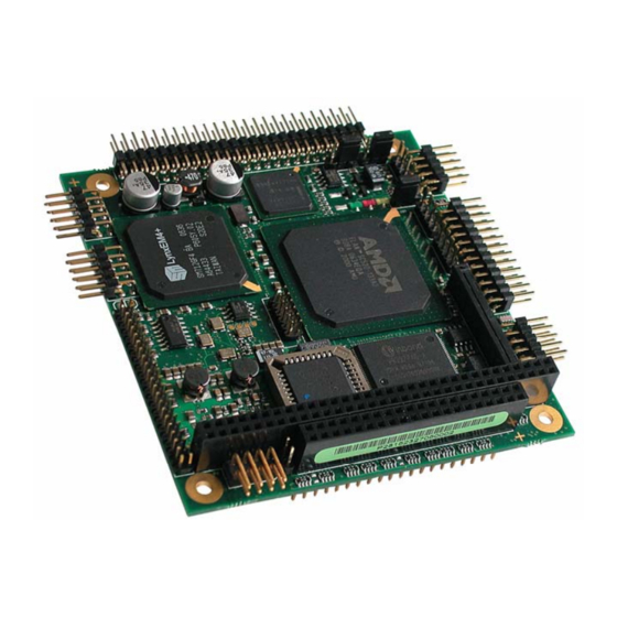
Chapter 2 Introduction Introduction PC/104-520 The PC/104-520 SBC supports the AMD Elan SC520 Embedded System Platform. It's a versatile, low-cost, low-power module that conforms to the industry standard 90mm x 96mm PC/104 form factor. The PC/104-520 features the following: Industry-standard Am5 x 86® CPU with FPU ®... -
Page 8: Pc/104 An Embedded Pc Standard
PC/104 modules are self-stacking. The modules are used like ultra-compact bus boards but do not need backplanes or card cages. Component line applications ® In this configuration, the modules function as highly integrated components, plugged into custom carrier boards that contain application specific interfaces and logic. Kontron User's Guide PC/104-520... -
Page 9: Getting Started
Chapter 3 Getting Started Getting Started The easiest way to get the PC/104-520 board running is to use a starter kit from Kontron Embedded Modules GmbH. Take the following steps: ‚ Connect the power supply to the starter kit baseboard (part of the starter kit). -
Page 10: Specifications
LCD backend controller and 135 MHz RAMDAC • Cathode ray tube (CRT) and LCD flatpanel interface (up to 1024x768 resolution) Insyde BIOS, 256kB Flash BIOS ® Flash BIOS support for CMOS Setup Retention without Battery ® Kontron User's Guide PC/104-520... - Page 11 PS/2 Keyboard Controller ® PS/2 Mouse Controller ® Watchdog timer (WDT) ® Real-time Clock (requires external battery) ® External ISA Bus ® • Full 8/16 bit Memory and I/O access • All ISA IRQ and DMA signals Kontron User's Guide PC/104-520...
-
Page 12: Block Diagram
Floppy Interface GP Bus Parallel General Purpose Bus Port Memory PS/2 Serial PCI Bus SDRAM Interface Interface Ports Keyboard COM A Mouse COM B Graphic Controller LynxEM+ BIOS IDE Interface Network Controller i82551ER PC/104 Connector Transformer Kontron User's Guide PC/104-520... -
Page 13: Mechanical Specifications
One 2x32 pin stackthrough and one 2x20 pin stackthrough connector ® 4.2.2 Module Dimensions 96 x 90mm (3.77” x 3.55”) ® 4.2.3 Height on Top Maximum 11.1mm ® 4.2.4 Height on Bottom Maximum 10.67mm including PC/104 connector ® Kontron User's Guide PC/104-520... -
Page 14: Electrical Specifications
équivalent recommandé par le producteur. L'évacuation des batteries usagées conformément à des indications du fabricant. Danish: ADVARSEL ! Lithiumbatteri – Eksplosionsfare ved fejlagtig Håndtering. Udskifting må kun ske med batteri af samme fabrikant og type. Lever det brugte batteri tilbage til leverand∅ren. Kontron User's Guide PC/104-520... - Page 15 If the battery of this product however is accessible by the end user, it is in the responsibility of the customer to give the corresponding safety instructions in the required language(s). Kontron User's Guide PC/104-520...
-
Page 16: Environmental Specifications
Battery life depends on both temperature and operating conditions. When the Kontron unit has external power; the only battery drain is from leakage paths. -
Page 17: Cpu, Chipset And Super I/O
Integrated watchdog function ® Super I/O The external Super I/O WINBOND W83977F offers the following features: Integrated keyboard controller with PS/2 mouse support ® Two serial ports and one multi-mode parallel port ® Floppy disk controller ® Kontron User's Guide PC/104-520... -
Page 18: Isa Bus Expansion
Chapter 6 ISA Bus Expansion ISA Bus Expansion The design of the PC/104-520 follows the standard PC/104 form factor and offers ISA bus signals for the use of standard PC/104 adapter cards. PC/104 Bus (ISA part) The PC/104 bus consists of two connectors that use 104 pins in total. -
Page 19: Graphics Interface
3.3V-circuitry of the PC/104-520 and the +3.3V logic voltage of low-voltage panels are share the same voltage regulators. To find the location of the LCD Panel interface connector on the PC/104-520 board, please see the Appendix “Connector Layout”. Note: You need to supply the +12V for the backlight converter additionally when using such a converter type. -
Page 20: Connecting A Lcd Panel
Check Jumper J17 for inverting data clock (J17 1-2 = normal 2-3 = inverted). Hint: J17 1-2 default. … Connect the cable to the LCD Panel connector J3 on the PC/104-520 and connect the other end to your display. †... -
Page 21: Extended Vesa Vga Modes
117h Graphics 1024x768 7.4.3 Panel Configuration J16 defines two panel power supplies: +5V and +3.3V. Panel Vcc = +5V Panel Vcc = +3.3V J17 makes it possible to invert the clock signal. Normal Clock Inverted Clock Kontron User's Guide PC/104-520... - Page 22 The following table shows the panel signal assignment. Mono Color STN Color TFT Color TFT Name 18/24 Bit 2x12 Bit FP10 FP11 FP12 FP13 FP14 FP15 FP16 FP17 FP18 FP19 FP20 FP21 FP22 FP23 LP/HSYNC HSYNC HSYNC FLM/VSYNC VSYNC VSYNC 1, 7 Kontron User's Guide PC/104-520...
-
Page 23: Serial-Port Interfaces
- the wires have the right diameter to withstand the maximum available current. - to enclosure of the peripheral device fulfills the fire-protecting conditions of IEC/EN 60950. To find the location of the serial ports on the PC/104-520 board, please see the Appendix “Connector Lay- out”. -
Page 24: Parallel-Port Interface
- the wires have the right diameter to withstand the maximum available current. - to enclosure of the peripheral device fulfills the fire-protecting conditions of IEC/EN 60950. To find the location of the parallel port on the PC/104-520 board, please see the Appendix “Connector Lay- out”. -
Page 25: Keyboard Interface
- to enclosure of the peripheral device fulfills the fire-protecting conditions of IEC/EN 60950. Pin 9 and pin 3 (power connector) are not decoupled. Do not connect two batteries. To find the location of the keyboard and feature connector on the PC/104-520 board, please see the Appendix “Connector Layout”. -
Page 26: Signal Descriptions
A battery is not needed to hold CMOS setup data. Your configurations for hard disks, ® floppy drives, and other peripherals are saved in an onboard EEPROM. However, you need a battery to save the CMOS date and time when power supply is turned off Kontron User's Guide PC/104-520... -
Page 27: Example Connection At-Keyboard And Other Functions
Chapter 10 Keyboard Interface 10.2.1 Example Connection AT-keyboard and Other Functions 6 PIN MINI-DIN (PS/2 STYLE) (KBCLK) (GND) (+5V Vcc) (KBDAT) 5 PIN DIN 180° (DIN41524) (Speaker) (KBCLK) (GND) (KBDAT) (+5V Vcc) (PWRGOOD) (/RESIN) (/KBLOCK) (BATT) Kontron User's Guide PC/104-520... -
Page 28: Ps/2-Mouse Interface
- the wires have the right diameter to withstand the maximum available current. - to enclosure of the peripheral device fulfills the fire-protecting conditions of IEC/EN 60950. To find the location of the PS/2 mouse connector on the PC/104-520 board, please see the Appendix “Connector Layout”. -
Page 29: Ide Interface
96021-0000-00-0) or a 3.5” form factor (KAB-IDE-25, Part Number 96020-0000-00-0). You can plug a Kontron chipDISK, which is an IDE hard disk that uses Flash technology, into the IDE inter- face and mechanically mount it by using a mini-spacer on the chipDISK hole. You also can use a chip-DISK adapter (chipDISK-ADA1, Part Number 96004-0000-00-0) or compact Flash adapter (CFC-ADA1, Part Num- ber 96004-0000-00-2) for more disk support. - Page 30 - to enclosure of the peripheral device fulfills the fire-protecting conditions of IEC/EN 60950. Ω Pin 28 is connected with 470 to Ground for Cable Select IDE devices. To find the location of IDE interface on the PC/104-520 board, please see the Appendix “Connector Layout”. Kontron User's Guide PC/104-520...
-
Page 31: Ethernet Controller
RXD+, RXD- differential input pair receives 10 and 100 Mb/s Manchester-encoded data from 100/ 10BASE-T receive lines. To find the location of the Ethernet interface on the PC/104-520 board, please see the Appendix “Connector Layout”. Kontron User's Guide PC/104-520... -
Page 32: Floppy-Drive Interface
14. Floppy-Drive Interface The floppy-drive interface of the PC/104-520 uses a 2.88 MB super I/O floppy-disk controller and can sup- port one floppy disk drive with densities that range from 360 kB to 2.88 MB. The controller is 100% IBM compatible. -
Page 33: Power Connector
In some applications, the PC/104-520 is intended for use as a stand-alone module without a backplane. You need to have a power connector available on the board for direct power supply. The PC/104-520 is a +5V only board. Peripherals can obtain additional voltage from the power connector next to the PC/104 bus. The additional voltages (+12V, -5V and -12V) are not generated onboard the PC/104-520. -
Page 34: External Battery
Note: The PC/104-520 is not a replacement for a backplane. Use all power pins on the power connector and on the PC/104 connectors for power supply to the PC/104-520, and also use all additional power connectors on addi- tional I/O cards if your system exceeds the above limitations. -
Page 35: Watchdog Timer
Watchdog Timer 16. Watchdog Timer The watchdog timer (WDT) is integrated in the Winbond W83977F controller of the PC/104-520 and can issue a reset to the system. The watchdog timer circuit has to be triggered within a specified time by the application software. -
Page 36: Dma Configuration
DACK3 DACK5 GPACK1 DACK6 DACK7 Note: In addition to JP1 there is the possibility to connect DACK3 to GPACK1 instead of DACK5-7. Use R90 for this purpose. Please select the configuration also in the BIOS setup. Kontron User's Guide PC/104-520... -
Page 37: Dma Request
DREQ3 DREQ5 GPREQ1 DREQ6 DREQ7 Note: In addition to JP2 there is the possibility to connect DREQ3 to GPREQ1 instead of DREQ5-7. Use R91 for this purpose. Please select the configuration also in the BIOS setup. Kontron User's Guide PC/104-520... -
Page 38: Onboard Device Configuration
BIOS Extensions Startup / Dark Boot (Miscellaneous) Startup / Fast Boot Startup / Show '<CTRL-ALT-S> ..' Startup / Wait for F1 on Error Startup / Remote Control Startup / Setup Password Components / Enable Standard PIT Kontron User's Guide PC/104-520... -
Page 39: Setup Guide
<Space> key to accept the selection. Enabled / Disabled Functionality Enabled is represented by a ' ' and Disabled by a ' Note: In the Option column, bold shows default settings. Kontron User's Guide PC/104-520... -
Page 40: Startup Menu
02: 640x480 STN 16Bit 05: 640x480 TFT 18Bit 06: 1024x768 TFT 2x12Bit 07: 800x600 TFT 18Bit 16.2V, 16.4V, 16.6V, 16.9V Sets the contrast voltage for STN LCD pa- 8Adjust BIAS Voltage nels 17.2V, ..., 29.3V, 30.1V, 31.1V Kontron User's Guide PC/104-520... -
Page 41: Memory Menu
Number of heads Sectors/Track Number of sectors per track Landing Zone Defines the head park position Write Precomp Write precompensation cylinder number LBA Range Number of logical blocks Size (MB) Displays the calculated size of the drive Kontron User's Guide PC/104-520... -
Page 42: Components Menu
15 cps, 20 cps, 30 cps Key Delay 1/4 sec, 1/2 sec Sets the delay time after the key is held down before it begins to repeat the keystroke 3/4 sec, 1 sec Kontron User's Guide PC/104-520... -
Page 43: Pci/Isa Menu
19.8.2 Configure DMA Channels Submenu Feature Option Description DMA A Channel DMA0 (Memory) Selects 8 Bit DMA channel for GPACK0/GPREQ0 DMA1 DMA2 (FDD) DMA3 (HDD) DMA B Channel DMA5 Selects 16 Bit DMA channel for GPACK1/GPREQ1 DMA6 DMA7 Kontron User's Guide PC/104-520... -
Page 44: Exit Menu
Exits Setup without storing in CMOS any new selec- tions you may have made. The selections previously Cancel in effect remain in effect Factory Settings Sets default values for all Setup menus Cancel Version Info Shows version information Kontron User's Guide PC/104-520... -
Page 45: Kontron Bios Extensions
During boot-up, the system BIOS scans the ports for an available connection. If detected, it starts the remote session. The connection between the target system (PC/104-520) and the host (Desktop PC) occurs over the serial or parallel port via a special cable: ‚... - Page 46 Example: SC520Rmt /P:COM1 -F If the disable-option are used the redirection to the host hardware is disabled and the target hardware is used instead. To exit the program on the host press both SHIFT keys. Kontron User's Guide PC/104-520...
-
Page 47: Updating The Bios
19.11.1 Flashing a BIOS Use the following procedure to update the BIOS. ‚ Download the update program from the KONTRON Embedded Modules Website or contact your local technical support for it. ƒ Use SC520Upd with following arguments: SC520Upd [options] <filename>... -
Page 48: Appendix A: System Resourcen
Appendix A: System Resourcen A.1 Interrupt Request Lines Please note that Kontron PC/104 devices were designed after the draft of P996 Specification for ISA systems. Because of this, shareable interrupts are not supported. Some PC/104 add-on board manu- facturers do not follow the P996 Specification and allow shareable interrupts. If you want to use such PC/104 boards with Kontron devices, contact the manufacturer of the add-on board and ask about switching to non-interrupt sharing. -
Page 49: Direct Memory Access (Dma) Channels
System Resourcen A.2 Direct Memory Access (DMA) Channels DMA # Used for Available Comment Floppy Note (1) Cascade Note: If the „used for“ device is disabled in setup, the corresponding DMA channel is available for other devices. Kontron User's Guide PC/104-520... -
Page 50: I/O Address Map
System Resourcen A.3 I/O Address Map The I/O-port addresses of the processor module PC/104-520 are functionally identical to a standard PC/AT. All addresses not mentioned in this table should be available. We recommend that you do not use I/O addresses below 0110h with additional hardware for compatibility reasons, even if available. -
Page 51: Memory Map
OS control memory and I/O resources. Please see the PCI 2.1/2.2 specification for details. PCI Device (IDSEL) PCI IRQ REQ / GNT Comment Onboard Host Bridge None Integrated in SC520 Onboard Graphic Controller INTA REQ0/GNT0 External LynxEM+ (SM712) Onboard Network Controller INTB REQ1/GNT1 External i82551ER Kontron User's Guide PC/104-520... -
Page 52: Appendix B: Connector Layout
Appendix B Connector Layout Appendix B: Connector Layout Pin 1 The Board as depicted is a model only, showing the positions of the connectors. For pincount and pinning please see the following tables. Kontron User's Guide PC/104-520... -
Page 53: Connector Functions & Interface Cables
(PN 96001-0000-00-0) adaptation KAB-FLOPPY/MOPS-1 (PN 96019-0000-00-0) Ethernet 2.54mm 4 pos. KAB-PC104520-ETN for RJ45 Interface (W+P Products 943-12-004-00 (PN 96231-0200-00-0) adaptation Connector or compatible) Infrared 2.54mm 4 pos. for special Connector (W+P Products 943-12-004-00 adaptation or compatible) Kontron User's Guide PC/104-520... -
Page 54: Pinout Table
SA19 /SMEMR /DACK6 SA18 /IOW SD10 DRQ6 SA17 /IOR SD11 /DACK7 SA16 /DACK3 SD12 DRQ7 SA15 DRQ3 SD13 SA14 /DACK1 SD14 SA13 DRQ1 SD15 SA12 /REFRESH SA11 SYSCLK SA10 IRQ7 IRQ6 IRQ5 IRQ4 IRQ3 /DACK2 BALE Kontron User's Guide PC/104-520... - Page 55 /ACK KEY (NC) PANEL VCC /TRK0 PANEL VCC BUSY /WRTPRT /IOW CONTRAST+ /RDATA /IOR CONTRAST- SLCT /HDSEL IOCHRDY CSEL /ACK SIRQ /IOCS16 FP14 FP15 /CS1 /CS3 /DASP FP10 FP18 FP11 FP17 FP12 FP16 FP13 FP23 FP22 Kontron User's Guide PC/104-520...
- Page 56 To protect the external power lines of peripheral devices, make sure that - the wires have the right diameter to withstand the maximum available current. - the enclosure of the peripheral device fulfils the fire protecting conditions of IEC/EN 60950. No delay to SA lines. Kontron User's Guide PC/104-520...
-
Page 57: Appendix C: Literature Hints
ISA System Architecture, Third Edition, Tom Shanley and Don Anderson, Addison-Wesley ® Publishing Company, 1995, ISBN 0-201-40996-8 Personal Computer Bus Standard P996, Draft D2.00, Jan. 18, 1990, IEEE Inc. ® Technical Reference Guide, Extended Industry Standard Architecture Expansion Bus, ® Compaq 1989 Kontron User's Guide PC/104-520... -
Page 58: Pci/Pc-104
USB Specification. USB Implementers Forum, Inc. is a non-profit corporation founded ® by the group of companies that developed the Universal Serial Bus specification. The USB-IF was formed to provide a support organization and forum for the advancement Kontron User's Guide PC/104-520... -
Page 59: Programming
The Programmer’s PC Sourcebook, Second Edition, Thom Hogan, Microsoft Press, 1991, ® ISBN 1-55615-321-X Undocumented PC, A Programmer’s Guide to I/O, CPUs, and Fixed Memory Areas, Frank ® van Gilluwe, Second Edition, Addison-Wesley, 1997, ISBN 0-201-47950-8 Kontron User's Guide PC/104-520... -
Page 60: Appendix D: Revision History
Appendix D Revision History APPENDIX D: REVISION HISTORY Revision Date Edited by Changes 07/24/2007 M. Hüttmann First revision 11/30/2007 M. Hüttmann Change min. operating temperature 12/05/2007 M. Hüttmann Added battery safety instructions Kontron User's Guide PC/104-520...
Need help?
Do you have a question about the PC/104-520 and is the answer not in the manual?
Questions and answers