
Related Manuals for Kontron 3.5"-SBC-VR1000


Summary of Contents for Kontron 3.5"-SBC-VR1000
- Page 1 USER GUIDE 3.5"-SBC-VR1000 Doc. User Guide, Rev. 1.0 Doc. ID: [To be Determined] www.kontron.com...
- Page 2 3.5"-SBC-VR1000 - User Guide, Rev. 1.0 This page has been intentionally left blank www.kontron.com // 2...
- Page 3 In cases of doubt, please contact Kontron. This user guide is protected by copyright. All rights are reserved by Kontron. No part of this document may be reproduced, transmitted, transcribed, stored in a retrieval system, or translated into any language or computer language, in any form or by any means (electronic, mechanical, photocopying, recording, or otherwise), without the express written permission of Kontron.
- Page 4 ENVIRONMENTAL DAMAGE (COLLECTIVELY, "HIGH RISK APPLICATIONS"). You understand and agree that your use of Kontron devices as a component in High Risk Applications is entirely at your risk. To minimize the risks associated with your products and applications, you should provide adequate design and operating safeguards.
- Page 5 If you have any difficulties using this user guide, discover an error, or just want to provide some feedback, contact Kontron support. Detail any errors you find. We will correct the errors or problems as soon as possible and post the revised user guide on our website.
-
Page 6: Symbols
Eye protection per manufacturer notice shall review before servicing. This symbol indicates general information about the product and the user guide. This symbol also indicates detail information about the specific product configuration. This symbol precedes helpful hints and tips for daily use. www.kontron.com // 6... -
Page 7: For Your Safety
Therefore, in the interest of your own safety and of the correct operation of your new Kontron product, you are requested to conform with the following guidelines. -
Page 8: Lithium Battery Precautions
General Instructions on Usage In order to maintain Kontron’s product warranty, this product must not be altered or modified in any way. Changes or modifications to the product, that are not explicitly approved by Kontron and described in this user guide or received from Kontron Support as a special handling instruction, will void your warranty. -
Page 9: Table Of Contents
7.3. SATA (Serial ATA) Port 0 & 1 Connector (SATA1 & SATA2) ......................32 7.4. HDD / SSD Power Output Wafer (CN15) ............................33 7.5. USB Connectors (Internal) (CN9 & CN10) ............................34 7.6. Audio AMP Output Wafer (CN13 & CN23) ............................34 www.kontron.com // 9... -
Page 10: List Of Tables
8.2.5. Security Setup Menu ................................... 83 8.2.6. Save & Exit Setup Menu ..................................85 Appendix A: List of Acronyms ..................................86 About Kontron ........................................87 List of Tables Table 1: Component Main Data ..................................17 Table 2: Environmental Conditions ................................18 Table 3: Standards and Certifications ............................... -
Page 11: List Of Figures
Figure 20: Front Panel 1 Pin Header FP1 ..............................36 Figure 21: Front Panel 2 Pin Header FP2 ..............................36 Figure 22: Serial COM CN12, CN17, CN21, CN22 ............................38 Figure 23: LVDS Connector LVDS1 ................................40 Figure 24: Backlight Power Output Wafer CN8 ............................. 42 www.kontron.com // 11... - Page 12 Figure 61: BIOS Power Setup Menu - WatchDog Timer Configuration ................... 81 Figure 62: BIOS Boot Setup Menu ................................82 Figure 63: BIOS Security Setup Menu ................................ 83 Figure 64: BIOS Save & Exit Setup Menu ..............................85 www.kontron.com // 12...
-
Page 13: 1/ Introduction
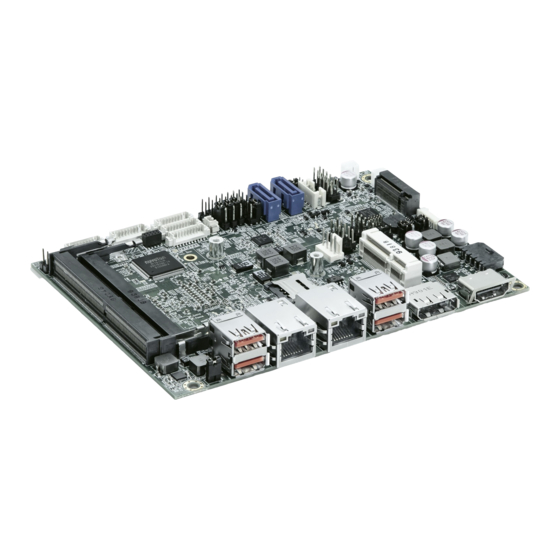
3.5"-SBC-VR1000 - User Guide, Rev. 1.0 1/ Introduction This user guide describe the 3.5"-SBC-VR1000 board made by Kontron. This board will also be denoted 3.5"-SBC- VR1000 within this user guide. Use of this user guide implies a basic knowledge of PC-AT hardware and software. This user guide focuses on describing the 3.5"-SBC-VR1000 board's special features and is not intended to be a standard PC-AT textbook. -
Page 14: 2/ Installation Procedures
Handle the board only by the edges To get the board running follow these steps. If the board shipped from KONTRON already has components like RAM and CPU cooler mounted, then skip the relevant steps below. 1. Turn off the PSU (Power Supply Unit) Turn off PSU (Power Supply Unit) completely (no mains power connected to the PSU) or leave the Power Connectors unconnected while configuring the board. -
Page 15: Chassis Safety Standards
Använd samma batterityp eller en ekvivalent typ som rekommenderas av apparattillverkaren Kassera använt batteri enligt fabrikantens instruktion VAROITUS! Paristo voi räjähtää, jos se on virheellisesti asennettu. Vaihda paristo ainoastaan lalteval- mistajan suosittelemaan tyyppiln Hävitä käytetty paristo valmistajan ohjeiden mukaisesti www.kontron.com // 15... -
Page 16: 3/ System Specifications
3.5"-SBC-VR1000 - User Guide, Rev. 1.0 3/ System Specifications 3.1. System Block Diagram Figure 1: System Block Diagram 3.5"-SBC-VR1000 www.kontron.com // 16... -
Page 17: Component Main Data
AMI uEFI BIOS w/ 64 Mb SPI Flash Watchdog Programmable WDT to generate system reset event H/W Monitor Voltages Temperatures Real Time Clock Processor integrated RTC TPM 2.0 support (Infineon SLB 9665) System Control & Monitoring www.kontron.com // 17... -
Page 18: Environmental Conditions
-20 °C ~ 80 °C / -4 °F ~ 176 °F (Standard) Humidity 0 % ~ 95 % 3.4. Standards and Certifications The 3.5"-SBC-VR1000 meets the following standards and certification tests. Table 3: Standards and Certifications CE Class A FCC Class A www.kontron.com // 18... -
Page 19: Processor Support
The 3.5"-SBC-VR1000 is designed to support AMD Ryzen™ V1000 / R1000 Series Processors. The BGA CPU is remounted from factory. Kontron has defined the board versions as listed in the following table, so far all based on Embedded CPUs. Other versions are expected at a later date. -
Page 20: On-Board Graphics Subsystem
Memory modules have in general a much lower longevity than embedded motherboards, and therefore EOL of modules can be expected several times during lifetime of the motherboard. As a minimum it is recommend using Kontron memory modules for prototype system(s) in order to prove stability of the system and as for reference. -
Page 21: 4/ Connector Locations
EEPROM WP Selection 7.17.1 Backlight Enable Selection 7.17.2 Panel & Backlight Power Selection 7.17.3 AT / ATX Power Mode Selection 7.17.4 USB Power Selection 7.17.5 Clear CMOS Selection 7.17.6 Backlight Adjustment Selection 7.17.7 JP10 LVDS EDID Selection 7.17.8 www.kontron.com // 21... -
Page 22: Table 9: Top Side Internal Connector Pin Assignment
DC 12 V Fan Wafer Front Panel 1 Pin Header Front Panel 2 Pin Header M2M2 NGFF M.2 Key M Socket 7.14 MPCIE1 Mini-PCI Express V1.2 Socket 7.13 SATA1 Serial ATA Port 0 Connector SATA2 Serial ATA Port 1 Connector www.kontron.com // 22... -
Page 23: Rear Side
3.5"-SBC-VR1000 - User Guide, Rev. 1.0 4.2. Rear Side Figure 3: Rear Side Table 10: Rear Side Internal Connector Pin Assignment Item Designation Description See Chapter LVDS1 18/24-bit, 2-channel LVDS Panel Connector 7.10 www.kontron.com // 23... -
Page 24: Connector Panel Side
DP Connector USB 3.1 Port 1, 2 Type A Connector (V1000 Model) USB 2.0 Port 1, 2 Type A Connector (R1000 Model) USB 3.1 Port 3, 4 Type A Connector GbE LAN1 RJ45 Connector GbE LAN2 RJ45 Connector www.kontron.com // 24... -
Page 25: 5/ Connector Definitions
Type and number of item described See Chapter Number of the chapter within this user guide containing a detailed description The abbreviation TBD is used for specifications that are not available yet or which are not sufficiently specified by the component vendors. www.kontron.com // 25... -
Page 26: 6/ I/O-Area Connectors
HDMI Clock differential pair (+) Ground TMDS Clock– HDMI Clock differential pair (-) Reserved Reserved DDC_CLK DDC based control signal (clock) DDC_DATA DDC based control signal (data) Ground +5 V Power +5 V power supply Hot Plug Detect www.kontron.com // 26... -
Page 27: Dp Connector (Cn2)
DisplayPort Lane 3 transmitter differential pair (+) Ground TX3- DisplayPort Lane 3 transmitter differential pair (-) Ground Ground AUX+ DisplayPort Auxiliary channel differential pair (+) Ground AUX- DisplayPort Auxiliary channel differential pair (-) DisplayPort hot plug detect Ground Power for connector www.kontron.com // 27... -
Page 28: Ethernet Connectors (Cn5 & Cn6)
BI_DD+/- pair. TX4+ / TX4- In MDI mode, this is the fourth pair in 1000Base-T, i.e. the BI_DD+/- pair.In MDI crossover mode, this pair acts as the BI_DC+/- pair. 'MDI' – media dependent Interface www.kontron.com // 28... -
Page 29: Usb Connectors (I/O Area)
Table 16: Pin Assignment USB 2.0 Connectors CN3 - Top & Bottom (V1000 model) Signal Description Note +USB_VCC* +5 V power supply for USB device USB_D- USB 2.0 differential pair (-) USB_D+ USB 2.0 differential pair (+) Ground * The power source of +USB_VCC can be selected by JP6. www.kontron.com // 29... -
Page 30: Figure 10: Usb 2.0 High Speed Cable
For USB 3.1 cabling it is required to use only HiSpeed USB cable, specified in USB3.1 standard: Figure 11: USB 3.1 High Speed Cable Filler, optional UTP Signal Pair SDP Signal Pair Braid Jacket Power Ground SDP Signal Pair www.kontron.com // 30... -
Page 31: 7/ Internal Connectors
Figure 13: CR2032 Battery Power Input Wafer BAT1 Table 18: Pin Assignment BAT1 Signal Description Note Battery+ Real-time clock backup battery input Battery- Ground reference www.kontron.com // 31... -
Page 32: Fan Wafer (Fan1)
Figure 15: SATA Port 0, 1 Connector SATA1, SATA2 Table 20: Pin Assignment SATA1, SATA2 Signal Description Note Ground Host transmitter differential signal pair (+) Host transmitter differential signal pair (-) Ground Host receiver differential signal pair (-) Host receiver differential signal pair (+) Ground www.kontron.com // 32... -
Page 33: Hdd / Ssd Power Output Wafer (Cn15)
The 1x4-pin 2.0 mm pitch HDD / SSD power output wafer provides power to the SATA hard disk. Figure 16: HDD / SSD Power Output Wafer CN15 Table 21: Pin Assignment CN15 Signal Description Note +12V +12 V power supply for HDD / SSD Ground Ground +5 V power supply for HDD / SSD www.kontron.com // 33... -
Page 34: Usb Connectors (Internal) (Cn9 & Cn10)
(Line-out) signals of the audio pin header CN14. Figure 18: Audio AMP Output Wafer CN13 (Right Channel), CN23 (Left Channel) Table 23: Pin Assignment CN13, CN23 Signal Description Note Speaker+ Speaker output (+) Speaker- Speaker output (-) www.kontron.com // 34... -
Page 35: Audio Input / Output Pin Header (Cn14)
Ground Line-In_L Audio input left channel signal Line-In_R Audio input right channel signal Line-In_JD# Audio input jack detection Ground Line-Out_L Audio output left channel signal Line-Out_R Audio output right channel signal Line-Out_JD# Audio output jack detection Ground www.kontron.com // 35... -
Page 36: Front Panel Pin Header (Fp1 & Fp2)
System power button (+). Pressing the power button turns the system on or puts the system in sleep or soft-off mode depending on the operating system settings. Pressing the power switch for more than four seconds while the system turns from ON to OFF. No connection www.kontron.com // 36... - Page 37 It also can be used to signal some other external power management event. SMBus Data System management bus bidirectional data line Ground SMBus Clock System management bus bidirectional clock line www.kontron.com // 37...
-
Page 38: Serial Com1, Com2, Com3 & Com4 Ports (Cn12, Cn17, Cn21 & Cn22)
Figure 22: Serial COM CN12, CN17, CN21, CN22 Table 27: Pin Assignment CN12, CN17 RS232 Signal RS422 Signal Half Duplex RS485 Full Duplex RS485 Note Signal Signal DATA- DATA+ Table 28: Pin Assignment CN21, CN22 RS232 Signal Note Table 29: Signal Description www.kontron.com // 38... - Page 39 Ring Indicator, indicates that the modem has received a ringing signal from the telephone line. TX+/- Transmitted Data differential pair sends data to the communications link. RX+/- Received Data differential pair receives data from the communications link. Power Supply GND signal www.kontron.com // 39...
-
Page 40: Lvds Panel Connector (Lvds1)
LVDS Channel B Data 1 differential pair (-) Ground LVDS_B2- LVDS Channel B Data 2 differential pair (-) LVDS_B2+ LVDS Channel B Data 2 differential pair (+) LVDS_BCLK- LVDS Channel B clock differential pair (-) LVDS_BCLK+ LVDS Channel B clock differential pair (+) www.kontron.com // 40... - Page 41 +3.3 V / +5 V panel power supply +3.3V / +5V * +3.3 V / +5 V panel power supply +3.3V / +5V * +3.3 V / +5 V panel power supply * Panel Power can be selected by JP3. www.kontron.com // 41...
-
Page 42: Backlight Power Output Wafer (Cn8)
+5V / +12V** +5 V / +12 V backlight power supply Ground BL_EN*** Backlight Enable signal * BL_ADJ can be configured in BIOS setup. ** Backlight Power can be selected by JP3. *** BL_EN can be selected by JP2. www.kontron.com // 42... -
Page 43: Digital Input / Output Header (Cn20)
Digital input / output channel 2 DIO_3 Digital input / output channel 3 DIO_4 Digital input / output channel 4 DIO_5 Digital input / output channel 5 DIO_6 Digital input / output channel 6 DIO_7 Digital input / output channel 7 Ground www.kontron.com // 43... -
Page 44: Mpcie Socket (Mpcie1)
Reset signal for User Identity Modules (UIM) Ground UIM_VPP* Variable supply voltage for User Identity Module (UIM) Reserved Ground Reserved W_Disable# Wireless disable signal Ground PERST# PCI Express reset PERn0 PCIe Lane 0 receiver differential pair (-) +3.3VSB +3.3 V standby power supply www.kontron.com // 44... - Page 45 LED status indicator signal for WLAN Reserved LED_WPAN# LED status indicator signal for WPAN Reserved +1.5V +1.5 V power supply Reserved Ground Reserved +3.3VSB +3.3 V standby power supply * These pins are connected to SIM1 Micro SIM card holder directly. www.kontron.com // 45...
-
Page 46: Key M Socket (M2M2)
PCIe Lane 2 receiver pair (-) +3.3V 3.3 V power supply M2M_RXP2 PCIe Lane 2 receiver pair (+) No connection Ground No connection M2M_TXN2 PCIe Lane 2 transmitter pair (-) No connection M2M_TXP2 PCIe Lane 2 transmitter pair (+) No connection www.kontron.com // 46... - Page 47 PCIe Lane 0 transmitter pair (+) PERST# PCIe reset Ground CLKREQ# Reference clock request signal REFCLKn PCIe reference clock pair (-) PEWAKE# PCIe wake REFCLKp PCIe reference clock pair (+) No connection Ground No connection No connection No connection www.kontron.com // 47...
- Page 48 3.5"-SBC-VR1000 - User Guide, Rev. 1.0 Signal Description Note PEDET PCIe detect +3.3V 3.3 V power supply Ground +3.3V 3.3 V power supply Ground +3.3V 3.3 V power supply Ground www.kontron.com // 48...
-
Page 49: Micro Sim Card Holder (Sim1)
The Micro SIM card holder SIM1 is intended to accommodate an Micro SIM card and connected to UIM signals on the mPCIe socket. Figure 28: Micro SIM Card Holder SIM1 Table 35: Pin Assignment SIM1 Signal Description Note Power +3.3 V Ground Reset signal Programming voltage input Clock signal Input or Output for serial data www.kontron.com // 49... -
Page 50: Key M / Mpcie Activity Led Pin Header (Cn18 & Cn19)
The header CN18 is intended to connect M.2 Key M activity LED cable. The pin header CN19 is intended to connect mPCIe activity LED cable. Figure 29: M.2 Key M / mPCIe Activity LED Pin Header CN18, CN19 Table 36: Pin Assignment CN18, CN19 Signal Description Note LED+ LED- www.kontron.com // 50... -
Page 51: Switches And Jumpers
The 2.54 mm pitch "EEPROM Write Protect Selection" jumper (JP1) can be used to update EEPROM firmware. Figure 31: EEPROM WP Selection JP1 Table 37: Pin Assignment JP1 Jumper 1 Position Description Pin 1-2 Memory is inhibited Allows normal write “X” = Jumper set (short) and “-” = jumper not set (open) www.kontron.com // 51... -
Page 52: Backlight Enable Selection (Jp2)
Backlight Enable Level = +3.3 V Backlight Enable Level = +5 V Jumper 2 Position Description Pin 2-4 Pin 4-6 Backlight Enable High Active Backlight Enable Low Active “X” = Jumper set (short) and “-” = jumper not set (open) www.kontron.com // 52... -
Page 53: Panel & Backlight Power Selection (Jp3)
Figure 34: AT / ATX Power Mode Selection JP5 Table 40: Pin Assignment JP5 Jumper 1 Position Description Pin 1-2 Pin 2-3 ATX Mode AT Mode “X” = Jumper set (short) and “-” = jumper not set (open) www.kontron.com // 53... -
Page 54: Usb Power Selection (Jp6)
Clear CMOS (board does not boot with the jumper in this position) “X” = Jumper set (short) and “-” = jumper not set (open) Do not leave the jumper in position 2-3, otherwise if the power is disconnected, the battery will fully deplete within a few weeks. www.kontron.com // 54... -
Page 55: Backlight Adjustment Selection (Jp9)
The 2.0 mm pitch "LVDS EDID Selection" jumper (JP10) can be used to update LVDS firmware. Figure 38: LVDS EDID Selection JP10 Table 44: Pin Assignment JP10 Jumper 1 Position Description Pin 1-2 Pin 2-3 Normal LVDS EDID Write “X” = Jumper set (short) and “-” = jumper not set (open) www.kontron.com // 55... -
Page 56: 8/ Bios
8/ BIOS 8.1. Starting the uEFI BIOS The 3.5"-SBC-VR1000 is provided with a Kontron-customized, pre-installed and configured version of AMI Aptio® V uEFI BIOS. AMI BIOS firmware is based on the Unified Extensible Firmware Interface (UEFI) specification and the Intel®... -
Page 57: Starting The Uefi Bios
Read only field. Displays information about total memory ME Information Read only field. Displays information about Intel Management Engine (ME) version Firmware Information Code version and firmware information System Date Set System Date System Time Set System Time www.kontron.com // 57... -
Page 58: Figure 39: Bios Main Menu
Version 2.20.1274. Copyright (C) 2020, American Megatrends, Inc. Feature Option Description System Date [dd/mm/yyyy] Set the Date. Use Tab to switch between Data elements. System Time [hh:mm:ss] Set the Time. Use Tab to switch between Time elements. www.kontron.com // 58... -
Page 59: Figure 40: Bios Main Menu - Amd Firmware Version
MP2 I2C RV2 FW Version 1.2.2.3 F1: General Help F2: Previous Values XHCI FW Version FF.FF.FF.FF F3: Optimized Defaults VBIOS FW Version 113-RAVEN2-117 F4: Save & Exit GOP Driver Version ESC: Exit Version 2.20.1274. Copyright (C) 2020, American Megatrends, Inc. www.kontron.com // 59... -
Page 60: Advanced Setup Menu
USB Configuration Trusted Computing DIO Configuration Super IO Configuration H/W Monitor Tls Auth Configuration Network Stack Configuration Setting items on this screen to incorrect values may cause the system to malfunction. www.kontron.com // 60... -
Page 61: Figure 41: Bios Advanced Menu
Select whether to enable or disable load onboard PXE (Preboot Execution Environment) or uEFI-SNP (Simple Network Protocol). Intel I210-AT. LAN Boot I211-AT [Disabled], [Load PXE] Select whether to enable or disable load onboard PXE (Preboot Execution Environment) or uEFI-SNP (Simple Network Protocol). Intel I211-AT. www.kontron.com // 61... -
Page 62: Figure 42: Bios Advanced Menu - Display Configuration
[By External]: Control by external HW circuit. [By Internal]: Control by LBKL_CTL on the AMD Chipset. LVDS Backlight [Voltage], [PWM] CN8 LVDS Backlight Power Wafer output control Control Mode [Voltage]: Pin 1 output [PWM]: Pin 2 output www.kontron.com // 62... - Page 63 3.5"-SBC-VR1000 - User Guide, Rev. 1.0 Feature Option Description LVDS Backlight [0.0 V], [0.5 V], [1.0 V], Min: 0.0 V Control - Voltage [1.5 V], [2.0 V], [2.5 V], Max: 5.0 V [3.0 V], [3.5 V], [4.0 V], [4.5 V], [5.0 V] www.kontron.com // 63...
-
Page 64: Figure 43: Bios Advanced Menu - Cpu Chipset Configuration
Active Processor [All], [1 CPU Cores], [2 Select number of cores to be used. Cores CPU Cores], [3 CPU WARNING - S3 is NOT SUPPORTED on systems where cores / Cores] threads have been removed / disabled. www.kontron.com // 64... -
Page 65: Figure 44: Bios Advanced Menu - Nvme Configuration
No NVMe Device Found → ←: Select Screen ↑ ↓: Select Item Enter: Select +/-: Change Opt. F1: General Help F2: Previous Values F3: Optimized Defaults F4: Save & Exit ESC: Exit Version 2.20.1274. Copyright (C) 2020, American Megatrends, Inc. www.kontron.com // 65... -
Page 66: Figure 45: Bios Advanced Menu - Sata Configuration
F4: Save & Exit ESC: Exit Version 2.20.1274. Copyright (C) 2020, American Megatrends, Inc. * These items appear only when enabling SATA Controller. Feature Option Description SATA Controller [Enabled], [Disabled] Select whether to enable or disable OnChip SATA Controller. www.kontron.com // 66... -
Page 67: Figure 46: Bios Advanced Menu - Usb Configuration
This is a workaround for OSes without XHCI hand-off support. The XHCI ownership change should be claimed by XHCI driver. USB Mass Storage [Disabled], [Enabled] Select whether to enable or disable USB Mass Storage Driver Driver Support Support. www.kontron.com // 67... -
Page 68: Figure 47: Bios Advanced Menu - Trusted Computing
Version 2.20.1274. Copyright (C) 2020, American Megatrends, Inc. Feature Option Description Security Device [Disabled], [Enabled] Select whether to enable or disable BIOS support for security Support device. O.S. will not show Security Device. TCG EFI protocol and INT1A interface will not be available. www.kontron.com // 68... -
Page 69: Figure 48: Bios Advanced Menu - Dio Configuration
* These items appear only when enabling User Configuration. Feature Option Description User Configuration [Enabled], [Disabled] Select whether to allow user to set the DO pin output value DIO_0..7 [Output Low], [Output Setting the DO pin output value High], [Input] www.kontron.com // 69... -
Page 70: Figure 49: Bios Advanced Menu - Super Io Configuration
[No Protection], [Keep Set Super IO Serial Port into Device D3 or not. Protection Device On] [No Protection]: UART device have be entry D3 for OS control. [Keep Device On]: Protection UART device not entry D3 state. www.kontron.com // 70... -
Page 71: Figure 50: Bios Advanced Menu - Super Io Configuration - Serial Port 1 Configuration
Select an appropriate RS485 Duplex Mode. Duplex] RS485 Auto Flow [Disabled], [Enabled] Select whether to enable or disable RS485 Auto Flow Control. Control RS485/422 Receiver [Disabled], [Enabled] Select whether to enable or disable RS485/422 Receiver Termination Termination. www.kontron.com // 71... -
Page 72: Figure 51: Bios Advanced Menu - Super Io Configuration - Serial Port 2 Configuration
Select an appropriate RS485 Duplex Mode. Duplex] RS485 Auto Flow [Disabled], [Enabled] Select whether to enable or disable RS485 Auto Flow Control. Control RS485/422 Receiver [Disabled], [Enabled] Select whether to enable or disable RS485/422 Receiver Termination Termination. www.kontron.com // 72... -
Page 73: Figure 52: Bios Advanced Menu - Super Io Configuration - Serial Port 3 Configuration
IRQ=3, 4, 5, 6, 7, 9, 10, 11, 12;], [IO=2E8h; IRQ=3, 4, 5, 6, 7, 9, 10, 11, 12;], [IO=2F0h; IRQ=3, 4, 5, 6, 7, 9, 10, 11, 12;], [IO=2E0h; IRQ=3, 4, 5, 6, 7, 9, 10, 11, 12;] www.kontron.com // 73... -
Page 74: Figure 53: Bios Advanced Menu - Super Io Configuration - Serial Port 4 Configuration
IRQ=3, 4, 5, 6, 7, 9, 10, 11, 12;], [IO=2E8h; IRQ=3, 4, 5, 6, 7, 9, 10, 11, 12;], [IO=2F0h; IRQ=3, 4, 5, 6, 7, 9, 10, 11, 12;], [IO=2E0h; IRQ=3, 4, 5, 6, 7, 9, 10, 11, 12;] www.kontron.com // 74... -
Page 75: Figure 54: Bios Advanced Menu - H/W Monitor
F1: General Help : +5.066 V F2: Previous Values +VMEM : +1.299 V F3: Optimized Defaults +3.3V : +3.360 V F4: Save & Exit +VRTC : +3.280 V ESC: Exit Version 2.20.1274. Copyright (C) 2020, American Megatrends, Inc. www.kontron.com // 75... -
Page 76: Figure 55: Bios Advanced Menu - H/W Monitor - Smart Fan Configuration
* This item appears only when selecting Manual for CPU FAN Setting. ** These items appear only when selecting Smart for CPU FAN Setting. Feature Option Description CPU FAN Setting [Manual], [Smart] Switch the CPU FAN control mode. www.kontron.com // 76... -
Page 77: Figure 56: Bios Advanced Menu - Tls Auth Configuration
> Delete Cert → ←: Select Screen ↑ ↓: Select Item Enter: Select +/-: Change Opt. F1: General Help F2: Previous Values F3: Optimized Defaults F4: Save & Exit ESC: Exit Version 2.20.1274. Copyright (C) 2020, American Megatrends, Inc. www.kontron.com // 77... -
Page 78: Figure 58: Bios Advanced Menu - Tls Auth Configuration - Server Ca Configuration - Enroll Cert
+/-: Change Opt. F1: General Help F2: Previous Values F3: Optimized Defaults F4: Save & Exit ESC: Exit Version 2.20.1274. Copyright (C) 2020, American Megatrends, Inc. Feature Option Description Cert GUID [11111111-2222-3333- Input digit character in 11111111-2222-3333-4444-1234567890ab 4444-1234567890ab] format. www.kontron.com // 78... -
Page 79: Figure 59: Bios Advanced Menu - Network Stack Configuration
Ipv6 HTTP Support [Disabled], [Enabled] Select whether to enable or disable Ipv6 HTTP boot support. If disabled, IPv6 HTTP boot support will not be available. IPSEC Certificate [Disabled], [Enabled] Select whether to enable or disable IPSEC certificate for Ikev. www.kontron.com // 79... -
Page 80: Power Setup Menu
Select whether to enable or disable Wake from LAN Device Intel I211-AT. Driver], [FW- MagicPacket] Resume By PCI-E [Disabled], [Enabled] Select whether to enable or disable Wake from PCI-E Device. Device Resume By Ring [Disabled], [Enabled] Select whether to enable or disable Wake from Ring Device. Device www.kontron.com // 80... -
Page 81: Figure 61: Bios Power Setup Menu - Watchdog Timer Configuration
* These items appear only when enbling WDT Function. Feature Option Description WDT Function [Disabled], [Enabled] Select whether to enable or disable WatchDog Timer function. WDT Count Mode [Second], [Minute] Select WatchDog Count Mode: Second or Minute. www.kontron.com // 81... -
Page 82: Boot Setup Menu
[Enabled], [Disabled] Free Software UEFI File System Drivers, such as a read-only NTFS or exFAT EFI drivers, courtesy of the GRUB project. Boot Option #1 [UEFI: Built-in EFI Select an option for first boot device. Shell], [Disabled] www.kontron.com // 82... -
Page 83: Security Setup Menu
If only the user's password is set, then the password is a power on password and must be entered to boot or enter setup. Within the setup menu the user has administrator rights. Password length requirements are maximum 20 characters and minimum 3 characters. www.kontron.com // 83... - Page 84 It is highly recommended to keep a record of all passwords in a safe place. Forgotten passwords results in being locked out of the system. If the system cannot be booted because the User Password or the Supervisor Password are not know, contact Kontron Support for further assistance. HDD security passwords cannot be cleared using the above method. www.kontron.com...
-
Page 85: Save & Exit Setup Menu
Restore Default values for all the setup values. This option allows you to load optimal default values for each of the parameters on the Setup menus, which will provide the best performance settings for your system. The F9 key can be used for this operation. www.kontron.com // 85... -
Page 86: Appendix A: List Of Acronyms
ME F/W Management Engine Firmware mPCIe mini Peripheral Component Interconnect express NGFF Next Generation Form Factor PC-AT Personal Computer - Advanced Technology Printed Circuit Board Power Supply Unit PolyViny Chloride Pulse Width Modulation Random Access Memory Read-Only Memory www.kontron.com // 86... -
Page 87: About Kontron
3.5"-SBC-VR1000 – User Guide, Rev. 1.0 About Kontron Kontron is a global leader in Embedded Computing Technology (ECT). As a part of technology group S&T, Kontron offers a combined portfolio of secure hardware, middleware and services for Internet of Things (IoT) and Industry 4.0 applications. With its standard products and tailor-made solutions based on highly reliable state-of-the-art embedded technologies, Kontron provides secure and innovative applications for a variety of industries.
Need help?
Do you have a question about the 3.5"-SBC-VR1000 and is the answer not in the manual?
Questions and answers