Table of Contents
Advertisement
Quick Links
Advertisement
Table of Contents

Related Manuals for Kontron COMe-cRP6 E2


Summary of Contents for Kontron COMe-cRP6 E2
- Page 1 USER GUIDE COMe-cRP6 E2 User Guide Rev. 1.0...
-
Page 2: Table Of Contents
3.4.2 Universal Serial Bus (USB) ....................3.4.3 Serial ATA (SATA) ....................... 3.4.4 Ethernet ..........................3.4.5 Graphics Interfaces ......................3.4.6 Audio Interfaces ......................... 3.4.7 UART Serial Ports ....................... 3.4.8 General Purpose SPI interface .................... 3.4.9 Boot SPI ..........................3.4.10 LPC/eSPI ........................... www.kontron.com 1/93... - Page 3 3.7 Thermal Management ......................3.7.1 Heatspreader Plate Assembly .................... 3.7.2 Active/Passive Cooling Solutions ..................3.7.3 Operating with Kontron Heatspreader Plate (HSP) Assembly ..........3.7.4 Operating without Kontron Heatspreader Plate (HSP) Assembly ........3.7.5 Temperature Sensors ......................3.7.6 On-Module Fan Connector ....................
- Page 4 COMe-cRP6 User Guide 5.7 Firmware Update ........................6. Technical Support ........................6.1 Warranty ..........................6.2 Returning Defective Material ..................... 7. Document Revision ........................www.kontron.com 3/93...
-
Page 5: General Information
1. General Information 1.1 Disclaimer Kontron would like to point out that the information contained in this user guide may be subject to alteration, particularly as a result of the constant upgrading of Kontron products. This document does not entail any guarantee on the part of Kontron with respect to technical processes described in the user guide or any product characteristics set out in the user guide. -
Page 6: Intended Use
PHYSICAL OR ENVIRONMENTAL DAMAGE (COLLECTIVELY, “HIGH RISK APPLICATIONS”). You understand and agree that your use of Kontron devices as a component in High Risk Applications is entirely at your risk. To minimize the risks associated with your products and applications, you should provide adequate design and operating safeguards. -
Page 7: Terms And Conditions
Kontron sells products worldwide and declares regional General Terms & Conditions of Sale, and Purchase Order Terms & Conditions. Visit https://www.kontron.com/terms-and-conditions. For contact information, refer to the corporate offices contact information on the last page of this user... -
Page 8: Symbols
COMe-cRP6 User Guide 1.7 Symbols The following symbols may be used in this user guide of COMe-cRP6 simple Box Info-Box Important-Box Alert-Box Tip-Box Help-Box Todo-Box Download-Box www.kontron.com 7/93... -
Page 9: For Your Safety
COMe-cRP6 User Guide 1.8 For Your Safety Your new Kontron product was developed and tested carefully to provide all features necessary to ensure its compliance with electrical safety requirements. It was also designed for a long fault-free life. However, the life expectancy of your product can be drastically reduced by improper treatment during unpacking and installation. -
Page 10: Lithium Battery Precautions
Dispose of used batteries according to the manufacturer’s instructions. 1.12 General Instructions on Usage In order to maintain Kontron’s product warranty, this product must not be altered or modified in any way. Changes or modifications to the product, that are not explicitly approved by Kontron and described in this user guide or received from Kontron Support as a special handling instruction, will void your warranty. -
Page 11: Quality And Environmental Management
COMe-cRP6 User Guide 1.13 Quality and Environmental Management Kontron aims to deliver reliable high-end products designed and built for quality, and aims to complying with environmental laws, regulations, and other environmentally oriented requirements. For more information regarding Kontron’s quality and environmental responsibilities, visit https://www.kontron.com/en/quality-management. -
Page 12: Introduction
2. Introduction This user guide describes the COM Express® Type 6 Compact Computer-On-Module COMe-cRP6 made by Kontron and focuses on describing the module’s special features. Kontron recommends users to study this user guide before powering on the module. 2.1 Product Naming Clarification COM Express®... -
Page 13: Com Express® Documentation
2.4 COM Express® Functionality All Kontron COM Express® compact modules contain two 220-pin connectors, each of which has two rows called row A & B on the primary connector and row C & D on the secondary connector. The COM Express®... -
Page 14: Com Express® Benefits
COM Express® defines a Computer-On-Module (COM), with all the components necessary for a bootable host computer, packaged as a highly integrated computer. All Kontron COM Express® modules are very compact and feature a standardized form factor and a standardized connector layout that carry a specified set of signals. -
Page 15: Product Specification
3.1.3 Industrial Temperature Grade Modules (E2, -40°C to +85°C) Part Number Product Name Description COM Express® compact pin-out type 6 Computer-on- COMe-cRP6 E2 Module with 36037-6400-25-7 i7-13800HRE 64GB Intel® Core™ i7-13800HRE, 6×2.5GHz, 64GB memory down, industrial temperature grade COM Express® compact pin-out type 6 Computer-on-... - Page 16 COMe-cRP6 User Guide Part Number Product Name Description COM Express® compact pin-out type 6 Computer-on- COMe-cRP6 E2 i7-1370PRE Module with 36037-3200-19-7 32GB Intel® Core™ i7-1370PRE, 6×1.9GHz, 32GB memory down, industrial temperature grade COM Express® compact pin-out type 6 Computer-on- COMe-cRP6 E2 i5-1350PRE...
-
Page 17: Accessories
COMe-cRP6 User Guide 3.2 Accessories Accessories are product specific, COMe-type 6 specific or general COMe accessories. For more information, contact your local Kontron Sales Representative or Kontron Inside Sales. Part Number Carrier Description COM Express® Eval Carrier 2 Type 6 with 8mm COMe... -
Page 18: Functional Specification
AMI Aptio V Operating Systems Windows®10, Linux, VxWorks (project based) Temperature -40 °C to +85 °C operating, -40 °C to +85 °C non-operating 93 % relative Humidity at 40 °C, non-condensing (according to IEC Humidity 60068-2-78) Table 5: Technical Data www.kontron.com 17/93... -
Page 19: Block Diagram
COMe-cRP6 User Guide 3.3.2 Block Diagram www.kontron.com 18/93... -
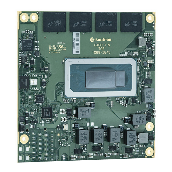
Page 20: Front View
COMe-cRP6 User Guide 3.3.3 Front View Figure 2: Front View COMe-cRP6 SoC - Processor (CPU) & Chipset (PCH) LPDDR5 memory down Optional NVMe SSD www.kontron.com 19/93... -
Page 21: Rear View
COMe-cRP6 User Guide 3.3.4 Rear View Figure 3: Rear View COMe-cRP6 COMe connectors Embedded Controller 3-pin fan connector www.kontron.com 20/93... -
Page 22: Processor (Cpu)
Core™ (@45W) Up to Up to 18MB Iris® X i5-13600HRE Graphics processor (@35W) Intel® Intel® Core™ (@45W) Up to Up to 12MB i3-13300HRE Graphics processor (@35W) Table 6: Processor lineup - 13th Gen Intel® Core™ processors (H-series 45W) www.kontron.com 21/93... - Page 23 Core™ (@15W) Up to Up to 12MB Iris® X i5-1345URE Graphics processor (@12W) Intel® Intel® Core™ (@15W) Up to Up to 10MB i3-1315URE Graphics processor (@12W) Table 8: Processor lineup - 13th Gen Intel® Core™ processors (U-series 15W) www.kontron.com 22/93...
-
Page 24: Plattform Controller Hub (Pch)
A Tj outside of the DTR range requires a cold reset but is not enforced by the hardware. The behavior is described in Intel whitepaper 814861 as DTR = Dynamic Temperature Range. Please contact Kontron Support for further information. Embedded Broad Market Industrial CPU Use Condition... -
Page 25: System Memory
PCIe #10 ETH / PCIe #5 PCIe #11 / SATA 0 SATA 0 PCIe #11 SATA 0 / PCIe #6 PCIe #12 / SATA 1 SATA 1 PCIe #12 SATA 1 / PCIe #7 Table 11: HSIO Mapping www.kontron.com 24/93... -
Page 26: Interfaces
COMe Supported Lane Configuration PCIe Gen PEG_0 PCIEX4_A_0 Gen4 PEG_1 PCIEX4_A_1 Gen4 PEG_2 PCIEX4_A_2 Gen4 PEG_3 PCIEX4_A_3 Gen4 PEG_4 (w/o NVMe) PCIEX4_B_0 Gen4 PEG_5 (w/o NVMe) PCIEX4_B_1 Gen4 PEG_6 (w/o NVMe) PCIEX4_B_2 Gen4 PEG_7 (w/o NVMe) PCIEX4_B_3 Gen4 www.kontron.com 25/93... - Page 27 The PCIEX8 lanes are only available on H-Series SKUs. The default PCIe configuration of the COMe-cRP6 is 5×1 + 2×4 (+ 1×8). To change the default PCIe configuration (5×1), a new BIOS version is required. For BIOS version information, visit Kontron’s Customer Section or contact Kontron Support.
-
Page 28: Universal Serial Bus (Usb)
SATA 6 Gb/s SATA2 - Not supported SATA3 - Not supported Table 15: SATA Port Connections 3.4.4 Ethernet The Intel® I226IT Ethernet Controller is connected to PCH HSIO Lane #9 (PCIe #10) to provide 2500BASE-T to the carrier. www.kontron.com 27/93... -
Page 29: Graphics Interfaces
HW Video Encode 4K60 10b 4:4:4 HEVC/VP9/SCC 4K60 8b 4:2:0 AVC Content Protection HDCP 2.3 Table 16: Display and Media Capabilities Please check in detail the graphics capabilities of the used CPU as these may differ depending on the SKU. www.kontron.com 28/93... -
Page 30: Audio Interfaces
LVDS (default), eDP (option) Table 17: COMe-cRP6 Graphics Interfaces Kontron recommends only using a DP-to-HDMI or DP-to-DVI passive adapter that is compliant to the DP Dual-Mode standard. If adapters are used with FET level shifter for DCC translation, display detection issues may occur. -
Page 31: Uart Serial Ports
On the COMe-cRP6 both serial ports are provided via PCIe by the On-Package PCH by default. For Windows/Linux appropriate drivers are delivered by the corresponding OS Board Support Package (BSP) stored on Kontron’s Customer Section. For other configurations like Legacy UART support please contact Kontron Support team for further details. -
Page 32: General Purpose Spi Interface
Bidirectional data path for Carrier Board SPI flash SPI_CLK SPI0_CLK Clock from the Module to Carrier Board SPI SPI_POWER Connected to V_3V3_SPI BIOS_DIS0# Inputs to control SPI_CS# routing logic that is handled by the CPLD BIOS_DIS1# Table 20: SPI on COMe-cRP6 www.kontron.com 31/93... -
Page 33: Lpc/Espi
B[8:9] LPC_DRQ[0:1] ESPI_ALERT[0:1]# LPC_SERIRQ ESPI_CS1# SUS_STAT# ESPI_RESET# ESPI_EN# Table 21: LPC/eSPI mode comparison For eSPI usage a HW modification and customized BIOS according to the customer's requirements is necessary. For further help on this please contact Kontron Support. www.kontron.com 32/93... -
Page 34: I2C
0x50 Module Embedded EEPROM (JIDA EEPROM) 0xAE 0x57 Carrier EEPROM (optional) 0x64 0x32 External RTC (optional) Table 22: I2C Bus Port Address (I2C_EXT) Internal I2C (I2C_INT) The second I2C bus is used for configuration of onboard devices only. www.kontron.com 33/93... -
Page 35: General Purpose Ios (Gpios)
The following table specifies the SMBus write address for onboard devices. 8-bit Address 7-bit Address Device 0x5C 0x2E Hardware Monitor 0xAC 0x56 Hardware Monitor (reserved) Table 23: SMBus Write Address Don't use this addresses for external devices under any circumstances. www.kontron.com 34/93... -
Page 36: Features
To power on from states S3, S4 and S5 use Power Button WakeOnLAN (S3, S4, S5) The OS must support wake up from an USB device and the carrier board must power the USB port with the standby voltage. www.kontron.com 35/93... -
Page 37: Embedded Controller - Hardware Monitor
FAN control onboard as well as to COMe. The HWM is accessible via the SMBus, see chapter 3.4.13. 3.5.3 Trusted Platform Module (TPM) The COMe-cRP6 supports a TPM chip which is directly connected to SPI0 (dedicated SPI interface from On-Package PCH). www.kontron.com 36/93... -
Page 38: Watchdog Timer (Wdt)
(SMM). As such, specific BIOS code handles the interrupt. The current BIOS handler for the watchdog SMI currently does nothing. For special requirements, contact Kontron Support A system control interrupt (SCI) is a OS-visible interrupt to be handled by the OS using AML code Might be necessary when an operating system must be started and the time Delay →... -
Page 39: Real-Time Clock (Rtc)
PCIEX4_B lanes instead of COMe PEG lanes [4:7] (see chapter 3.4.1). There are different types of NVMe SSDs available from different vendors. For further information on offered resp. released types and their particular feature set, contact Kontron Support. www.kontron.com 38/93... -
Page 40: Boot Spi Device
If ESPI_EN# selection of the carrier does not match the module configuration (LPC/eSPI) the module won’t boot. The BIOS cannot be split between two chips. Booting takes place either from the on- module SPI Flash chip or the SPI Flash device on the carrier board. www.kontron.com 39/93... -
Page 41: Embedded Eeprom
On request, a second SPI Flash device can be populated on the module for additional safety. Fail Safe Operation (automatic switchover) has to be implemented in the CPLD in that case. For further information on the Fail Safe feature and project based requirements resp. adjustments, contact Kontron Support. 3.5.8 Embedded EEPROM The module's 32 kbit serial EEPROM (formerly known as JIDA EEPROM) device is attached to the I2C bus (I2C_EXT) from the CPLD and accessible via I2C bus 8-bit address 0x0A (see chapter 3.4.11). -
Page 42: Electrical Specification
Source (LPS) of UL/IEC 60950-1 or (PS2) of UL/IEC 62368-1. To protect external power lines of peripheral devices, make sure that the wires have the right diameter to withstand the maximum available current and the enclosure of the peripheral device fulfils the fire-protection requirements of IEC/EN 62368-1. www.kontron.com 41/93... -
Page 43: Power Management
The power management options are available within the BIOS set up menu: Advance>ACPI Settings> Suspend States If power is removed, 5V can be applied to the VCC_5V_SBY pins to support the ACPI suspend-states: Suspend-to-RAM (S3) Suspend-to-disk (S4) Soft-off (S5) www.kontron.com 42/93... - Page 44 A103 Low active signal used by the ACPI operating system for a LID switch. (LID#) Sleep button Low active signal used by the ACPI operating system to bring the system to B103 (SLEEP#) sleep state or to wake it up again. Table 29: Power Supply Control Settings www.kontron.com 43/93...
-
Page 45: Power Supply Modes
S5 → S0 PWRBTN Event low → high high → low 0V → VCC high high x: Not relevant for the specific power state. There is no difference if connected or open Table 30: ATX Mode Settings www.kontron.com 44/93... - Page 46 MTBF. The minimum OFF time depends on the implemented PSU model and other electrical factors and needs to be measured individually for each case. www.kontron.com 45/93...
-
Page 47: Thermal Management
3.7 Thermal Management 3.7.1 Heatspreader Plate Assembly A heatspreader plate assembly is available from Kontron for the COMe-cRP6. The heatspreader plate assembly is NOT a heatsink. The heatspreader plate transfers heat as quickly as possible from the processor using a copper core positioned directly above the processor and a Thermal Interface Material (TIM). -
Page 48: Operating With Kontron Heatspreader Plate (Hsp) Assembly
COMe-cRP6 User Guide 3.7.3 Operating with Kontron Heatspreader Plate (HSP) Assembly The operating temperature requirements are: Maximum ambient temperature with ambient being the air surrounding the module Maximum measurable temperature on any position on the heatspreader's surface Temperature Grade Requirements At 60°C HSP temperature the MCP @ 100% load needs to run at nominal... -
Page 49: Temperature Sensors
3.7.5 Temperature Sensors The module’s processor is capable of reading its internal temperature. The on-module Hardware Monitor (HWM) chip uses an on-chip temperature sensor to measure the modules's temperature on the board. Figure 4: 1. Temperature Sensor in Processor (CPU) www.kontron.com 48/93... - Page 50 COMe-cRP6 User Guide Figure 5: 2. Temperature Sensor in Hardware Monitor (HWM) www.kontron.com 49/93...
-
Page 51: On-Module Fan Connector
3.7.6 On-Module Fan Connector The module's fan connector powers, controls and monitors an external fan. To connect a standard 3- pin connector fan to the module, use Kontron's fan cable (see chapter 3.2). Figure 6: 1. On-Module 3-Pin Fan Connector www.kontron.com... - Page 52 FAN_TACH_IN# Fan input voltage from COMe connector Input V_FAN 12 V ±10% (max.) across module input range PWR Power GND Table 33: Fan Connector Pin Assignment Always check the fan specification according to the limitations of the supply current and supply voltage. www.kontron.com 51/93...
-
Page 53: Mechanical Specification
COMe-cRP6 User Guide 3.8 Mechanical Specification The COMe-cRP6 is compatible with the COM Express® mechanical specification. 3.8.1 Module Dimensions The COMe compact module dimensions are 95 mm x 95 mm (3.7“ x 3.7“). Figure 7: Module Dimensions www.kontron.com 52/93... -
Page 54: Module Height
The heatspreader plate works as a COM Express® standard thermal interface and must be used with a heatsink or external cooling device to maintain the heatspreader plate at proper operating temperatures. For heatspreader plate drawings and 3D models check our Customer Section. www.kontron.com 53/93... -
Page 55: Environmental Specification
Relative Humidity 93 % @40°C, non-condensing Shock Non-operating shock test (half-sinusoidal, 11ms, 15g) (according to IEC 60068-2-27) Vibration Non-operating vibration (sinusoidal, 10 Hz to 2000 Hz, +/- 0.15 (according to IEC 60068-2-6) mm, 2 g) Table 34: Environmental Specification www.kontron.com 54/93... -
Page 56: Compliance
COMe-cRP6 User Guide 3.10 Compliance The COMe-cRP6 complies with the following or the latest status thereof. If modified, the prerequisites for specific approvals may no longer apply. For more information, contact Kontron Support. Europe - CE Mark 2014/30/EU: Electromagnetic Compatibility... - Page 57 COMe-cRP6 User Guide If the product is modified, the prerequisites for specific approvals may no longer apply. Kontron is not responsible for any radio television interference caused by unauthorized modifications of the delivered product or the substitution or attachment of connecting cables and equipment other than those specified by Kontron.
-
Page 58: Mtbf
Estimated RTC battery life (as opposed to battery failures) is not accounted for and needs to be considered separately. Battery life depends on both temperature and operating conditions. When the module is connected to external power, the only battery drain is from leakage paths. www.kontron.com 57/93... -
Page 59: Come Interface Connector
A & B on the primary connector J1 and row C & D on the secondary connector J2. Figure 9: COMe Interface Connectors COMe interface connector (J1) COMe interface connector (J2) Connector J1 - Pin A1 Connector J2 - Pin D1 www.kontron.com 58/93... -
Page 60: Connecting Come Interface Connector To Carrier Board
3.3 V Input (5 V tolerance) PU/PD Pull-Up/Pull-Down Resistor Output Analog Power Connection Output Open Drain Differential Pair Differentiator Table 38: General Signal Description The pin assignment tables list the internal pull-ups (PU) or pull-downs (PD) implemented by the chip vendors. www.kontron.com 59/93... -
Page 61: Connector J1 Pinout
SATA Transmit Pair 2 + — — SATA2_TX- SATA Transmit Pair 2 - — — SUS_S5# Soft-off Indicator O-3.3 PD 100k — SATA2_RX+ SATA Receive Pair 2 + — — SATA2_RX- SATA Receive Pair 2 - — — www.kontron.com 60/93... - Page 62 USB 2.0 Data Pair Port 2 PD 14.25k to USB2+ DP-I/O — 24.8k in PCH USB Overcurrent PU 10k 3.3V USB_2_3_OC# I-3.3 — Indicator Port 2/3 (S5) USB 2.0 Data Pair Port 0 PD 14.25k to USB0– DP-I/O — – 24.8k in PCH www.kontron.com 61/93...
- Page 63 General Purpose Input 2 I-3.3 — (S0) PCI Express Lane 0 AC coupled on PCIE_TX0+ DP-O — Transmit + module (220nF) PCI Express Lane 0 AC coupled on PCIE_TX0- DP-O — Transmit - module (220nF) Power Ground PWR GND — — www.kontron.com 62/93...
- Page 64 — Ohm series termination General Purpose Output GPO0 O-3.3 PD 100k — On module 10 SPI_CLK SPI Clock O-3.3 PD 100k Ohm series termination On module 10 SPI_MOSI SPI Master Out Slave In O-3.3 — Ohm series termination www.kontron.com 63/93...
- Page 65 — — (8.5-20V) 8.5-20V Main Input Voltage A108 VCC_12V — — (8.5-20V) 8.5-20V Main Input Voltage A109 VCC_12V — — (8.5-20V) 8.5-20V A110 GND Power Ground PWR GND — — Table 39: Connector J1 Pins A1 - A110 www.kontron.com 64/93...
-
Page 66: Pins B1 - B110
AC coupled on SATA1_TX- SATA 1 Transmit Pair - DP-O — module (10nF) Suspend Status / eSPI O-3.3 / SUS_STAT#/ESPI_RESET# PD 10k Default LPC Reset O-1.8 AC coupled on SATA1_RX+ SATA 1 Receive Pair + DP-I — module (10nF) www.kontron.com 65/93... - Page 67 USB 2.0 Data Pair Port 7 PD 14.25k to USB7+ DP-I/O — 24.8k in PCH USB Overcurrent PU 10k 3.3V USB_4_5_OC# I-3.3 — Indicator Port 4/5 (S5) USB 2.0 Data Pair Port 5 PD 14.25k to USB5- DP-I/O — – 24.8k in PCH www.kontron.com 66/93...
- Page 68 PCI Express Lane 2 PCIE_RX2+ DP-I — — Receive + PCI Express Lane 2 PCIE_RX2- DP-I — — Receive - General Purpose Output GPO3 O-3.3 PD 100k — PCI Express Lane 1 PCIE_RX1+ DP-I — — Receive + www.kontron.com 67/93...
- Page 69 — (S5) single supply mode) Optional (not PWR 5V necessary in VCC_5V_SBY 5V Standby — (S5) single supply mode) PU 10k 3.3V BIOS_DIS1# BIOS Selection Strap 1 I-3.3 — (S5) CRT_RED / Analog Video VGA_RED — — RGB-RED www.kontron.com 68/93...
- Page 70 (8.5-20V) 8.5-20V Main Input Voltage B106 VCC_12V — — (8.5-20V) 8.5-20V Main Input Voltage B107 VCC_12V — — (8.5-20V) 8.5-20V Main Input Voltage B108 VCC_12V — — (8.5-20V) 8.5-20V Main Input Voltage B109 VCC_12V — — (8.5-20V) 8.5-20V www.kontron.com 69/93...
- Page 71 COMe-cRP6 User Guide Signal Description Type Termination Comment B110 GND Power Ground — — Table 40: Connector J1 Pins B1 - B110 www.kontron.com 70/93...
-
Page 72: Connector J2 Pinout
USB Super C13 USB_SSRX3+ Speed Receive 3 DP-I — — C14 GND Power Ground — — USB4 not supported by default - Project USB4 Side-Band C15 USB4_1_LSTX O-3.3 PD 1M based HW and TX Interface BIOS implementation needed www.kontron.com 71/93... - Page 73 C26 SML0_DAT Management IO33-OD based HW and (S5) Link 0 Data BIOS implementation needed USB4 not supported by System default - Project PU 768R 3.3V C27 SML1_CLK Management IO33-OD based HW and (S5) Link 1 Clock BIOS implementation needed www.kontron.com 72/93...
- Page 74 O-3.3 PD 1M based HW and TX interface BIOS implementation needed DDI3 C36 DDI3_CTRLCLK_AUX+ I/O-3.3 PD 100k — CTRLCLK/AUX+ DDI3 PU 100k 3.3V C37 DDI3_CTRLDATA_AUX- I/O-3.3 — CTRLDATA/AUX- (S0) DDI3 DDC/AUX C38 DDI3_DDC_AUX_SEL I-3.3 PD 1M — select www.kontron.com 73/93...
- Page 75 Receive + PEG Lane 3 C62 PEG_RX3- DP-I — — Receive - C63 GND Power Ground — — C64 GND Power Ground — — Optionally PEG Lane 4 C65 PEG_RX4+ DP-O — connected to Receive + on-board NVMe www.kontron.com 74/93...
- Page 76 Power Ground — — C84 GND Power Ground — — PEG Lane 10 Only on H- C85 PEG_RX10+ DP-O — Receive + series SKUs PEG Lane 10 Only on H- C86 PEG_RX10- DP-O — Receive - series SKUs www.kontron.com 75/93...
- Page 77 8.5-20V (8.5-20V) Main Input C105 VCC_12V Voltage — — 8.5-20V (8.5-20V) Main Input C106 VCC_12V Voltage — — 8.5-20V (8.5-20V) Main Input C107 VCC_12V Voltage — — 8.5-20V (8.5-20V) Main Input C108 VCC_12V Voltage — — 8.5-20V (8.5-20V) www.kontron.com 76/93...
- Page 78 COMe-cRP6 User Guide Signal Description Type Termination Comment Main Input C109 VCC_12V Voltage — — 8.5-20V (8.5-20V) C110 GND Power Ground — — Table 41: Connector J2 Pins C1 - C110 www.kontron.com 77/93...
-
Page 79: Pins D1 - D110
— Transmit 3 + (100nF) D14 GND Power Ground — — USB4 not supported by Display Port default - Project AUX+ or D15 DDI1_CTRLCLK_AUX+/\\USB4_1_AUX+ I/O-3.3 PD 100k based HW and Display Data BIOS Channel Clock implementation needed www.kontron.com 78/93... - Page 80 BIOS implementation needed USB4 not supported by DDI1 Pair 0 - / default - Project USB4 1 Data D27 DDI1_PAIR0-/\\USB4_1_SSTX0- DP-O — based HW and Transmit Pair BIOS implementation needed Reserved for D28 RSVD — — future use www.kontron.com 79/93...
- Page 81 I-3.3 PD 1M based HW and Interface BIOS implementation needed USB4 not supported by DDI1 Pair 3 + default - Project D36 DDI1_PAIR3+/\\USB4_1_SSRX1+ / USB4 1 Data DP-I/O — based HW and Receive Pair 1 BIOS implementation needed www.kontron.com 80/93...
- Page 82 I-3.3 PD 100k — Detect D45 GND Power Ground — — USB4 not supported by DDI2 Pair 2 + default - Project / USB4 2 Data D46 DDI2_PAIR2+/\\USB4_2_SSTX1+ DP-O — based HW and Transmit Pair BIOS implementation needed www.kontron.com 81/93...
- Page 83 — Transmit + (220nF) AC coupled on PEG Lane 2 D59 PEG_TX2- DP-O module — Transmit - (220nF) D60 GND Power Ground — — AC coupled on PEG Lane 3 D61 PEG_TX3+ DP-O module — Transmit + (220nF) www.kontron.com 82/93...
- Page 84 AC coupled on PEG Lane 8 Only on H-series D78 PEG_TX8+ DP-O module Transmit + SKUs (220nF) AC coupled on PEG Lane 8 Only on H-series D79 PEG_TX8- DP-O module Transmit - SKUs (220nF) D80 GND Power Ground — — www.kontron.com 83/93...
- Page 85 Power Ground — — AC coupled on PEG Lane 14 Only on H-series D98 PEG_TX14+ DP-O module Transmit + SKUs (220nF) AC coupled on PEG Lane 14 Only on H-series D99 PEG_TX14- DP-O module Transmit - SKUs (220nF) www.kontron.com 84/93...
- Page 86 D107 VCC_12V Voltage — — 8.5-20V (8.5-20V) Main Input D108 VCC_12V Voltage — — 8.5-20V (8.5-20V) Main Input D109 VCC_12V Voltage — — 8.5-20V (8.5-20V) D110 GND Power Ground — — Table 42: Connector J2 Pins D1 - D110 www.kontron.com 85/93...
-
Page 87: Uefi Bios
COMe-cRP6 User Guide 5. UEFI BIOS 5.1 Starting the UEFI BIOS The COMe-cRP6 uses a Kontron-customized, pre-installed and configured version of AMI Aptio® V BIOS based on the Unified Extensible Firmware Interface (UEFI) specification and the Intel® Platform Innovation Framework for EFI. -
Page 88: Navigating The Uefi Bios
Use the left and right arrow keys to select the Setup menu. Each Setup menu provides two main frames. The left frame displays all available functions and configurable ones are displayed in blue. Functions displayed in grey provide information about the status or the operational configuration. www.kontron.com 87/93... -
Page 89: Getting Help
COMe-cRP6 User Guide 5.4 Getting Help The right frame displays a help window. The help window provides an explanation of the respective function. www.kontron.com 88/93... -
Page 90: Uefi Shell
COMe-cRP6 User Guide 5.5 UEFI Shell The Kontron UEFI BIOS features a built-in and enhanced version of the UEFI Shell. For a detailed description of the available standard shell scripting, refer to the EFI Shell User Guide. For a detailed description of the available standard shell commands, refer to the EFI Shell Command Manual. -
Page 91: Uefi Shell Scripting
Initially searches for Kontron flash-stored startup script If there is no Kontron flash-stored startup script present, then the UEFI-specified startup.nsh script is used. This script must be located on the root of any of the attached FAT-formatted disk... - Page 92 RMA number. The buyer accepts responsibility for all freight charges for the return of goods to Kontron’s designated facility. Kontron will pay the return freight charges back to the buyer’s location in the event that the equipment is repaired or replaced within the stipulated warranty period.
- Page 93 fill out the above information in the RMA Request form for each product. Send the completed RMA-Request form to the fax or email address given below at Kontron Europe GmbH. Kontron will provide an RMA-Number.
- Page 94 The following table shows the revision of this document. Revision Author Date Comment 2023-10-19 Initial preliminary release 2023-10-27 Adapted paragraph regarding PCI Express Graphics 2023-11-24 Added MTBF value Updated pin-out list; Added DTR information in chapter 3.3.5; 2024-04-18 Document release Table 44: Document Revision Table www.kontron.com 93/93...
Need help?
Do you have a question about the COMe-cRP6 E2 and is the answer not in the manual?
Questions and answers