Table of Contents
Advertisement
Quick Links
Advertisement
Table of Contents

Subscribe to Our Youtube Channel
Related Manuals for Kontron COMe-bCL6


Summary of Contents for Kontron COMe-bCL6
- Page 1 USER GUIDE COMe-bCL6 User Guide Rev 2.0 Doc. ID: 1062-1415 www.kontron.com // 1...
- Page 2 COMe-bCL6 - User Guide Rev 2.0 This page has been intentionally left blank www.kontron.com // 2...
- Page 3 Kontron with respect to technical processes described in the user guide or any product characteristics set out in the user guide. Kontron assumes no responsibility or liability for the use of the described product(s), conveys no license or title under any patent, copyright or mask work rights to these products and makes no representations or warranties that these products are free from patent, copyright or mask work right infringement unless otherwise specified.
- Page 4 ENVIRONMENTAL DAMAGE (COLLECTIVELY, "HIGH RISK APPLICATIONS"). You understand and agree that your use of Kontron devices as a component in High Risk Applications is entirely at your risk. To minimize the risks associated with your products and applications, you should provide adequate design and operating safeguards.
- Page 5 Kontron sells products worldwide and declares regional General Terms & Conditions of Sale, and Purchase Order Terms & Conditions. Visit http://www.kontron.com/terms-and-conditions. For contact information, refer to the corporate offices contact information on the last page of this user guide or visit our website CONTACT US.
- Page 6 If you have any difficulties using this user guide, discover an error, or just want to provide some feedback, contact Kontron support. Detail any errors you find. We will correct the errors or problems as soon as possible and post the revised user guide on our website.
-
Page 7: Symbols
COMe-bCL6 - User Guide Rev 2.0 Symbols The following symbols may be used in this user guide. DANGER indicates a hazardous situation which, if not avoided, will result in death or serious injury. WARNING indicates a hazardous situation which, if not avoided, could result in death or serious injury. - Page 8 Therefore, in the interest of your own safety and of the correct operation of your new Kontron product, you are requested to conform to the following guidelines.
- Page 9 General Instructions on Usage In order to maintain Kontron’s product warranty, this product must not be altered or modified in any way. Changes or modifications to the product, that are not explicitly approved by Kontron and described in this user guide or received from Kontron Support as a special handling instruction, will void your warranty.
-
Page 10: Table Of Contents
COMe-bCL6 - User Guide Rev 2.0 Table of Contents Symbols ..........................................7 Table of Contents......................................10 List of Tables ........................................12 List of Figures ........................................13 Introduction ......................................15 1.1. Product Description....................................15 1.2. Product Naming Clarification ................................15 1.3. COM Express® Documentation ................................15 1.4. - Page 11 2.4.7.2. Single Supply Mode..................................38 2.5. Thermal Management ................................... 39 2.5.1. Heatspreader and Cooling Solutions .............................. 39 2.5.2. Operating with Kontron Heatspreader Plate (HSP) Assembly ..................... 39 2.5.3. Operating without Kontron Heatspreader Plate Assembly ....................39 2.5.4. On-board Fan Connector ................................... 39 2.6.
-
Page 12: List Of Tables
About Kontron – Member of the S&T Group ............................100 List of Tables Table 1: Pin Assignment of Type 6 and COMe-bCL6 ..........................16 Table 2: Commercial Grade Modules (0°C to +60°C) ..........................17 Table 3: R E2S Modules (R E2S, -40°C to +85°C) ............................ 18 Table 4: Product Specific Accessories ............................... -
Page 13: List Of Figures
Table 60: Security Setup Menu Functions ............................... 90 Table 61: Boot Setup Menu Functions ..............................92 Table 62: Save and Exit Setup Menu Functions............................. 93 List of Figures Figure 1: Block Diagram COMe-bCL6 ................................. 22 Figure 2: Front View COMe-bCL6 ................................23 www.kontron.com // 13... - Page 14 COMe-bCL6 - User Guide Rev 2.0 Figure 3: Bottom View COMe-bCL6 ................................24 Figure 4: MTBF Temperature de-Rating ..............................43 Figure 5: Module Dimensions ..................................44 Figure 6: Module Height ....................................44 Figure 7: X1A and X1B COMe Interface Connectors ..........................56 Figure 8: Main Setup Menu....................................
-
Page 15: 1/ Introduction
1.1. Product Description Kontron's Computer-on-Module COMe-bCL6 is a COM Express® Basic Type 6 pinout based on the Intel® 8 Generation Core ™/Xeon® processors. The COMe-bCL6 supports additional communication interfaces via a separate Chipset (CM246/QM370 PCH). Due to Intel’s 14nm technology, the processor offers increased efficiency and performance with TDP as low as 25 to 45 W for quad-core chips and 25 to 45 W for six cores. -
Page 16: Com Express® Functionality
COM Express® Functionality All Kontron COM Express® basic and compact modules contain two 220-pin connectors; each of which has two rows called row A & B on the primary connector and row C & D on the secondary connector. The COM Express® Computer- On-Module (COM) features the following maximum amount of interfaces according to the PCI Industrial Computer Manufacturers Group (PICMG) module pinout type. -
Page 17: 2/ Product Specification
2/ Product Specification 2.1. Module Variants The COM Express® basic sized, Computer-on-Module COMe-bCL6, uses pinout Type 6 and is compatible with the PICMG specification COM.0 Rev. 3.0. The COMe-bCL6 is available in different variants to cover demands in performance, price and power. -
Page 18: Extended Temperature Grade Modules (E1, -25 °C To +75 °C)
2.1.3. R E2S Modules (R E2S, -40°C to +85°C) The following table provides a list of R E2S modules available with Kontron Rapid Shutdown support and E2 temperature grade (-40°C to +85°C) by screening. For further information regarding the screening process contact Kontron Support Table 3: R E2S Modules (R E2S, -40°C to +85°C) -
Page 19: Accessories
DDR4 non-ECC SO-DIMM, Rapid Shutdown, industrial temperature grade 2.2. Accessories The following tables provide a list of specific and general COMe-bCL6 accessories. For more information, contact your local Kontron sales representative or Kontron Inside Sales. Table 4: Product Specific Accessories Part Number... -
Page 20: Table 5: Come Type 6 Specific Accessories
COMe-bCL6 - User Guide Rev 2.0 Table 5: COMe Type 6 Specific Accessories Part Number COMe Carrier Project Code Comment 38115-0000-00-x COM Express® ADTI Thin-mITX Carrier with 5 mm Reference Carrier-i Type 6 COMe connector 38116-0000-00-5 COM Express® Eval Carrier2 Type... -
Page 21: Table 7: Memory Modules
COMe-bCL6 - User Guide Rev 2.0 Table 7: Memory Modules Part Number Memory (validated reference types) 97017-4096-27-0 DDR4-2666 SODIMM 4GB_COM DDR4-2666, 4GB, 260P, 1333MHz, PC4-2666 SODIMM 97017-8192-27-0 DDR4-2666 SODIMM 8GB_COM DDR4-2666, 8GB, 260P, 1333MHz, PC4-2666 SODIMM 97017-1600-27-0 DDR4-2666 SODIMM 16GB_COM... -
Page 22: Functional Specification
COMe-bCL6 - User Guide Rev 2.0 2.3. Functional Specification 2.3.1. Block Diagram COMe-bCL6 The following figure displays the system block diagram applicable to all COMe-bCL6 modules. Figure 1: Block Diagram COMe-bCL6 www.kontron.com // 22... -
Page 23: Front And Bottom View
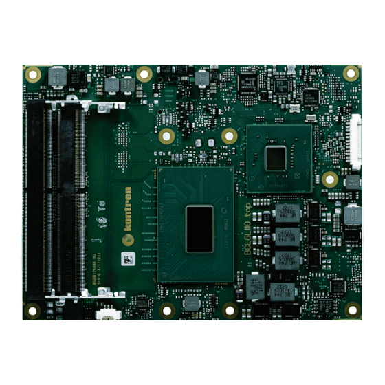
COMe-bCL6 - User Guide Rev 2.0 2.3.2. Front and Bottom View 2.3.2.1. Front View Figure 2: Front View COMe-bCL6 2x SO-DIMM slots Processor Fan connector www.kontron.com // 23... -
Page 24: 2.3.2.2. Bottom View
COMe-bCL6 - User Guide Rev 2.0 2.3.2.2. Bottom View Figure 3: Bottom View COMe-bCL6 2x COMe interfaces X1A and X1B Place for additional SO-DIMM slots Place for additional NVMe www.kontron.com // 24... -
Page 25: Technical Data
COMe-bCL6 - User Guide Rev 2.0 2.3.3. Technical Data Table 8: Technical Data Function Definition Compliance COM Express® basic, Pin-out Type 6 Dimensions (H X W) 125 x 95 mm Intel 8 Generation Core/Xeon Series, Package: BGA1440: Intel® Xeon® E-2276ME/ML, Intel® Xeon® E-2254ME/ML, Intel® Core™ i7- 9850HE/HL, Intel®... -
Page 26: Processor
COMe-bCL6 - User Guide Rev 2.0 2.3.4. Processor The Intel® 8 Generation Core™ series product family uses the 14 nm process technology, with 42 mm x 28 mm package size and BG1440 socket. In general, the processors supports the following technologies: ... -
Page 27: Table 9: Specifications Of The Come-Bcl6 Processor Variants
COMe-bCL6 - User Guide Rev 2.0 Table 9: Specifications of the COMe-bCL6 Processor Variants Cores/ Frequency Processor L3-Cache TDP/T Graphics Junction Threads nom./Turbo Intel® Xeon® E- 6/12 2.8/4.5 GHz 12 MByte 45 W/100°C UHD-Graphics P630 2276ME Intel® Xeon® E- 6/12 2.0/4.2 GHz... -
Page 28: Chipset
COMe-bCL6 - User Guide Rev 2.0 2.3.5. Chipset The COMe-bCL6 is a two-chip solution implementing the H CPU and CM246, QM370 and optional HM370 Platform Controller Hub. 2.3.5.1. Platform Controller Hub (PCH) The following table lists the PCH QM370 and CM246 PCH features. -
Page 29: Trusted Platform Module (Tpm)
COMe-bCL6 - User Guide Rev 2.0 2.3.8. Trusted Platform Module (TPM) The SLB 9670 is a Trusted Platform Module and is based on advanced hardware security technology. This TPM implementation has achieved CC EAL4+ certification and serves as a basis for other TPM products and firmware upgrades. -
Page 30: Pci Express Graphics 3.0 (Peg)
COMe-bCL6 - User Guide Rev 2.0 2.3.13. PCI Express Graphics 3.0 (PEG) Table 14: PCI Express Graphics 3.0 COMe Lane 1x16 1x16 1x8+2x4 1x8+2x4 (Default) Reversed Reversed Reversed PEG0 PEG1 PEG2 PEG3 PEG4 PEG5 PEG6 PEG7 PEG8 PEG9 PEG10 PEG11... -
Page 31: Serial Ata 3.0
If the LAN-Cable is disconnected, the ULP (Ultra Low Power) driver featured in Windows 10 can cause undefined LED behavior. To disable ULP use the “Intel ULPEnable-Utility 1.3”. For more information refer to the EMD Customer Section or contact Kontron Support. www.kontron.com... -
Page 32: Graphic Interfaces
COMe-bCL6 - User Guide Rev 2.0 2.3.17. Graphic Interfaces Up to four independent Digital Display Interfaces can be used simultaneously and in combination, to implement an independent or cloned display configuration. 3x DP 1.2 with Audio 1x eDP 1.4 or LVDS ... -
Page 33: Inter-Integrated Circuit (I2C)-Bus
COMe-bCL6 - User Guide Rev 2.0 COMe Connector HDA_SDIN[0:1] HDA_SDI[0:1] HDA_SDIN2 2.3.20. Inter-Integrated Circuit (I2C)-Bus Two I2C Buses generated by. I2C is used for attaching lower-speed peripheral ICs to processors and microcontrollers in short-distance, intra-board communication. 2.3.21. Power Supply Control Settings The power supply control settings are set in the BIOS and enable the module to shut down, rest and wake from standby properly. -
Page 34: Uart Serial Ports
COMe-bCL6 - User Guide Rev 2.0 2.3.24. UART Serial Ports Table 23: UART Signals COMe Signal EC/kCPLD function SER0_TX po_uart_tx[0] SER0_RX po_uart_rx[0] SER1_TX po_uart_tx[1] SER1_RX po_uart_rx[1] 2.3.25. BIOS/Software Features Table 24: BIOS and Software Features Feature Remark Supported BIOS EFI... -
Page 35: Electrical Specification
Power Supply Voltage The supply voltage is applied through the VCC pins (VCC) of the module connector. The COMe-bCL6 supports a power supply input from 8.5 V to 20 V and operation in both single supply and ATX power supply mode. -
Page 36: Table 29: Power Supply And Management
Module shall power on automatically in single supply operation when VCC is connected (with correct BIOS settings) Power Features Kontron Rapid Shutdown feature (for R E2S variants) LID and Sleep LID and Sleep signal for external Sleep button and LID switch... -
Page 37: Power Supply Control Settings
Soft-off state (S5) The Wake-Up event (S0) requires VCC power, as the board is running. 2.4.6. Power Supply Control Settings The following table provides a description of the COMe-bCL6’s power supply control settings. Table 31: Power Supply Control Settings Feature Remark... -
Page 38: Power Supply Modes
COMe-bCL6 - User Guide Rev 2.0 2.4.7. Power Supply Modes 2.4.7.1. ATX Mode By connecting an ATX power supply with VCC and 5 VSB, PWR_OK is set to low and VCC is off. Pressing the power button sets the ATX PSU setting PWR_OK to high and powers VCC. The PS_ON# signal generated by SUS_S3# (A15) indicates that the system is in Suspend to RAM state. -
Page 39: Thermal Management
Heatspreader and Cooling Solutions A heatspreader plate assembly is available from Kontron for the COMe-bCL6. The heatspreader plate on top of this assembly is NOT a heat sink. The heatspreader works as a COM Express® standard thermal interface to be use with a heat sink or external cooling devices. -
Page 40: Table 36: Electrical Characteristics Of The Fan Connector
COMe-bCL6 - User Guide Rev 2.0 Signal Description Type Power GND To connect a standard 3-pin connector fan to the module, use one of the following adaptor cables: KAB-HSP 200 mm (PN 96079-0000-00-0) KAB-HSP 40 mm (PN 96079-0000-00-2) If the input voltage is below 13 V, the maximum supply current to the on-module fan connector is 350 mA. -
Page 41: Environmental Specification
COMe-bCL6 - User Guide Rev 2.0 2.6. Environmental Specification 2.6.1. Temperature Kontron defines the following temperature grades for Computer-on-Modules. For more information on the available temperature grades for the COMe-bCL6, see Chapter 2.1 Module Variants. Table 37: Temperature Grade Specifications Storage Validated Input... -
Page 42: Standards And Certifications
COMe-bCL6 - User Guide Rev 2.0 2.7. Standards and Certifications The COMe-bCL6 complies with the following standards and certifications. All Peripheral interfaces intended for connection to external equipment are ESD/EMI protected. Table 39: Standards and Certifications Emission EN55032:2015 Class B... -
Page 43: Mtbf
(as opposed to battery failures) is not accounted for in the above figure and needs to be considered separately. Battery life depends on both temperature and operating conditions. When the Kontron unit has external power, the only battery drain is from leakage paths. -
Page 44: Mechanical Specification
Figure 6: Module Height Cooling solutions provided by Kontron for basic sized Computer-on-Modules are 27 mm in height from module bottom to heatsink top. Universal Cooling solutions to be mounted on the heatspreader are 14.3 mm in height for an overall height of 27.3 mm from module bottom to heatsink top. -
Page 45: 3/ Features And Interfaces
The SPI interface can only be used with a SPI flash device to boot from the external BIOS on the baseboard. 3.2.1. SPI boot The COMe-bCL6 supports boot from a 16 MB 3V serial external SPI Flash. Pin A34 (BIOS_DIS0#) and pin B88 (BIOS_DIS1#) configure the SPI Flash as follows: Table 41: SPI Boot Pin Configuration Configuration... -
Page 46: Using An External Spi Flash
COMe-bCL6 - User Guide Rev 2.0 BIOS does not support being split between two chips. Booting takes place either from the module SPI or from the baseboard SPI. The following table provides a list of supported SPI Boot Flash types for the 8-SOIC package. -
Page 47: External Spi Flash On Modules With Intel® Me - In The Prd
SMART_CHARGER 0x0A SMART_SELECTOR 0x0B SMART_BATTERY 3.4. Fast I2C Fast I2C supports transfer between components on the same board. The COMe-bCL6 features an on-board I2C controller connected to the LPC Bus. The I2C controller supports: Multimaster transfers Clock stretching ... -
Page 48: Triple Staged Watchdog Timer (Wdt)
Possible fault conditions are a hang, or neglecting to service the watchdog regularly. Such as writing a “service pulse” to it, also referred to as “kicking the dog”, “petting the dog”, “feeding the watchdog” or “triggering the watchdog”. The COMe-bCL6 offers a watchdog that works with three stages that can be programmed independently and used stage by stage. -
Page 49: Real Time Clock (Rtc)
Kontron APPROTECT is a combined hardware and software solution that includes an embedded hardware security chip on and a software framework to provide full protection for your application. The security solution is connected to PCH USB2 Port 9. The COMe-bCL6 includes an integrated security module connected to USB2 Port 9, supporting the following features: ... -
Page 50: Shutdown Input Circuit Details
Additionally, by using the UVLO mechanism in the design of the R E2S module, Kontron minimizes the risk of inadvertently affecting the standard power sequencing logic for such R E2S modules. Two of the switching regulators do not require the 5 V supply for operation, and in those two cases it will be necessary to clamp the enable inputs to ground when shutdown begins. -
Page 51: 4/ System Resources
COMe-bCL6 - User Guide Rev 2.0 4/ System Resources 4.1. Memory Area The following table specifies the memory address range and COMe-bCL6 memory usage. Table 45: Designated memory Locations Address Range (hex) Size Project Usage Address range (hex) Size Project usage... -
Page 52: I/O Address Map
I/O Address Map The I/O port addresses of the COMe-bCL6 are functionally identical to a standard PC/AT. All addresses not mentioned in this table should be available. We recommend that you do not use I/O addresses below 0100h with additional hardware for compatibility reasons, even if the I/O address is available. - Page 53 COMe-bCL6 - User Guide Rev 2.0 I/O Address Range General Usage Project Usage 200-207 Gameport Low Gameport Low 208-20F Gameport High Gameport High 220-22F Soundblaster® Not used ISA PnP Not used 278-27F Parallel port LPT2 Not used 295-296 Hardware monitor (Winbond default)
-
Page 54: Legacy Interrupt (Irq) Lines
COMe-bCL6 - User Guide Rev 2.0 4.3. Legacy Interrupt (IRQ) lines The following table specifies the Interrupt lines and the device connected to the Interrupt line. It also states which Interrupt lines are available for new devices. Table 47: List of Interrupt Requests... -
Page 55: System Management (Sm) Bus
COMe-bCL6 - User Guide Rev 2.0 4.6. System Management (SM) Bus The 8-bit SMBus address uses the LSB (Bit 0) for the direction of the device. Bit0 = 0 defines the write address Bit0 = 1 defines the read address The 8-bit address listed below shows the write address for all devices. -
Page 56: 5/ Interface Connectors X1A And X1B
COMe-bCL6 - User Guide Rev 2.0 5/ Interface Connectors X1A and X1B The COMe-bCL6 is a COM Express® basic module containing two 220-pin connectors; each with two rows called row A & B on primary connector and row C & D on secondary connector. -
Page 57: X1A And X1B Pin Assignment
Connector X1A Row A1 – A110 The following section describes the signals found on COM Express™ Type 6 connectors used for Kontron modules. The pinout of the modules complies with COM Express Type 6 Rev. 3.0. The table below describes the terminology used in this section. - Page 58 COMe-bCL6 - User Guide Rev 2.0 Signal Description Type Termination Comment GBE0_LINK1000# Ethernet Speed LED GBE0_MDI2- Ethernet Media Dependent DP-I/O Interface 2 - GBE0_MDI2+ DP-I/O Ethernet Media Dependent Interface 2 + GBE0_LINK# LAN Link LED GBE0_MDI1- Ethernet Media Dependent DP-I/O...
- Page 59 COMe-bCL6 - User Guide Rev 2.0 Signal Description Type Termination Comment THRMTRIP# Thermal Trip O-3.3 PU 10k 3.3V Thermal Trip (S0) Event, transition to S5 indicator USB6- USB 2.0 Data Pair Port 6 – DP-I/O PD 14.25k to 24.8k in USB6+ USB 2.0 Data Pair Port 6 +...
- Page 60 COMe-bCL6 - User Guide Rev 2.0 Signal Description Type Termination Comment PCIE_TX3- PCI Express Lane 3 Transmit - DP-O Power Ground PWR GND PCIE_TX2+ PCI Express Lane 2 Transmit + DP-O PCIE_TX2- PCI Express Lane 2 Transmit - DP-O GPI1 General Purpose Input 1 I-3.3...
- Page 61 COMe-bCL6 - User Guide Rev 2.0 Signal Description Type Termination Comment Power Ground PWR GND SPI_POWER 3.3V Power Output Pin for external O-3.3 100mA (max.) SPI flash SPI_MISO SPI Master IN Slave OUT I-3.3 PU 20k +/- All SPI signals...
-
Page 62: Connector X1A Row B 1 - B 110
COMe-bCL6 - User Guide Rev 2.0 Signal Description Type Termination Comment A103 LID# LID Switch Input I-3.3 PU 47k 3.3V 20V protection (S5) circuit implemented on module A104 VCC_12V Main Input Voltage (4.75-20V) PWR 4.75- A105 VCC_12V Main Input Voltage (4.75-20V) PWR 4.75-... - Page 63 COMe-bCL6 - User Guide Rev 2.0 Signal Description Type Termination Comment PWRBTN# Power Button I-3.3 PU 3k32 3.3V (S5) SMB_CLK SMBUS Clock O-3.3 PU 3k9 3.3V (S5) SMB_DAT SMBUS Data I/O-3.3 PU 3k9 3.3V (S5) SMB_ALERT# SMBUS Alert I/O-3.3 PU 2k26 3.3V (S5)
- Page 64 COMe-bCL6 - User Guide Rev 2.0 Signal Description Type Termination Comment USB_4_5_OC# USB Overcurrent Indicator Port 4/5 I-3.3 PU 10k 3.3V (S5) USB5- USB 2.0 Data Pair Port 5 – DP-I/O PD 14.25k to 24.8k in USB5+ USB 2.0 Data Pair Port 5 + DP-I/O PD 14.25k to...
- Page 65 COMe-bCL6 - User Guide Rev 2.0 Signal Description Type Termination Comment WAKE1# General Purpose Wake Event I-3.3 PU 10k 3.3V (S5) PCIE_RX0+ PCI Express Lane 0 Receive + DP-I PCIE_RX0- PCI Express Lane 0 Receive - DP-I Power Ground PWR GND...
-
Page 66: Connector X1B Row C 1 - C 110
COMe-bCL6 - User Guide Rev 2.0 Signal Description Type Termination Comment SPI_CS# SPI Chip Select O-3.3 RSVD Reserved for future use RSVD Reserved for future use B100 Power Ground PWR GND B101 FAN_PWMOUT Fan PWM Output O-3.3 20V protection circuit... - Page 67 COMe-bCL6 - User Guide Rev 2.0 Signal Description Type Termination Comment Power Ground USB_SSRX1- USB Super Speed Receive DP-I USB_SSRX1+ USB Super Speed Receive DP-I Power Ground USB_SSRX2- USB Super Speed Receive DP-I USB_SSRX2+ USB Super Speed Receive DP-I Power Ground...
- Page 68 COMe-bCL6 - User Guide Rev 2.0 Signal Description Type Termination Comment DDI2_DDC_AUX_SEL DDI2 DDC/AUX select I-3.3 PD 1M RSVD Reserved for future use DDI3_CTRLCLK_AUX+ DDI3 CTRLCLK/AUX+ I/O- PD 100k DDI3_CTRLDATA_AUX- DDI3 CTRLDATA/AUX- I/O- PU 100k 3.3V (S0) DDI3_DDC_AUX_SEL DDI3 DDC/AUX select I-3.3...
- Page 69 COMe-bCL6 - User Guide Rev 2.0 Signal Description Type Termination Comment Power Ground PEG_RX6+ PEG Lane 6 Receive + PEG_RX6- PEG Lane 6 Receive - Power Ground PEG_RX7+ PEG Lane 7 Receive + PEG_RX7- PEG Lane 7 Receive - Power Ground...
-
Page 70: Connector X1B Row D 1 - D 110
COMe-bCL6 - User Guide Rev 2.0 Signal Description Type Termination Comment C104 VCC_12V Main Input Voltage (4.75- 20V) 4.75- C105 VCC_12V Main Input Voltage (4.75- 20V) 4.75- C106 VCC_12V Main Input Voltage (4.75- 20V) 4.75- C107 VCC_12V Main Input Voltage (4.75- 20V) 4.75-... - Page 71 COMe-bCL6 - User Guide Rev 2.0 Signal Description Type Termination Comment RSVD Reserved for future use PCIE_TX6+ PCI Express Lane 6 Transmit + DP-O PCIE_TX6- PCI Express Lane 6 Transmit - DP-O Power Ground PWR GND PCIE_TX7+ PCI Express Lane 7 Transmit +...
- Page 72 COMe-bCL6 - User Guide Rev 2.0 Signal Description Type Termination Comment Power Ground PWR GND PEG_TX3+ PEG Lane 3 Transmit + DP-O PEG_TX3- PEG Lane 3 Transmit - DP-O RSVD Reserved for future use RSVD Reserved for future use PEG_TX4+...
- Page 73 COMe-bCL6 - User Guide Rev 2.0 Signal Description Type Termination Comment D102 PEG_TX15- PEG Lane 15 Transmit - D103 Power Ground PWR GND D104 VCC_12V Main Input Voltage (4.75-20V) PWR 4.75- D105 VCC_12V Main Input Voltage (4.75-20V) PWR 4.75- D106 VCC_12V Main Input Voltage (4.75-20V)
-
Page 74: 6/ Maintenance
COMe-bCL6 - User Guide Rev 2.0 6/ Maintenance 6.1. Blue Screen after BIOS Update After updating the BIOS a previously installed Windows 10 does not start anymore and runs into a blue screen. Under 'Chipset > PCH-IO Configuration -> SATA and RST configuration > SATA mode selection' the user can select whether to use SATA in a normal 'AHCI' mode or as 'Intel RST Premium With IntelOptane System Acceleration'. -
Page 75: 7/ Uefi Bios
A Setup menu appears. The COMe-bCL6 uEFI BIOS Setup program uses a hot key navigation system. The hot key legend bar is located at the bottom of the Setup screens. The following table provides a list of navigation hot keys available in the legend bar. -
Page 76: Setup Menus
COMe-bCL6 - User Guide Rev 2.0 7.2. Setup Menus The Setup utility features menus listed in the selection bar at the top of the screen: Main Advanced Chipset Security Boot Save & Exit The left and right arrow keys select the Setup menus. The currently active menu and the currently active uEFI BIOS Setup item are highlighted in white. -
Page 77: Main Setup Menu
Table 56: Main Setup Menu Sub-screens and Functions Sub-screen Description BIOS Information Read only field Displays information about the BIOS system Vendor, Core version, Compliancy, Kontron BIOS Version, and Access level Board Information Read only field Board/Fab ID, LAN PHY Revision Processor Information Read only field... - Page 78 COMe-bCL6 - User Guide Rev 2.0 Sub-screen Description PCH Information Read only field Displays information about the PCH Name, PCH SKU, Stepping, and LAN PHY Revision ME FW Read only field ME Firmware Version, ME Firmware Consumer SKU System language...
-
Page 79: Advanced Setup Menu
COMe-bCL6 - User Guide Rev 2.0 7.2.2. Advanced Setup Menu The Advanced Setup menu provides sub-screens and second level sub-screens with functions, for advanced configuration and Kontron specific configurations. Setting items, on this screen, to incorrect values may cause system malfunctions. - Page 80 COMe-bCL6 - User Guide Rev 2.0 Sub-Screen Function Second level Sub-Screen / Description MSI enabled Enable/Disable C6DRAM Enable/Disable Configuration Software Guard Software Controlled Extensions (SGX) Select Owner EPOCH No Change in Owner EPOCHs input type CPU Flex Ratio Enable/Disable Override...
- Page 81 COMe-bCL6 - User Guide Rev 2.0 Sub-Screen Function Second level Sub-Screen / Description Passive TSP value Passive Trip Points Enable/Disable Critical Trip Point Enable/Disable Platform System Time and ACPI Time and Alarm Device/Legacy RTC Settings Alarm Source Intel ICC Enable/Disable...
- Page 82 COMe-bCL6 - User Guide Rev 2.0 Sub-Screen Function Second level Sub-Screen / Description T200 temperature polling Control COMe GPIOs in Enable/Disable BIOS GPIO IRQ-/ I2C IRQ OS Enable/Disable assigned SMART Settings SMART Self Test Enable/Disable H/W Monitor CPU Fan: Fan Control...
- Page 83 Remove selected RAM disks Additional Watchdog Information The COMe-bCL6 provides a two-staged watchdog with: Programmable stages to trigger different actions - If one stage is disabled, then the next stage is also disabled. Common actions for a watchdog trigger events ‘Delay’, ‘Reset’ and ‘Watchdog signal only’...
- Page 84 COMe-bCL6 - User Guide Rev 2.0 Additional SIO Information Logical Devices state on the left side of the control reflects the current logical device state. Changes made during the setup session are shown after restarting the system. The SIO Configuration menu enables all available serial interfaces to be configured. The module-based serial interfaces always appear as COM1 and COM2.
-
Page 85: Chipset Setup Menu
COMe-bCL6 - User Guide Rev 2.0 7.2.3. Chipset Setup Menu On entering the Chipset Setup menu, the screen lists two sub-screen options: System Agent PCH-IO Entering the System Agent Configuration and PCH-IO Configuration sub-screens provides basic system information and possible functions for these configurations. -
Page 86: 7.2.3.1. Chipset: System Agent Configuration
COMe-bCL6 - User Guide Rev 2.0 7.2.3.1. Chipset: System Agent Configuration Table 58: Chipset: System Agent Configuration Sub-screens and Functions Function Second level Sub-Screen / Description Memory Memory Test on Warm Boot Enable/Disable Configuration Maximum Memory Frequency Auto Max TOLUD... -
Page 87: 7.2.3.2. Chipset > Pch-Io Configuration
If connected to a display LVDS is always the first in the row of active devices. By using different methods such as EDID data (V1.3 or 1.4), DiID (DisplayID) or Kontron’s JILI data, it is possible, in most cases, to show a valid picture on a newly connected LVDS panel. - Page 88 COMe-bCL6 - User Guide Rev 2.0 Function Second level Sub-Screen / Description PCIe Root Port 13 (COMe Lane 4) Enable/Disable PCI Expr. Root Port 13, 14, 15, 16, 21, 22, PCIe Root Port 14 (COMe Lane 5) 23, 24 PCIe Root Port 15 (COMe Lane 6)
- Page 89 The standard layout for PCIe consists of 8 PCIe 1x lanes. Other layouts may be programmed by flashing a different descriptor to the Intel firmware on theBIOS SPI flash. Contact Kontron Support if you require different PCIe layout with your project.
-
Page 90: Security Setup Menu
COMe-bCL6 - User Guide Rev 2.0 7.2.4. Security Setup Menu The Security Setup menu provides information about the passwords and functions for specifying the security settings. The passwords are case-sensitive. Figure 11: Security Setup Menu Table 60: Security Setup Menu Functions... -
Page 91: 7.2.4.1. Remember The Password
If the system cannot be booted because the User Password or the Supervisor Password are not known, see Chapter 7.5 Firmware Update for information about clearing the uEFI BIOS settings, or contact Kontron Support for further assistance. -
Page 92: Boot Setup Menu
COMe-bCL6 - User Guide Rev 2.0 7.2.5. Boot Setup Menu The Boot Setup menu lists dynamically generated boot device priority order. Figure 12: Boot Setup Menu Table 61: Boot Setup Menu Functions Function Description Setup Prompt Timeout Displays number of seconds that the firmware waits before... -
Page 93: Save And Exit Setup Menu
COMe-bCL6 - User Guide Rev 2.0 7.2.6. Save and Exit Setup Menu The Save and Exit Setup menu provides functions for handling changes made to the uEFI BIOS settings and exiting of the Setup program. Figure 13: Save and Exit Setup Menu... -
Page 94: The Uefi Shell
The uEFI Shell The Kontron uEFI BIOS features a built-in and enhanced version of the uEFI Shell. For a detailed description of the available standard shell scripting, refer to the EFI Shell User Guide. For a detailed description of the available standard shell commands, refer to the EFI Shell Command Manual. -
Page 95: Uefi Shell Scripting
Initially searches for Kontron flash-stored startup script. If there is no Kontron flash-stored startup script present then the uEFI-specified startup.nsh script is used. This script must be located on the root of any of the attached FAT formatted disk drive. -
Page 96: Firmware Update
If you fail to flash during the next boot then you might have to repeat steps under point 3. Do not forget to apply –SAVEMAC. If SAVEMAC is not applied then your system will lose its system MAC address. If the MAC address is accidentally deleted, contact Kontron Support. www.kontron.com // 96... -
Page 97: 8/ Technical Support
RMA number. The buyer accepts responsibility for all freight charges for the return of goods to Kontron's designated facility. Kontron will pay the return freight charges back to the buyer's location in the event that the equipment is repaired or replaced within the stipulated warranty period. Follow these steps before returning any product to Kontron. - Page 98 The goods for repair must be packed properly for shipping, considering shock and ESD protection. Goods returned to Kontron Europe GmbH in non-proper packaging will be considered as customer caused faults and cannot be accepted as warranty repairs. Include the RMA-Number with the shipping paperwork and send the product to the delivery address provided in the RMA form or received from Kontron RMA Support.
-
Page 99: Appendix A: List Of Acronyms
COMe-bCL6 - User Guide Rev 2.0 Appendix A: List of Acronyms Application Programming Interface Inter integrated Circuit Communications BIOS Basic Input Output System IPMI-Over-LAN Base Management Controller Internet of Things IPMI Board Support Package Intelligent Platform Management Interface Controller-area network... - Page 100 COMe-bCL6 - User Guide Rev 2.0 Trusted Platform Module UART Universal Asynchronous Receiver Transmitter UEFI Unified Extensible Firmware Interface Ultra High Definition Universal Serial Bus Video Graphics Adapter Very Low Profile Watch Dog Timer WEEE Waste Electrical and Electronic Equipement ( directive) www.kontron.com...
-
Page 101: About Kontron - Member Of The S&T Group
About Kontron – Member of the S&T Group Kontron is a global leader in Embedded Computing Technology (ECT). As a part of technology group S&T, Kontron offers a combined portfolio of secure hardware, middleware and services for Internet of Things (IoT) and Industry 4.0 applications.
Need help?
Do you have a question about the COMe-bCL6 and is the answer not in the manual?
Questions and answers