
Related Manuals for Kontron PCI-953


Summary of Contents for Kontron PCI-953
- Page 1 PCI-953 Single Board Computer User’s Guide Manual PN: 930-0027-00-D April 2006 www.kontron.com...
- Page 2 This user’s guide may contain or reference information and products protected by copyrights or patents and does not convey any license under the patent rights of Kontron, nor the rights of others.
-
Page 3: Table Of Contents
Connector Pin Assignments ....... 2-8 PCI-953 Single Board Computer User’s Guide... - Page 4 Network setup ......... 5-8 PCI-953 Single Board Computer User’s Guide...
- Page 5 Figures Figure 1-1. PCI-953 Single Board Computer ..... . . 1-4 Figure 2-1. Example of a 3-pin jumper ......2-3 Figure 2-2.
- Page 6 PCI-953 Single Board Computer User’s Guide...
- Page 7 Table 2-5. PCI (64-bit) Bus Pin Assignments ..... 2-24 Table 4-1. BIOS Setup Navigation Keys ......4-6 PCI-953 Single Board Computer User’s Guide...
- Page 8 PCI-953 Single Board Computer User’s Guide...
-
Page 9: Safety Instructions
Safety Instructions Contents Before You Begin ..........xi When Working Inside a Computer . - Page 10 This page intentionally left blank. PCI-953 Single Board Computer User’s Guide...
-
Page 11: Before You Begin
Before You Begin Before handling the PCI-953, read the instructions and safety guidelines on the following pages to prevent damage to the product and to ensure your own personal safety. Refer to the “Advisories” section in the Preface for advisory conventions used in this user’s guide, including the distinction between Warnings, Cautions, Important Notes, and Notes. -
Page 12: When Working Inside A Computer
Also, before connecting a cable, make sure both connectors are correctly oriented and aligned. CAUTION Do not attempt to service the system yourself except as explained in this user’s guide. Follow installation and troubleshooting instructions closely. PCI-953 Single Board Computer User’s Guide... -
Page 13: Preventing Electrostatic Discharge
Static electricity can harm system boards. Perform service at an ESD workstation and follow proper ESD procedure to reduce the risk of damage to components. Kontron strongly encourages you to follow proper ESD procedure, which can include wrist straps and smocks, when servicing equipment. - Page 14 This page intentionally left blank. PCI-953 Single Board Computer User’s Guide...
-
Page 15: Preface
Preface Contents How to Use This Guide ........xvii Customer Comments. - Page 16 This page intentionally left blank. PCI-953 Single Board Computer User’s Guide...
-
Page 17: How To Use This Guide
Chapter 3,System Installation, describes how to properly mount the CPU, main memory, as well as how to properly install the PCI-953 into a chassis. Chapter 4, BIOS Setup Information, specifies the meaning of each setup parameter and describes how to get advanced BIOS performance. -
Page 18: Customer Comments
“Contact Us” on our web site (www.kontron.com) under “Technical Support.” Detail any errors you find. We will correct the errors or problems as soon as possible and post the revised user’s guide in our online Support Library. -
Page 19: Advisory Conventions
Disclaimer: We have tried to identify all situations that may pose a warning or caution condition in this user’s guide. However, Kontron does not claim to have covered all situations that might require the use of a Caution or Warning. -
Page 20: Unpacking
2) Remove all items from the box. If any items listed on the purchase order are missing, notify Kontron customer service immediately. 3) Inspect the product for damage. If there is damage, notify Kontron customer service immediately. Refer to “Guarantee and Warranty Policy” for the return procedure. -
Page 21: Regulatory Compliance Statements
(domestic environment) is likely to cause harmful interference, in which case the user will be required to correct the interference (take adequate measures) at their own expense. Changes or modifications not expressly approved by Kontron could void the user's authority to operate the equipment. - Page 22 This page intentionally left blank. PCI-953 Single Board Computer User’s Guide xxii...
-
Page 23: Guarantee And Warranty Policy
Effective April 1, 1998, all products carry a 2-year limited warranty. Within 2 years of purchase, Kontron will repair or replace, at our option, any defective product. Kontron will service the warranty for all standard catalog products for the first two years from the date of shipment. -
Page 24: Return Procedure
Kontron or its authorized agent; or if the failure is caused by accident, acts of God, or other causes beyond the control of Kontron or the manufacturer. Neglect, misuse, and abuse shall include any installation, operation, or maintenance of the product other than in accordance with the user’s guide. -
Page 25: Limitation Of Liability
Limitation of Liability In no event shall Kontron be liable for any defect in hardware, software, loss, or inadequacy of data of any kind, or for any direct, indirect, incidental, or consequential damages in connection with or arising out of the performance or use of any product furnished hereunder. Kontron’s liability shall in no event exceed the purchase price of the product purchased hereunder. -
Page 26: Maintaining Your Computer
If the system has been exposed to abnormally cold temperatures, allow a two-hour warm-up period to bring it up to normal operating temperature before turning it on. Failure to do so may cause damage to internal components, particularly the hard disk drive. PCI-953 Single Board Computer User’s Guide xxvi... -
Page 27: Power Protection
AC power cord. Surge protectors, however, do not offer protection against brownouts, which occur when the voltage drops more than 20 percent below the normal AC line voltage level. Maintaining Your Computer xxvii PCI-953 Single Board Computer User’s Guide... - Page 28 UPS systems that provide only 5 minutes of battery power let you conduct an orderly shutdown of the system, but are not intended to provide continued operation. Surge protectors should be used with all UPS systems, and the UPS system should be Underwriters Laboratories (UL) safety approved. PCI-953 Single Board Computer User’s Guide xxviii...
-
Page 29: Introduction
Chapter 1 Introduction Contents Overview ..........1-3 Checklist . -
Page 31: Overview
The PCI-953 processor design implements a 478-pin FC-mPGA2 socket for Pentium 4 processors up to 3.4GHz. The PCI-953 utilizes the Intel 875 (Canterwood) chipset, and supports up to 2GB of double data rate (DDR) synchronized dynamic random access memory (SDRAM). The gigabit Ethernet interface provides high performance and full featured connectivity to all segments of the PC market. -
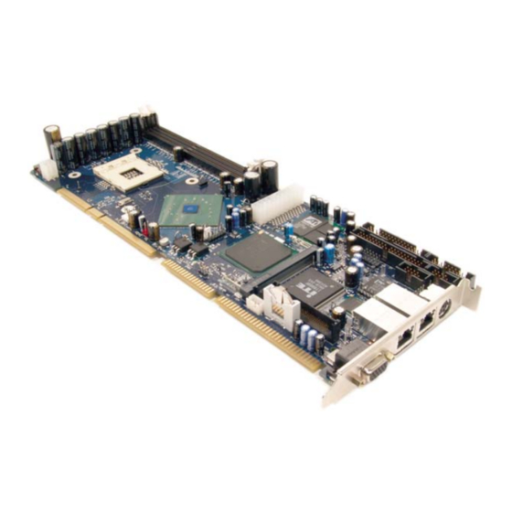
Page 32: Figure 1-1. Pci-953 Single Board Computer
10/100/1Gb Ethernet Compact Flash Battery MiniPCI Socket ATI Radeon M7 VGA Controller Intel 6300ESB I/O Controller Hub (ICH) 64-bit PCI Support DDR Memory Intel 82875P Memory Controller Hub (MCH) Figure 1-1. PCI-953 Single Board Computer PCI-953 Single Board Computer User’s Guide... -
Page 33: Checklist
PCI-953 Quick Reference Kontron Driver CD with drivers for all integrated components (supporting Windows 2000/XP). If any of these items is damaged or missing, please contact Kontron. Save all packing materials for future replacement and maintenance. Overview PCI-953 Single Board Computer User’s Guide... -
Page 34: Product Specifications
HDD LED interface, and I Real-Time Clock (RTC): Motorola MC146818A-compatible RTC provides 256 bytes of battery backup for 7 year data retention Watchdog Timer: Programmable timeout intervals from 1us - 1s or 10ms- 10min PCI-953 Single Board Computer User’s Guide... - Page 35 Dimension (L X W): 13.3 X 4.8 in (330 X 121.8mm) Operating Temperature: 5 C to 50 C (41 F to 122 Storage Temperature: -10 C to 60 C (14 F to 140 Relative Humidity: 20% to 80%, non-condensing Product Specifications PCI-953 Single Board Computer User’s Guide...
-
Page 36: System Architecture
The Super I/O chip LPC47B27X integrates two high speed serial ports, a FDD interface, and an 8042 keyboard controller with a PS/2 mouse port. In addition, an advanced feature is used on the PCI-953 single board computer to support detection and monitoring of the system temperature, operating voltage, and fan status. -
Page 37: System Block Diagram
Bus A - PCI -64/66; 528MB/s - 4lds 528MB/s Progrmble 2 x USB 2.0 Hdr Logic H/W Monitor USB Bus K/B & Mse Hdr LPC Bus Firmware Hub Super I/O PS2 KB/ W83627HF Mouse Optional Floppy Conn Item System Block Diagram PCI-953 Single Board Computer User’s Guide... - Page 38 This page intentionally left blank.
-
Page 39: Hardware Settings
Chapter 2 Hardware Settings Contents Overview ..........2-3 Jumpers . -
Page 41: Overview
This chapter provides the definitions and locations of jumpers, headers, and connectors. The PCI-953 is a jumperless board, which is controlled by the BIOS settings. It is not necessary to configure any jumpers for this board unless you intend to clear CMOS memory. CMOS Settings on the PCI-953 single board computer are shipped with the default settings. -
Page 42: Figure 2-2. Jumper Locations
Clear CMOS (J40) Figure 2-2. Jumper Locations PCI-953 Single Board Computer User’s Guide... -
Page 43: Clear Cmos Operation
4) Reconnect the system power and turn on the system. The message “CMOS settings wrong” and “ CMOS date/time not set” will be displayed and the system will hold up. Follow the displayed messages to reload the BIOS default settings. Jumpers PCI-953 Single Board Computer User’s Guide... -
Page 44: Connectors
MiniPCI Socket (J24) (J7) USB3/4 (J13) LCD Panel Header (J10) Chassis Fan (J27) ATX Power Input (J12) CPU Fan (J38) DIMM Slots ATX-12V Power Input (J42) * Refer to Figure 2-4 for pin numbering assignments. PCI-953 Single Board Computer User’s Guide... -
Page 45: Figure 2-3. Connector Locations
LAN1/LAN2 Dual 10/100/1GB Ethernet Ports 1-2 Dual RJ-45 with 4 LEDs Fixed rear panel VGA connector HBD-15 connector USB3/ USB4 – Dual USB Interface 10-pin unshrouded header DIMM 1-2 DIMM socket 2.5V DDR-400 Connectors PCI-953 Single Board Computer User’s Guide... -
Page 46: Connector Pin Assignments
Connector Pin Assignments J4: Floppy Connector Signal Signal DENSEL DRATE0 INDEX# MTR0# DRVS1# DRVS0# MRT1# DIR# STEP# WDATA# WGATE# TRK0# WRPRT# RDATA# HDSEL# DSKCHG# PCI-953 Single Board Computer User’s Guide... -
Page 47: Figure 2-4. System Interface Connector - Pin Assignments
Speaker (1, 2) I2C Bus (3,4) Chassis Intrusion Alarm (9, 10) Power Button (13, 14) Reset Button (15, 16) Power Indicator LED(17, 18) IDE LED (19, 20) Figure 2-4. System Interface Connector – Pin Assignments Connectors PCI-953 Single Board Computer User’s Guide... - Page 48 Data 13 Data 1 Data 14 Data 0 Data 15 Ground Removed DMA REQ Ground IOW# Ground IOR# Ground IOCHRDY Pull-down DMA ACK# Ground INT REQ HDC CS0# HDC CS1# ADD Active# Ground PCI-953 Single Board Computer User’s Guide 2-10...
- Page 49 J10: LVDS LCD Panel Header Signal Signal TXOUT_L0- TXOUT_L0+ TXOUT_L1- TXOUT_L1+ TXOUT_L2- TXOUT_L2+ GND# TXOUT_L3- TXOUT_L3+ TXCLK_L- TXCLK_L+ TXOUT_U0- TXOUT_U0+ TXOUT_U1- TXOUT_U1+ TXOUT_U2- TXOUT_U2+ TXOUT_U3- TXOUT_U3+ TXCLK_U- TXCLK_U+ Connectors 2-11 PCI-953 Single Board Computer User’s Guide...
- Page 50 Signal Signal Data Carrier Detect (DCD) Data Set Ready (DSR) Receive Data (RXD) Request to Send (RTS) Transmit Data (TXD) Clear to Send (CTS) Data Terminal Ready (DTR) Ring Indicator (RI) Ground (GND) PCI-953 Single Board Computer User’s Guide 2-12...
- Page 51 J12: ATX Power Input Signal Signal +3.3V +3.3V +3.3V -12V PS_ON# PWR OK +5VSBY +12V J17: PS/2 Alternate Header Signal Keyboard Clock Ground Keyboard Data +5V (fused) Mouse Clock Mouse Data Connectors 2-13 PCI-953 Single Board Computer User’s Guide...
- Page 52 J18: PS/2 Keyboard/Mouse Combo Signal Keyboard Data Mouse Data +5V (fused) Keyboard Clock Mouse Clock J20/J25: USB1/USB2 Interfaces Signal DATA - DATA + Shield J27: Chassis Fan Signal FAN_status (pull-up 5V) PCI-953 Single Board Computer User’s Guide 2-14...
- Page 53 +3.3V REQ# GNT# +3.3V AD31 PME# AD29 Reserved AD30 AD27 +3.3V AD25 AD28 Reserved AD26 CBE3# AD24 AD23 IDSEL AD21 AD22 AD19 AD20 AD17 AD18 CEB2# AD16 IRDY# +3.3V FRAME# CLKRUN# TRDY# Connectors 2-15 PCI-953 Single Board Computer User’s Guide...
- Page 54 AD14 AD15 AD13 AD12 AD11 AD10 CBE0# +3.3V +3.3V Reserved Reserved Reserved AC_SYCN M66EN AC_SDATA_INA AC_SDATA_OUT AC_BIT_CLK AC_SDATA_INB AC_PRIMARY# AC_RST# MOD_AUDIO_OUT Reserved AUDIO_GND SYS_AUDIO_OUT SYS_AUDIO_IN SYS_AUDIO_OUT_GND SYS_AUDIO_IN_GND AUDIO_GND AUDIO_GND Reserved MPCIACT# VCC5A 3.3VAUX PCI-953 Single Board Computer User’s Guide 2-16...
- Page 55 J32/J33 : Serial ATA Connectors Signal J34: CompactFlash (Secondary IDE) Signal Signal Pull-up Data3 Data11 Data4 Data12 Data5 Data13 Data6 Data14 Data7 Data15 CS0# CS1# IOR# IOW# +3.3V Connectors 2-17 PCI-953 Single Board Computer User’s Guide...
- Page 56 J34: CompactFlash (Secondary IDE) Signal Signal +3.3V +3.3V CF_BOOT_EN# RST# IORDY +3.3V CF_ACT# Data0 Data1 Data8 Data2 Data9 Pull-down Data10 Pull-up J37: CPU Fan Signal FAN_status (pull-up 5V) PCI-953 Single Board Computer User’s Guide 2-18...
- Page 57 LAN1/LAN2: 10/100/1Gb Ethernet Ports 1-2 Signal TRP1+ TRP1- TRP2+ TRP3+ TRP3- TRP2- TRP4+ TRP4- USB 3/ USB 4: Dual USB Interface Signal Signal Shield DATA [0]- DATA [0]+ DATA [1]+ DATA [1]- Shield Connectors 2-19 PCI-953 Single Board Computer User’s Guide...
- Page 58 VGA: VGA Connector (hard-mounted to rear I/O) Signal +5V (fused) DDCDAT HSYNC VSYNC DDCCLK PCI-953 Single Board Computer User’s Guide 2-20...
-
Page 59: Table 2-2. Isa (8-Bit) Bus Pin Assignments
+12 Volts I/OCHRDY Ground SMEMW# SA19 SMEMR# SA18 IOW# SA17 IOR# SA16 DACK3# SA15 DRQ3 SA14 DACK1# SA13 DRQ1 SA12 REFRESH# SA11 SA10 IRQ7 IRQ6 IRQ5 IRQ4 IRQ3 DACK2# BALE +5Volts Ground Connectors 2-21 PCI-953 Single Board Computer User’s Guide... -
Page 60: Table 2-3. Isa (16-Bit) Bus Pin Assignments
I/OCS16# LA22 IRQ10 LA21 IRQ11 LA20 IRQ12 LA19 IRQ15 LA18 IRQ14 LA17 DACK0# MEMR# DRQ0# MEMW# DACK5# SD08 DRQ5 SD09 DACK6# SD10 DRQ6# SD11 DACK7# SD12 DRQ7 SD13 5VDC SD14 MASTER# SD15 GROUND PCI-953 Single Board Computer User’s Guide 2-22... -
Page 61: Table 2-4. Pci (32-Bit) Bus Pin Assignments
AD11 AD12 GNT# AD10 REQ# RESERVED AD30 AD31 +3.3V C/BE0# AD29 AD28 +3.3V AD26 AD27 +3.3V GNDA24 AD25 AD24 +3.3V IDSEL C/BE3# +3.3V AD23 AD22 AD20 REQ64# AD21 ACK64# AD19 AD18 +3.3V Connectors 2-23 PCI-953 Single Board Computer User’s Guide... -
Page 62: Table 2-5. Pci (64-Bit) Bus Pin Assignments
AD60 AD58 AD59 AD57 AD56 AD54 AD55 AD53 AD52 AD50 AD51 AD49 AD48 AD46 AD47 AD45 AD44 AD42 AD43 AD41 AD40 AD38 AD39 AD37 AD36 AD34 AD35 AD33 AD32 Reserved Reserved Reserved Reserved PCI-953 Single Board Computer User’s Guide 2-24... -
Page 63: System Installation
Chapter 3 System Installation Contents Overview ..........3-3 Pentium 4 Processor. -
Page 65: Overview
Overview This chapter describes how to set up your system, add processors and memory, and install the PCI-953 single board computer into a chassis. Pentium 4 Processor Installing a CPU 1) Lift the CPU socket lever on the borad outwards and upwards (Figure 3-1). -
Page 66: Figure 3-2. Heatsink Installation
5) Lay the board flat on a table and place the heatsink on top of the CPU. Apply slight down-pressure on the heatsink, while moving it back-and-forth (clockwise to counter- clockwise) to enhance thermal contact between the CPU and the heatsink. PCI-953 Single Board Computer User’s Guide... -
Page 67: Pentium 4 Processor
(Figure 3-2). Perform this step on both sides of the heatsink. Thumb tabs Retention Clip Fan Bracket Heatsink Figure 3-3. Heatsink Diagram Pentium 4 Processor PCI-953 Single Board Computer User’s Guide... -
Page 68: Main Memory
ECC, and non-ECC DDR modules up to 1GB per socket, 2GB total. The maximum memory size for 2.5V DDR-400 SDRAM is 1GB per socket, 2GB total unbuffered. Different size DRAM modules may be used. The PCI-953 single board computer will automatically detect the memory clock, based on the processor and SDRAM used. -
Page 69: Figure 3-4. Dimm Installation
The module release levers will return to their upright position when the DIMM card is completely seated in the socket. The pegs on the tips of the release levers should align with the notches on both ends of the DIMM card. Main Memory PCI-953 Single Board Computer User’s Guide... -
Page 70: Installation
Installation To install the PCI-953 single board computer into a chassis, perform the following steps: 1) Install the processor and memory modules (Figure 3-1 and Figure 3-4). 2) Make sure that a PICMG-1.0 backplane is properly secured in the desired chassis. -
Page 71: Inf Chipset Component Driver
In a windows environment, the ATI Radeon M7 video driver appears as “ATI M7” in the /Video directory of the Kontron CPU Board Driver CD. On-board LED Indicator (for LAN status) The PCI-953 single board computer provides two LED indicators to show the status of the gigabit ethernet interfaces. Installation... - Page 72 This page intentionally left blank,...
-
Page 73: Bios Setup
Chapter 4 BIOS Setup Contents Overview ..........4-3 Main Menu . -
Page 75: Overview
Overview The PCI-953 single board computer is equipped with the AMI BIOS, which is stored in Flash ROM. This AMI BIOS features a built-in setup program, allowing users to modify the system configuration. The system configuration is stored in CMOS RAM so it is retained during power-off periods. -
Page 76: Figure 4-1. Main Menu - Screen Shot
Press <DEL> to enter SETUP Pressing [DEL] displays the Main Menu, which looks like this: Figure 4-1. Main Menu – Screen Shot See page 4 - 7 for a description of the fields on this menu. PCI-953 Single Board Computer User’s Guide... -
Page 77: The Menu Bar
Exits the system setup and saves settings to CMOS. Use the left and right arrow keys to make a selection. See the section below, "Exiting Setup," for a description on exiting the Main Menu. Main Menu PCI-953 Single Board Computer User’s Guide... -
Page 78: Table 4-1. Bios Setup Navigation Keys
To display a sub menu, use the arrow keys to move the cursor to the sub menu you want. Then press [Enter]. A pointer ( ) marks all sub menus. PCI-953 Single Board Computer User’s Guide... -
Page 79: Figure 4-2. General Help Menu
System Time This allows you to change the system time stored in the AMI BIOS. System Date This allows you to change the system date stored in the AMI BIOS. Main Menu PCI-953 Single Board Computer User’s Guide... -
Page 80: Figure 4-3. Advanced Menu
Advanced Menu Selecting "Advanced" from the menu bar on the Main Menu displays a menu like this: Figure 4-3. Advanced Menu PCI-953 Single Board Computer User’s Guide... - Page 81 This menu configures remote access via serial Configuration connection. USB Configuration This menu Enables or Disables USB support for legacy products. Gigabit Ethernet This menu configures the gigabit ethernet Configuration controllers and PXE support. Advanced Menu PCI-953 Single Board Computer User’s Guide...
-
Page 82: Figure 4-4. Cpu Configuration Menu
This selection displays the type of processor used in the system. Frequency This selection displays the processor frequency. FSB Speed This selection detects the system front side bus. Cache L1 and L2 These options display the L1 and L2 cache allocated. PCI-953 Single Board Computer User’s Guide 4-10... - Page 83 This option enabled hyper threading technology in the CPU. The Optimal setting is Enabled. The fail-safe setting is Disabled. Disabled Set this value to disable hyper threading processor support. Enabled* Set this value to enable hyper threading processor support. This is the default setting. Advanced Menu 4-11 PCI-953 Single Board Computer User’s Guide...
-
Page 84: Figure 4-5. Ide Configuration Control Menu
This function specifies the performance of S-ATA channels. Yes* Set this value to enable S-ATA enhanced mode. This is the optimal and fail-safe default setting. Set this value to allow the BIOS to boot legacy operating systems. PCI-953 Single Board Computer User’s Guide 4-12... - Page 85 Set this value to Yes to configure S-ATA devices for RAID. S-ATA 2nd Channel Set this value to No to utilize S-ATA devices without RAID. This is the optimal and fail-safe default setting. Advanced Menu 4-13 PCI-953 Single Board Computer User’s Guide...
- Page 86 Set this option to stop the BIOS from searching the IDE bus for IDE devices in thirty seconds. This is the default setting and is recommended for all IDE devices that are set to AUTO in the BIOS setting. PCI-953 Single Board Computer User’s Guide 4-14...
- Page 87 Set this value to use the CPU board to detect the type of IDE cable present. Device Set this value to use the IDE device to detect the type of IDE cable present. Advanced Menu 4-15 PCI-953 Single Board Computer User’s Guide...
- Page 88 Each P-ATA interface supports one master drive and one optional slave drive. Each S- ATA interface supports one master drive. The PCI-953 has one IDE connector which is the primary IDE interface. The secondary IDE interface is connected to the Compact Flash connector, which only supports a single drive, either master or slave.
-
Page 89: Figure 4-6. Disk Drive Settings
Use the legend keys listed on the bottom to make your selections and exit to the IDE Configuration Menu. Use the following chart to configure the hard disk. Drive Parameters Parameter Description Device Type of device Vendor Manufacturer of the device Size The size of the device Advanced Menu 4-17 PCI-953 Single Board Computer User’s Guide... - Page 90 Note: Exiting this menu keeps your selections but loses internal autotyping information, which may not be selected. If you exit this menu and re-enter it, press [Enter] on Autotype again to restore the Autotype information. PCI-953 Single Board Computer User’s Guide 4-18...
- Page 91 This option indicates that an IDE CD-ROM drive is attached to the specified channel. The BIOS will not search for additional IDE drives on this channel. ARMD This options specifies an ATAPI removable media device, such as: LS-120 Advanced Menu 4-19 PCI-953 Single Board Computer User’s Guide...
- Page 92 Set this value to allow the BIOS to use PIO mode 1. It has a data transfer rate of 5.2 MBs. Set this value to allow the BIOS to use PIO mode 2. It has a data transfer rate of 8.3 MBs. PCI-953 Single Board Computer User’s Guide 4-20...
- Page 93 Set this value to allow the BIOS to use Ultra DMA mode 1. It has a data transfer rate of 25 MBs. UDMA2 Set this value to allow the BIOS to use Ultra DMA mode 2. It has a data transfer rate of 33.3 MBs. Advanced Menu 4-21 PCI-953 Single Board Computer User’s Guide...
- Page 94 Set this value to prevent the BIOS from using 32-bit data transfers. Enabled* Set this value to allow the BIOS to use 32-bit data transfers on support hard disk drives. This is the default setting. PCI-953 Single Board Computer User’s Guide 4-22...
-
Page 95: Figure 4-7. Floppy Configuration Menu
Set this value for ARMD to emulate a floppy drive during boot up. Hard Disk Set this value for ARMD to emulate a hard disk drive during boot up. Floppy Configuration Figure 4-7. Floppy Configuration Menu Advanced Menu 4-23 PCI-953 Single Board Computer User’s Guide... - Page 96 This is the default setting. Enabled Set this value to allow the BIOS to seek the floppy disk drive during boot up. This will cause the floppy disk drive to temporarily power on during POST. PCI-953 Single Board Computer User’s Guide 4-24...
-
Page 97: Figure 4-8. Super Io Configuration Menu
This function enables or disables the floppy drive controller. Disabled Set this value to disable the floppy drive controller. Enabled* Set this value to enable the floppy drive controller. This is the default setting. Advanced Menu 4-25 PCI-953 Single Board Computer User’s Guide... - Page 98 Set this value to allow the serial port to use 3F8 as its I/O port address and IRQ 4 for the interrupt address. If the system will not use a serial device, it is best to set this port to Disabled. PCI-953 Single Board Computer User’s Guide 4-26...
- Page 99 Set this value to allow the serial port to use 2E8 as its I/O port address and IRQ 3 for the interrupt address. If the system will not use a serial device, it is best to set this port to Disabled. Advanced Menu 4-27 PCI-953 Single Board Computer User’s Guide...
-
Page 100: Figure 4-9. Hardware Health Configuration Menu
This function enables system health monitoring. Disabled Set this value to disable the hardware health function. Enabled* Set this value to monitor the system’s health status. This is the optimal and fail-safe default setting. PCI-953 Single Board Computer User’s Guide 4-28... -
Page 101: Figure 4-10. Acpi Setup Menu
ACPI Setup Selecting ‘ACPI’ from the Main menu in the BIOS utility will open the following screen: Figure 4-10. ACPI Setup Menu Advanced Menu 4-29 PCI-953 Single Board Computer User’s Guide... -
Page 102: Figure 4-11. General Acpi Configuration Menu
Options: No*, Yes USB Device Wakeup from S3/S4 This option determines if a USB device may wake the system from an S3/S4 suspend state. Disabled is the optimal and fail-safe default setting. Options: Disabled*, Enabled PCI-953 Single Board Computer User’s Guide 4-30... -
Page 103: Figure 4-12. Acpi Advanced Menu
This option determines whether or not to include the ACPI APIC table pointer to the RSDT pointer list. Enabled is the optimal and fail-safe default setting. Enabled* This setting will initiate ACPI APIC support .This is the default setting. Disabled This setting disables ACPI APIC support. Advanced Menu 4-31 PCI-953 Single Board Computer User’s Guide... - Page 104 ACPI Machine Language (AML) is a binary code format that the operating system's ACPI AML interpreter parses to discover the machine's properties. On boot up the BIOS startup code copies it into system memory, where it can be interpreted by the operating system’s ACPI AML interpreter. PCI-953 Single Board Computer User’s Guide 4-32...
- Page 105 This option is used to update the ACPI FACP table to indicate headless operations. Disabled This option disables updating the ACPI FACP table to indicate headless operation. Enabled This option enables updating the ACPI FACP table to indicate headless operation. Advanced Menu 4-33 PCI-953 Single Board Computer User’s Guide...
-
Page 106: Figure 4-13. Event Log Configuration Menu
Clear Event Log This selection allows you to clear all events in the event log. Event Log Statistics This selection displays the total space, used space, and free space in the event log. PCI-953 Single Board Computer User’s Guide 4-34... -
Page 107: Figure 4-14. Isa Bridge Configuration Menu
Enabled Set this value to enable PCI Error Logging. ISA Bridge Configuration This menu allows you to configure the ITE8888 PCI to ISA bridge. Figure 4-14. ISA Bridge Configuration Menu Advanced Menu 4-35 PCI-953 Single Board Computer User’s Guide... - Page 108 Options: 3.5 BCLK*, 5.5 BCLK, 7.5, BCLK, 11.5 BCLK. MPS Configuration Use this screen to configure the Multi-processor specification. MPS Revision This selects the appropriate MPS revision to use in creating the multi-processor table. PCI-953 Single Board Computer User’s Guide 4-36...
-
Page 109: Figure 4-15. Remote Access Configuration Menu
Set this value to prevent the BIOS from using Remote Access. Serial Set the value for this option to Serial to allow the system to use the remote access feature. The remote access feature requires a dedicated serial port connection. Advanced Menu 4-37 PCI-953 Single Board Computer User’s Guide... - Page 110 Set this value to allow you to select 57600 as the baud rate (transmitted bits per second) of the serial port. 19200 8,n,1 Set this value to allow you to select 19200 as the baud rate (transmitted bits per second) of the serial port. PCI-953 Single Board Computer User’s Guide 4-38...
-
Page 111: Figure 4-16. Usb Configuration Menu
This setting makes the onboard USB ports unavailable. 2 USB Ports This setting enables 2 USB ports. All USB Ports* This setting enables all USB ports. This is the default setting. Advanced Menu 4-39 PCI-953 Single Board Computer User’s Guide... - Page 112 Speed mode (480Mbps). This is the optimal default setting. Full Speed Set this value to configure the USB 2.0 controller to operate in Full Speed mode (12Mbps). This is the fail-safe default setting. PCI-953 Single Board Computer User’s Guide 4-40...
-
Page 113: Figure 4-17. Gigabit Ethernet Configuration Menu
This is the default setting. PXE Boot to LAN This option enables/disables the PXE option ROM for the Intel 82547 gigabit ethernet controller. Disabled is the optimal and fail-safe default setting. Options: Disabled*, Enabled Advanced Menu 4-41 PCI-953 Single Board Computer User’s Guide... - Page 114 This is the default setting. PXE Boot to LAN This option enables/disables the PXE option ROM for the Intel 82540 gigabit ethernet controller. Disabled is the optimal and fail-safe default setting. Options: Disabled*, Enabled PCI-953 Single Board Computer User’s Guide 4-42...
-
Page 115: Figure 4-18. Pci/Pnp Setup Menu
This is the default setting. The Yes setting allows the operating system to change the interrupt, I/ O, and DMA settings. Set this option if the system is running Plug and Play aware operating systems. PCI/PnP Setup 4-43 PCI-953 Single Board Computer User’s Guide... - Page 116 Set this value to allow the allocation of an IRQ to a VGA adapter card that uses the PCI local bus. This is the default setting. Set this value to prevent the allocation of an IRQ to a VGA adapter card that uses the PCI local bus. PCI-953 Single Board Computer User’s Guide 4-44...
- Page 117 This setting will select PCI Slot 2 as the location of the OffBoard PCI IDE adapter card. Use this setting only if there is an IDE adapter card installed in PCI Slot 2. PCI/PnP Setup 4-45 PCI-953 Single Board Computer User’s Guide...
- Page 118 This setting allows the specified IRQ to be used by a PCI/ IRQ4 PnP device. IRQ5 IRQ7 IRQ9 IRQ10 Reserved This setting allows the specified IRQ to be used by a legacy IRQ11 ISA device. IRQ14 IRQ15 PCI-953 Single Board Computer User’s Guide 4-46...
- Page 119 Set this value to allow the system to reserve 32K of the system memory to the ISA devices. Set this value to allow the system to reserve 64K of the system memory to the ISA devices. PCI/PnP Setup 4-47 PCI-953 Single Board Computer User’s Guide...
- Page 120 Set ISA memory base to CC000h. D0000 Set ISA memory base to D0000h. D4000 Set ISA memory base to D4000h. D8000 Set ISA memory base to D8000h. DC000 Set ISA memory base to DC000h. PCI-953 Single Board Computer User’s Guide 4-48...
-
Page 121: Figure 4-19. Boot Menu
Operating System. In the example above, the BIOS will attempt first to boot from the floppy drive. Failing that, it will attempt to boot from the CD-ROM driver, and then the Primary Master hard disk, and so on down the list. Boot Menu 4-49 PCI-953 Single Board Computer User’s Guide... -
Page 122: Figure 4-20. Boot Settings Configuration Menu
Devices and Hard Drive. Pressing [Shift+1] enables or disables a device. To access the properties or boot features of each boot device, select the device using the up-or-down arrows and press [Enter] (Figure 4-19). Boot Settings Configuration Figure 4-20. Boot Settings Configuration Menu PCI-953 Single Board Computer User’s Guide 4-50... - Page 123 Set this value to allow the computer system to force a third party BIOS to display during system boot. This is the default setting. Keep Current Set this value to allow the computer system to display the ezPORT information during system boot. Boot Menu 4-51 PCI-953 Single Board Computer User’s Guide...
- Page 124 Use this setting if installing a serial mouse. Enabled* Set this value to allow the system to use a PS/2 mouse. This is the default setting. PCI-953 Single Board Computer User’s Guide 4-52...
- Page 125 When enabled, this function allows option ROMs to trap INT 19h. Disabled* Set this value to disable this function. This is the default setting. Enabled Set this value to allow the system to trap INT19h. Boot Menu 4-53 PCI-953 Single Board Computer User’s Guide...
- Page 126 Note: When you select a boot category from the boot menu, a list of devices in that category appears. For example, if the system has three hard disk drives connected, then the list will show all three hard disk drives attached. PCI-953 Single Board Computer User’s Guide 4-54...
- Page 127 Hard Disk Drives Selecting ‘Hard Disk Drives’ from the Boot menu in the BIOS utility will open the Hard Disk Drives screen. Boot Menu 4-55 PCI-953 Single Board Computer User’s Guide...
- Page 128 Removable Devices Selecting ‘Removable Devices’ from the Boot menu in the BIOS utility will open the Removable Devices screen. PCI-953 Single Board Computer User’s Guide 4-56...
- Page 129 Set this value to allow option ROMs such as network controllers to trap BIOS interrupt 19. Disabled The BIOS prevents option ROMs from trapping interrupt 19. Enabled The BIOS allows option ROMs to trap interrupt 19. Boot Menu 4-57 PCI-953 Single Board Computer User’s Guide...
-
Page 130: Security Setup
<Enter>: Change Supervisor Password Change User Password Clear User Password The Security Setup screen is shown below. The sub menus are documented on the following pages. PCI-953 Single Board Computer User’s Guide 4-58... -
Page 131: Figure 4-21. Security Setup Menu
Select this option and press <Enter> to access the sub menu. You can use the sub menu to change the supervisor password. Change User Password Select this option and press <Enter> to access the sub menu. You can use the sub menu to change the user password. Security Setup 4-59 PCI-953 Single Board Computer User’s Guide... - Page 132 Type the password and press <Enter>. The screen does not display the characters entered. Retype the password as prompted and press <Enter>. If the password confirmation is incorrect, an error message appears. The password is stored in NVRAM after ezPORT completes. PCI-953 Single Board Computer User’s Guide 4-60...
- Page 133 Type the password and press <Enter>. The screen does not display the characters entered. Retype the password as prompted and press <Enter>. If the password confirmation is incorrect, an error message appears. The password is stored in NVRAM when completed. Security Setup 4-61 PCI-953 Single Board Computer User’s Guide...
-
Page 134: Figure 4-22. Chipset Setup Menu
This value selects a DRAM frequency of 333MHz. This value selects a DRAM frequency of 400MHz. Auto* This value automatically selects the correct DRAM frequency. This is the optimal default setting. PCI-953 Single Board Computer User’s Guide 4-62... - Page 135 This option selects the DRAM precharge delay. 8CLKs is the optimal and fail-safe default setting. Options: 5CLKs, 6CLKs, 7CLKs, 8CLKs* DRAM Burst Length This option selects the DRAM burst length. 8 is the optimal default setting. 4 is the fail-safe default setting. Options: 4, 8* Chipset Setup 4-63 PCI-953 Single Board Computer User’s Guide...
- Page 136 Options: AGP, PCI* Graphics Aperture Size This option selects the size of the AGP aperture. 64MB is the optimal and fail-safe default setting. Options: 4MB, 8MB, 16MB, 32MB, 64MB*, 128MB, 256MB PCI-953 Single Board Computer User’s Guide 4-64...
-
Page 137: Figure 4-23. Power Setup Menu
Figure 4-23. Power Setup Menu Note: The Power Management Setup screen is not displayed when Advanced Power Management (APM) is not supported. The Power Setup screen can vary for different motherboards. Power Setup 4-65 PCI-953 Single Board Computer User’s Guide... - Page 138 This means the monitor is not off. The screen will appear blacked out. The standards do not cite specific power ratings because they vary from monitor to monitor, but this setting use less power than Standby mode. PCI-953 Single Board Computer User’s Guide 4-66...
- Page 139 Set this value to allow the computer system to enter standby mode after being inactive for 50min. 60min Set this value to allow the computer system to enter standby mode after being inactive for 60min. Power Setup 4-67 PCI-953 Single Board Computer User’s Guide...
- Page 140 Power management will monitor activity on these devices to determine activity occurring in the system. Monitor is the optimal and fail-safe default setting. Ignore This selection ignores activity on this device. Monitor* This selection monitors activity on this device. PCI-953 Single Board Computer User’s Guide 4-68...
- Page 141 Power management will monitor activity on these devices to determine activity occurring in the system. Monitor is the optimal and fail-safe default setting. Ignore This selection ignores activity on this device. Monitor* This selection monitors activity on this device. Power Setup 4-69 PCI-953 Single Board Computer User’s Guide...
- Page 142 This setting allows the BIOS to throttle back the CPU clock to operate 25 percent of the time. 12.5% This setting allows the BIOS to throttle back the CPU clock to operate 12.5 percent of the time. PCI-953 Single Board Computer User’s Guide 4-70...
- Page 143 This selection restores the system power and turns the system on after AC power is restored. Last State* This selection returns to the previous powered state when AC power is restored. This is the default setting. PCI-953 Single Board Computer User’s Guide 4-71...
- Page 144 (PME) is generated by the system. Set this value to enable/disable the Resume on PME# wake event. Disabled* This setting disables the Resume on PME# wake event. This is the default setting. PCI-953 Single Board Computer User’s Guide 4-72...
- Page 145 (RTC) alarm to specify a wake up time. Set this value to enable/disable the Resume on RTC Alarm wake event. Disabled* This setting disables the Resume on RTC Alarm wake event. This is the default setting. Enabled This setting enables the Resume on RTC Alarm wake event. Power Setup 4-73 PCI-953 Single Board Computer User’s Guide...
-
Page 146: Figure 4-24. Exit Menu
The next time you boot your computer, the BIOS configures your system according to the Setup selections stored in CMOS. After you save your selections, the program prompts with this message: Save configuration changes and exit now? [Yes] [No] PCI-953 Single Board Computer User’s Guide 4-74... - Page 147 Make your selection using the arrow keys and press Enter. If the BIOS program detects a problem in the integrity of values stored in CMOS during boot up, it displays these messages: System CMOS checksum bad - run SETUP Press <F1> to resume, <F2> to Setup Exit Menu 4-75 PCI-953 Single Board Computer User’s Guide...
- Page 148 You can make other changes before saving the values to CMOS. Save Changes Selecting “Save Changes” saves all the selections without exiting Setup. You can return to the other menus if you want to review and change your selections. PCI-953 Single Board Computer User’s Guide 4-76...
- Page 149 Chapter 5 Troubleshooting Contents On-board Hardware Installation ....... 5-3 BIOS Setting..........5-4 Operating System (OS) Diagnostics .
-
Page 151: On-Board Hardware Installation
Users may install a PS/2 keyboard and mouse with a PS/2 mouse? interface (using a Y-cable), J18, on the I/O board bracket of the PCI-953. By default, a PS/2 keyboard will work if no Y-cable is used. However, it is also fine to install a standard keyboard using the PS/2 alternate header (J17) or via the standard keyboard connector on the backplane, if available. -
Page 152: Bios Setting
It is possible to encounter system failures that result in malfunction of any device if these are not correctly installed. To make sure that you have a successful start with the PCI-953 single board computer, it is recommended, when going with the boot-up sequence, to press the [Del] key and enter the BIOS setup menu to create a BIOS configuration that matches your application requirements. - Page 153 2) Press [Enter] and “Y” to load in the default optimal BIOS setup. This will force your BIOS setting back to the initial factory configuration. Kontron recommends that you to do this any time the system appears to be unstable during the boot up sequence.
- Page 154 It is then very easy to find out which IRQ resource is available for additional peripherals. If the IRQ resource is not enough, disable some of the devices listed above to release additional IRQ resources. PCI-953 Single Board Computer User’s Guide...
-
Page 155: Operating System (Os) Diagnostics
Windows OS. You will then be able to see this NT hard disk and retrieve any data. However, if this NT hard disk is installed with NTFS disk format, only NTFS allow you to retrieve this hard disk data. Operating System (OS) Diagnostics PCI-953 Single Board Computer User’s Guide... -
Page 156: Display Setup
2) If you are using a monitor that Windows cannot identify, in the “Display Setup” menu select an appropriate monitor manually. 3) For Windows-NT 4.0 users, as PCI-953 provides Direct AGP on-board, Service Pack 3.0 or above is required to activate this display feature. - Page 157 Note: Network setup within Windows-NT 4.0 is not as easy as within Windows 95/98/ME. Special familiarity and care are required to come out with a successful installation. Contact Kontron Technical Support for assistance. Operating System (OS) Diagnostics PCI-953 Single Board Computer User’s Guide...
- Page 158 PCI-953 Single Board Computer User’s Guide 5-10...
Need help?
Do you have a question about the PCI-953 and is the answer not in the manual?
Questions and answers