Table of Contents
Advertisement
Available languages
Available languages
Quick Links
ANLEITUNG FÜR EINBAU, BEDIENUNG UND WARTUNG
KESSEL-Kleinkläranlagen INNO-CLEAN
- die vollbiologische Kleinkläranlage
zur Reinigung häuslichen Abwassers
nach EN 12566, Teil III
INNO-CLEAN
zum Einbau ins Erdreich
in den Nenngrößen
EW 4 bis EW 50
Installation
der Anlage wurde durchgeführt von Ihrem Fachbetrieb:
Name/Unterschrift
Stand 11/2009
+
-Kleinkläranlage
Inbetriebnahme
Datum
Produktvorteile
Geringe Energiekosten
Geringe Wartungs- und Instandhaltungs-
kosten
Hohe Standzeit
durch Behälter aus Kunststoff
Dauerhafte Dichtheit durch
monolithisch rotierten Behälter
Keine Schwefelkorrosion
Leichter Einbau durch geringes Gewicht
Hohe Bruchsicherheit durch PE
Reinigungsklassen C und D zugelassen
Einweisung
Ort
+
Anleitung kann über
www.kessel.de
im Format DIN A 4
heruntergeladen werden!
Bedienungsanleitung
Seite 1-43
Instructions de Montage
Page 44-86
Installation Manual
Page 87-132
Stempel Fachbetrieb
Sach-Nr. 010-430
Advertisement
Chapters
Table of Contents

Subscribe to Our Youtube Channel
Related Manuals for Kessel IINNO-CLEAN+


Summary of Contents for Kessel IINNO-CLEAN+
- Page 1 ANLEITUNG FÜR EINBAU, BEDIENUNG UND WARTUNG KESSEL-Kleinkläranlagen INNO-CLEAN Anleitung kann über - die vollbiologische Kleinkläranlage www.kessel.de im Format DIN A 4 zur Reinigung häuslichen Abwassers heruntergeladen werden! nach EN 12566, Teil III Bedienungsanleitung Seite 1-43 INNO-CLEAN -Kleinkläranlage Instructions de Montage...
- Page 2 1. Sicherheitshinweise Achtung! Erstickungsgefahr beim Betreten der Anlage Das Personal für Montage, Bedienung, Wartung und Reparatur muss die entsprechende Qualifikati- on für diese Arbeiten aufweisen. Der Verantwortungsbereich, die Zuständigkeit und die Überwachung des Personals müssen durch den Betreiber genau geregelt sein. Die Betriebssicherheit der gelieferten Anlage ist nur bei bestimmungsgemäßer Verwendung gewähr- leistet.
-
Page 3: Table Of Contents
Inhaltsverzeichnis ......................Seite 1. Sicherheitshinweise 2.1 Einsatzbereich ................ Seite 2.2 Anlagenbeschreibung .............. Seite 2. Allgemeines 2.3 Anlagenkonfiguration .............. Seite 2.4 Maße und Nutzvolumen ............Seite 2.5 Funktionsbeschreibung ............Seite 12 3.1 Verpackung................Seite 14 3.2 Transport ................. Seite 14 3. - Page 4 Sehr geehrter Kunde, wir freuen uns, dass Sie sich für ein Produkt von KESSEL entschieden haben. Die gesamte Anlage wurde vor Verlassen des Werkes einer strengen Qualitätskontrolle unterzogen. Prüfen Sie bitte den- noch sofort, ob die Anlage vollständig und unbeschädigt bei Ihnen angeliefert wurde. Im Falle eines Transportschadens beachten Sie bitte die Anweisungen in Kapitel „Gewährleistung“...
-
Page 5: Einsatzbereich
2.1 Einsatzbereich zung wird von einem Verdichter bereitgestellt und durch INNO-CLEAN , die Kleinkläranlage von KESSEL, ist eine eine Steuereinheit vollautomatisch geregelt. Der Verdichter Reinigungsanlage für häusliche Abwässer nach EN 12566, und die Steuerung sind zum freien Einbau in frostgeschütz- Teil III. -
Page 6: Anlagenkonfiguration
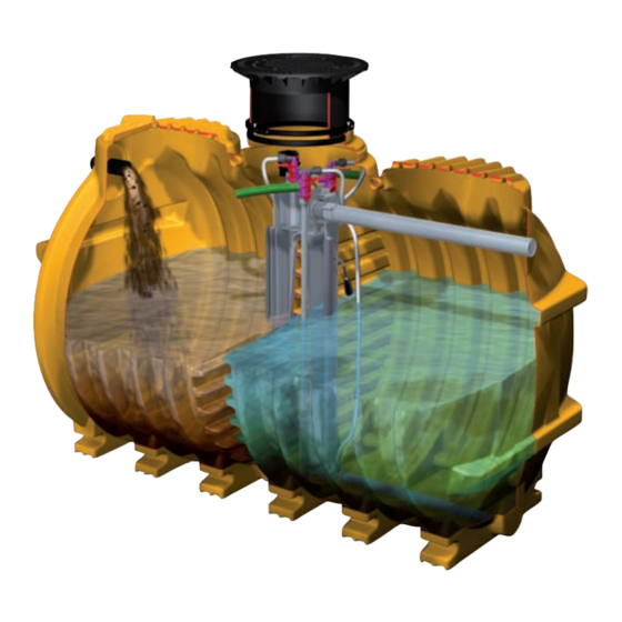
2. Allgemeines 2.3 Anlagenkonfiguration Seitenansicht Behälter EW 4 - 6 Nutzvolumen 4800 l Seitenansicht Behälter EW 8 -10 Nutzvolumen 7600 l Frontansicht... -
Page 7: Maße Und Nutzvolumen
2. Allgemeines 2.4 Maße und Nutzvolumen... - Page 8 2. Allgemeines Anlagenkonfiguration EW 4, EW 6, EW 8 und EW 10...
- Page 9 2. Allgemeines Anlagenkonfiguration EW 12, EW 14, EW 16 und EW 20...
- Page 10 2. Allgemeines Anlagenkonfiguration EW 22 bis EW 30...
- Page 11 2. Allgemeines Anlagenkonfiguration EW 32 bis EW 50...
-
Page 12: Funktionsbeschreibung
2. Allgemeines 2.5 Funktionsbeschreibung Der Klärprozess wird vollautomatisch von der Steuereinheit geregelt. Ein Klär- zyklus dauert ca. 8 Stunden und wird durch Abführen des geklärten Wassers beendet. Der Klärungsprozess basiert auf Mikro- organismen, die während der Behand- lungsphase das Abwasser reinigen. 1. - Page 13 2. Allgemeines 4. Absetzphase Nach der Behandlungsphase folgt eine zweistündige Absetzphase. Alle in dem Ab- wasser enthaltenen Feststoffe, sowie der Belebtschlamm setzen sich am Beckenbo- den ab somit bildet sich im oberen Bereich eine Klarwasserschicht und am Boden eine Schlammschicht aus Mikroorganismen. 5.
-
Page 14: Verpackung
3. Verpackung, Transport und Lagerung Das Kapitel Sicherheitshinweise ist zu beachten! Eine Verpackung der Behälter zum Zwecke des Transports • Die Behälter sind gegen unzulässige Lageveränderungen 3.1 Verpackung bzw. der Lagerung ist bei Beachtung der nachfolgenden während der Beförderung zu sichern. Durch die Art der Be- Punkte nicht notwendig. -
Page 15: Einbauort
4. Einbau und Montage Während der Zwischenlagerung der Kleinkläranlage sind zusätzliche Schläuche notwendig. sowie bis zum Abschluss der Einbauarbeiten, müssen 4.2 Baugrube an der Baustelle geeignete Sicherungsmaßnahmen ge- troffen werden, um Unfälle und Beschädigungen der Kleinkläranlage zu verhindern. Das Kapitel Sicherheitshinweise ist zu beachten. Œ... -
Page 16: Einsetzen
Für die Durchführung durch die Gebäudewand muss in einer Breite von mindestens 50 cm hergestellt wer- empfiehlt KESSEL auf handelsübliche Wanddurchführun- den. Die einzelnen Lagen des Verfüllmaterials sollten nicht gen zurück zu greifen (siehe Bild). Zur Abdichtung des Ka- höher als 30 cm sein. -
Page 17: Verlegung Der Verbindungsleitungen
Dom angeschlossen. Eine zusätzliche Lüftungslei- tung kann am Dom angeschlossen werden (siehe Abb. S. 5). Hierzu ist die entsprechende Bohrkrone und Rohrdurch- führungsdichtung von KESSEL zu verwenden . KESSEL emp- fiehlt die Verwendung eines Aktivkohlefilters zur Vermeidung von Geruchsbelästigung. -
Page 18: Befüllen
4. Einbau und Montage Die Dichtlippe soll auf der Innenseite des Ringes nach unten zeigen. Das teleskopische KESSEL-Aufsatzstück im unteren Be- durch das stufenlos höhenverstellbare und bis 5° neigbare reich mit Gleitmittel einfetten und in die Behälteröffnung ein- Aufsatzstück ausgeglichen werden. Die mitgelieferten Auf- stecken, in die gewünschte Position bringen und mittels... -
Page 19: Einbau Steuereinheit Und Verdichter
Schnee und Frost geschützt sein. Die angesaugte Umge- Allgemeine Hinweise bungsluft muss frei von entflammbaren oder aggressiven ACHTUNG: KESSEL empfiehlt, für die Ausführung von Gasen oder Dämpfen sein. elektrischen Anschlüssen, einen Fachbetrieb des Elek- Die Schlauchleitung ist so kurz und so gerade wie möglich trohandwerks zu beauftragen. - Page 20 4. Einbau und Montage Montage und Anschluß Die Wandkonsole ist mittels beider mitgelieferter Dübel und Schrauben waagerecht an der Wand zu fixieren. Das Steuergerät durch Lösen der vier stirnseitigen Kreuzschlitzschrauben öffnen und dessen Rückwand mit den mitgelieferten vier Kreuzschlitzschrauben an den vorgebohrten Stellen der Wandkonsole (unter- halb der Abstellfläche für den Verdichter) befestigen.
- Page 21 4. Einbau und Montage Optionale Anschlüsse am Schaltgerät: Achtung: Alle optionalen Anschlüsse sind nur durch Elektrofachkräfte durchzuführen.
-
Page 22: Anlage In Betriebsbereitschaft Setzen
Hinweis: Die Netzleitung muss mit einem FI-Schutzautomaten ausgerüstet sein. Das Kapitel Sicherheitshinweise ist zu beachten! (S.2) Systemstart Die Inbetriebnahme wird von einem Fachbetrieb oder einem Systemdiagnose KESSEL-Beauftragten durchgeführt (gegen Aufpreis). Folgende Personen sollten bei der Übergabe anwesend sein: - Abnahmeberechtigter des Bauherrn Sprache deutsch - Fachbetrieb französisch... -
Page 23: Pflichten Des Betreibers
5. Inbetriebnahme Bei der Erstinitialisierung der Anlage fragt das Steuer- 5.3. Einweisung des Kunden anhand der Einbauanlei- gerät nach vier Grundeinstellungen. Im Display des tung Steuergerätes erscheint die Frage nach - Einbau- und Bedienungsanleitung mit Kunde durchgehen - Bedienung der Anlage (Erklären und Beschreiben) 1. -
Page 24: Betrieb
6. Betrieb und Entsorgung 6.1 Betrieb • Nur die Vorklärung muss regelmäßig (ca. alle 12-24 Mo- Nach Inbetriebnahme der Anlage bildet sich nach 3-6 Mo- nate) durch ein Entsorgungsunternehmen entschlammt naten eine aktive Belebtschlammschicht mit Mikroorganis- werden! Nach Rücksprache mit den zuständigen Wasser- men in der Belebungskammer. -
Page 25: Was Nicht In Die Biol. Kleinkläranlage Gehört
6. Betrieb und Entsorgung Halbjährliche Kontrollen Wartung durch einen Fachbetrieb. Dabei sind die Vorgaben der zuständigen Behörden zu beachten. Bei einer Schlamm- höhe von 95 cm vom Behälterboden sind ca. 70 % der Aufnahmekapazität erreicht. 6.3 Was nicht in eine biologische Kleinkläranlage gehört Folgende Hinweise sollten Sie im eigenen Interesse beachten: Feste oder flüssige Stoffe, Was sie anrichten... -
Page 26: Entsorgung
6. Betrieb und Entsorgung 6.4 Entsorgung Durchführung der Entsorgung In der Vorklärkammer sammelt sich Klärschlamm an. Dieser Entleerungsintervalle: muss entsorgt werden. Soweit nicht anders bestimmt, gelten folgende Entlee- Zum Aus- und Einheben der Schachtabdeckung mitgelie- rungsintervalle des Klärschlamms (aus der Vorklärkammer): ferte Aushebeschlüssel verwenden. -
Page 27: Vorklärung Und Belebung
7. Wartung 7.1 Wartung Vorklärung + Belebung den. Anschließend setzen Sie den Heber wieder in die ent- sprechende Position und schließen ihn wieder korrekt an. Hinweis: Informieren Sie sich, wer in Ihrem Gebiet für die • Sollte es aufgrund eines unzureichenden Belüftungsbildes Wartung von Kleinkläranlagen zuständig ist. - Page 28 - Sind abnormale Geräusch oder Vibrationen zu vernehmen? die gesonderte Einbau- und Bedienungsanleitung beachten. - Ist die Temperatur des Verdichters normal oder evtl. zu Eine Ersatzteilliste erhalten Sie über den Kundendienst der hoch? KESSEL . - Zeigt das Netzkabel etwaige Schäden auf?
- Page 29 7. Wartung...
- Page 30 8. Steuerung der Kleinkläranlage 8. Bedienung des Schaltgerätes Display/Anzeigenfeld Bewegungstasten/Richtungstasten Bestätigungstaste/OK-Taste Zurücktaste/ESC-Taste Kontrolllampe für Betriebsbereitschaft Kontrolllampe für Störungsmeldung Netzabschlusskabel Netzanschlus für Verdichter Anschluss Druckluftsensor Anschlussmöglichkeiten für externen Signalgeber Anschluss für Ventilblock Anschlussbuchse für potentialfreien Kontakt Menüführung Alarmtaste kann der akustische Alarm quittiert werden. Die Menüführung des Schaltgerätes ist in die Systeminfo, Der Stand-by-Modus wird für mind.
- Page 31 8. Steuerung der Kleinkläranlage 8.1.System-Menü Informationen Systeminfo Uhrzeit: 00:00:00 Schwimmer 1: Ein / Aus Wartung TX: (Phase T1 bis T24) TX1: (Zeit: 00:00:00) Einstellungen Anzeige der Hierarchie-Ebene Uhrzeit Anzeige der aktivierten Schwimmer, sowie deren Position Anzeige der Phase Anzeige der aktuell abgelaufenen Zeit der jeweil. Phase Anzeige von Alarm/Fehlerinformationen 8.2.1 Betriebsstunden 8.2 Informationsmenü...
- Page 32 8. Steuerung der Kleinkläranlage dichter wird hierbei nicht eingeschaltet. 8.3.3 Wartungstermin Eingabe des nächsten Wartungstermins durch den Wartungspartner. 8.4.1 Parameter 8.4 Einstellungsmenü Änderung werkseitig hinterlegter Parameter. Parameter Hinweis: Jede Änderung wird mit Bestätigung der Systeminfo Informationen Parameterspeicher OK-Taste sofort übernommen. Zusätzlich gibt es beim Verlassen des Menüs die Möglichkeit, diese Datum / Uhrzeit Wartung...
- Page 33 9. Störungen und Abhilfemaßnahmen Behebung Mögliche Ursache Fehler Fehleranzeige Schaltgerät - Einstellung auf 150 cm - Niveau zu niedrig eingestellt Hochwasser Schwimmer 2+ - Überprüfung der Zulaufmengen - Zulaufmenge zu hoch Hochwasser Sensor der Anlage Wasserstand in der Belebungs- - Klarwasserheber defekt oder - Überprüfung der hydraulischen kammer hat max.
- Page 34 9. Störungen und Abhilfemaßnahmen Fehler Mögliche Ursache Behebung - Akku einsetzen Akkuspannung zu hoch - Akku nicht vorhanden - Kontaktfehler am Akku - Akku auf Polarität und Sitz prüfen - Schaltgerät tauschen - Relaiskontakt im Schaltgerät Relaisfehler “verklebt” - Die Anlage ist stromlos - Vorsicherung und/oder Auf dem Display der Steuerung FI-Schalter überprüfen...
- Page 35 9. Störungen und Abhilfemaßnahmen Fehler Mögliche Ursache Behebung - Ist beim Handbetrieb Klarwasser- - Magnetventil defekt. abzug kein deutliches Öffnungs- geräusch feststellbar, Service an- rufen. - Die Einleitungsstelle muss wieder - Es kommt zum Rückstau an der freigängig gemacht werden. Einleitungsstelle.
- Page 36 10. Gewährleistung 1. Ist eine Lieferung oder Leistung mangelhaft, so hat KESSEL §§ 377.378 HGB finden weiterhin Anwendung. nach Ihrer Wahl den Mangel durch Nachbesserung zu beseiti- Über die gesetzliche Regelung hinaus erhöht die KESSEL AG gen oder eine mangelfreie Sache zu liefern. Schlägt die Nach- die Gewährleistungsfrist für Leichtflüssigkeitsabscheider, Fett-...
- Page 37 11. Anlagenpaß / Werksabnahme Artikel: Kleinkläranlage INNO CLEAN Bauart: ___________________________________________________________________________ Artikel-Nr.: ___________________________________________________________________________ Seriennummer: ___________________________________________________________________________ Norm: EN 12566 / DIN 4261 Zulassung: Z-55.3-187 (Klasse C) Z-55.3-186 (Klasse N) Z-55.3-185 (Klasse D) Volumen: ___________________________________________________________________________ Werkstoff: Polyethylen Die Anlage wurde vor Verlassen des Werks auf Vollständigkeit und Dichtheit überprüft. Datum Name des Prüfers...
- Page 38 12. Konformitätserklärung...
- Page 39 13. Betriebstagebuch (Kopiervorlage) Wöchentliche Kontrollen der Betriebszeiten (h) Datum Gesamt- Belüftung Klarwasser- Schlamm- Besondere Vorkommnisse laufzeit schickung abzug abzug...
- Page 40 14. Wartungscheckliste Stammdaten Name des Betreibers: ____________________________ Standort: ____________________________ Typ der Anlage: ____________________________ Anlagengröße: ____________________________ Reinigungsklasse: ____________________________ Seriennummer: ____________________________ angeschlossene Einwohner / Einwohnergleichheit: Datum: ____________________________ Uhrzeit: ____________________________ Anlagenteil / Funktion Kontrolle Mängel Bemerkung nein nein Erster Eindruck Einbausituation Behälter Einbausituation Heber / Pumpen Einbausituation Schläuche + Kabel Entlüftungsleitung Schaltgerät...
- Page 41 Anschluss für serielle Schnittstelle COM1 über 5poligen Pfostenstecker (Option) • Anschluss für zweiten Schwimmerschalter 230 Vac über 3 Klemmen (Option) • Anschluss für Fernsignalgeber 20 m Leitung 2x0,75 qmm (KESSEL-Nr. 20162) (Option) • Anschluss für Verdichter über Schutzkontakt Kupplung •...
- Page 42 Ersatzteile Artikelnummer Anlage allgemein Aushebeschlüssel 160-044 Schaltgerät 331-105 ZSB Drucküberwachung 331-164 ZSB Ventilblock mit Schwimmerschalter 331-106 Spannmuffe 163-041 Luftschlauch 19x25 mm (15m) 331-076 T-Stück DN 25 003-488 Startbakterien Typ Sprinter 331-062 Startbakterien Typ Ammon 331-063 Kompressor Membrankompressor EL 100 331-020 Membrankompressor EL 150 331-029 Membrankompressor EL 200...
- Page 43 Telefon / Telefax __________________________________________________________ Planer __________________________________________________________ Adresse __________________________________________________________ Telefon / Telefax __________________________________________________________ Ausführende Sanitärfirma __________________________________________________________ Adresse __________________________________________________________ Telefon / Telefax __________________________________________________________ KESSEL-Kommissions-Nr.: Abnahmeberechtigter __________________________________________________________ Adresse __________________________________________________________ Telefon / Telefax __________________________________________________________ Anlagen-Betreiber __________________________________________________________ Adresse __________________________________________________________ Telefon / Telefax __________________________________________________________ Übergabeperson __________________________________________________________...
- Page 44 NOTICE D´INSTALLATION, DE MONTAGE ET D´ENTRETIEN Micro station d'épuration KESSEL INNO-CLEAN Micro station d'épuration totalement biologique pour le traitement des eaux usées ménagères, selon la EN 12566, partie III Micro station d´épuration L´ínstruction de service peut être INNO-CLEAN pour une téléchargée vers l´aval...
- Page 45 1. Consignes de sécurité Attention ! Risque d'asphyxie en cas d´intervention dans la cuve. Le personnel affecté au montage, à la manipulation, à la maintenance et aux réparations doit présenter la qualification correspondant à ces travaux. L'exploitant doit dicter les règles exactes concernant les domaines de responsabilité, les compétences et la surveillance du personnel.
- Page 46 Sommaire ......................Page 45 1. Consignes de sécurité 2.1 Champ d'application ............... Page 48 2.2 Description du système ............Page 48 2. Généralités 2.3 Configuration de l´installation..........Page 49 2.4 Dimension et volume............... Page 54 2.5 Description du fonctionnement ..........Page 55 3.1 Emballage................
- Page 47 Cher client, Nous nous réjouissons que vous vous soyez décidé en faveur d'un produit de KESSEL. L'ensemble du système a été soumis à un contrôle de qualité sévère avant de quitter l'usine. Veuillez contrôler immédia- tement si le système a bien été livré chez vous complet et sans dommages. Veuillez tenir compte, en cas de dommages pendant le transport, des instructions du chapitre «...
-
Page 48: Champ D'application
2.1 Champ d'application pour l'étayage en terre. L'aération et la circulation sont ent- INNO CLEAN , le système d'épuration de KESSEL est un ièrement régulées automatiquement par une unité de com- système de nettoyage pour les eaux usées ménagères con- mande. -
Page 49: Configuration De L´installation
2. Généralités 2.3 Configuration des installations Vue de face, Cuve EQ 4 - 6 volume utile 4800 l Vue de face, conteneur EQ 8-10 volume utile 7600 l Vue de face... - Page 50 2. Généralités 2.4. Masse et volume utile...
- Page 51 2. Généralités Configuration des installations EQ 4, EQ 6, EQ 8 EQ et 10 Elément de renvoie des eaux claires Bac de prélèvement Trop plein Elément de renvoie d'excédent de boue Capteur de chargement Commutateur de flotteur Cartouche de ventilation aérateur Entrée kg/d BSB5 Fret/jour...
- Page 52 2. Généralités Configuration des installations EQ 12, EQ 14, EQ 16 et EQ 20 Elément de renvoie des eaux claires Bac de prélèvement Trop plein Elément de renvoie d'excédent de boue Capteur de chargement Commutateur de flotteur Cartouche de ventilation aérateur Entrée kg/d BSB5 Fret/jour...
- Page 53 2. Généralités Configuration des installations EQ 22 - EQ 30 Elément de renvoie des eaux claires Bac de prélèvement Trop plein Capteur de chargement Elément de renvoie d'excédent de boue Commutateur de flotteur Cartouche de ventilation aérateur 2 Cartouche de ventilation aérateur1 Dépôt de matière lourde et décantation de boues Aération...
-
Page 54: Dimension Et Volume
2. Généralités Configuration des installations EQ 32 - EQ 50 Bac de prélèvement Elément de renvoie des eaux claires Capteur de chargement Trop plein Elément de renvoie d'excédent de boue Cartouche de ventilation Commutateur de flotteur aérateur 2 Cartouche de ventilation aérateur 1 Vue de face Conteneur 3 Conteneur 4... -
Page 55: Description Du Fonctionnement
2. Généralités 2.5. Description du fonctionnement Le processus d'épuration est automa- tiquement régulé par le gestionnaire. Un cycle d'épuration dure environ 8 heures et se termine par l’évacuation de l'eau puri- fiée. Le processus de clarification se base sur des micro-organismes qui se charge de la purification des eaux. - Page 56 2. Généralités 4. Phase de décantation Une phase de décantation de 2 heures suit la phase de traitement. Toutes Les matiè- res solides contenues dans les eaux usées ainsi que la boue activée se déposent au fond du bassin, ce qui est l’origine de for- mation d´une couche d'eau claire dans la zone supérieure, tandis qu’une couche de boue des micro-organismes se dépose au...
-
Page 57: Emballage
3. Emballage, transport et stockage l Les réservoirs doivent être sécurisés contre tout change- ment de position non autorisé pendant leur convoyage. Les Il faut tenir compte du chapitre traitant des consignes réservoirs ne doivent pas être endommagés par le type de de sécurité... -
Page 58: Lieu De L´installation
4. Installation et montage Pendant l'entreposage d'une micro station d'épuration stallés dans une armoire de commande optionnelle. ainsi que jusqu'à la conclusion des travaux d'installati- En cas d’installations avec plusieurs cuves, la distance ma- on, des mesures de protection appropriées doivent être prises sur le chantier de construction pour empêcher des accidents et endommager la micro station d'épura- ... -
Page 59: La Pose
4. Installation et montage ≤ 20cm ≤ 30cm ≤ 30cm ≤ 30cm ≤ 30cm ≥ 50cm ≤ 30cm ≥ 50cm ≤ 30cm ≤ 30cm ≤ 30cm β n ach ≤ 30cm DIN 4124 3-10cm ≥ 30cm ≥ 70cm ≥ 70cm fondement : gravier rond (granulation maximale 8/16) selon enveloppement du conteneur : gravier rond (granulation ma- DIN 4226-1 compressé... -
Page 60: Montage Des Tuyaux Pneumatiques
Il faut alors utiliser les couronnes de scie clo- - Placer le bloc de soupape sur la plaque d'adaptation che originales et les joints de passage pour tube de KESSEL - Attention: le câble de commande doit être clipsé dans la (KESSEL - Scie cloche DN 50 - DN 150, référence 50100) -
Page 61: Remplissage Final
Avec un lubrifiant, graisser la partie bisoute de la rehausse KESSEL et le joint et emboiter dans le trous d´homme jus- qu’à la position souhaité, puis fixer au moyen d’un collier de serrage. Un ajustage de précision à la hauteur définitive peut être effectué... -
Page 62: Installation Du Gestionnaire Et Du Compresseur
L'air ambiant aspiré ne Instructions générales doit pas contenir des vapeurs ou de gaz inflammables ou ATTENTION : KESSEL recommande de faire exécuter les agressifs. raccordements électriques par une entreprise spécia- La tuyauterie flexible doit être aussi courte et rectiligne que... -
Page 63: Recommandation À L´utilisateur
4. Installation et montage Montage et raccordement La console murale doit être fixée à l’horizontale sur le mur, au moyen des deux vis et chevilles fournies à la livraison. Ouvrir le boîtier de commande en desserrant les qua- tre vis à tête cruciforme situées sur la face avant et fixer sa paroi arrière sur la console murale (en des- sous de la surface de pose du compresseur) à... - Page 64 4. Installation et montage Raccords optionnels sur l'appareil de commande : Attention: tous les raccords optionnels doivent être exécutés par des électriciens de métier.
-
Page 65: Mise En Service De L´installation
(page 2) systéme depart Systemstart systéme diagnose Systemdiagnose La mise en service eservice doit être exécutée par une entre- prise spécialisée ou un mandataire KESSEL (contre majorati- on). Les personnes suivantes doivent être présentes lors du Idiome Sprache deutsch transfert : Allemand französisch... -
Page 66: Mise En Service
5. Mise en service secteur du boîtier de commande sont insérées dans les prises - Raccordements de la tuyauterie de courant. L'installation s'initialise d’elle-même. - Contrôle des branchements des conduites Instruction : la conduite de réseau doit être équipée d’un auto- - Siphon (voir point 8) mate de protection FI. -
Page 67: Phase De Fonctionnement
6. Entretien et vidange de boue 6.1 Exploitation • Les couvercles de l'installation doivent être ouverts doi- Après la mise en service de l'installation, une couche de vent impérativement avoir un accès. boue active avec des micro-organismes se forme dans le •... - Page 68 6. Entretien et vidange de boue sonnel spécialisé. Contrôles semestriels • Concernant la chambre à lit bactérien : contrôle visuel de Maintenance par une entreprise spécialisée. Il faut tenir la clarté de l'eau compte des indications des services publics compétents. Si •...
-
Page 69: Elimination
6. Entretien et vidange de boue 6.4 4 Elimination des déchets Exécution de l’élimination des déchets Intervalles de vidage: si rien d'autre n'est prescrit, les in- Les boues d'épuration s'accumulent dans le compartiment tervalles de vidange des boues à respecter sont les suivants de décantation primaire. -
Page 70: Décantation Et Traitement
7. Maintenance 7.1 Maintenance décantation primaire + lit bactérien rouge et retirez l´air-lift de la tour d'épuration. On peut ainsi nettoyer le système air-lift, y compris le tuyau flexible inté- Remarque : Informez-vous pour savoir qui est compétent gré et éliminer les impuretés. Ensuite, vous replacez dans votre région pour la maintenance de micro station l´ensemble dans sa position initiale et effectuer le raccor- d'épuration. - Page 71 - La température du compresseur est-elle normale ou éven- d'emploi. tuellement trop élevée ? Vous recevez une liste de pièces de rechange auprès du ser- - Le câble de réseau est-il endommagé ? vice après-vente de KESSEL...
- Page 72 7. Maintenance Paramètres de réglage pour la commande INNO-CLEAN...
-
Page 73: Menu Du Système
8. Programmation de la micro station Ecran / champ d'annonces Touches de mouvement / touches de direction Touche de validation / Touche OK Touche retour / clé de sortie Voyant de contrôle pour ordre de marche Voyant de contrôle pour message de panne Câble d´alimentation secteur Câble d´alimentation pour le compresseur Raccord du capteur pneumatique... -
Page 74: Menu - Entretien
8. Programmation de la micro station 8.1.Menu de système Information Systeminfo Informationen Système Information Heure: 00:00:00 Uhrzeit: 00:00:00 Flotteur1: Marché/arrêt Schwimmer 1: Ein / Aus Entretien Wartung TX: Phase T1 - T24 TX: (Phase T1 bis T24) TX1: (temp: 00:00:00) TX1: (Zeit: 00:00:00) Programmation Einstellungen... - Page 75 8. Programmation de la micro station 8.3.3 Date de maintenance Entrée par le responsable de la maintenance de la prochaine date de maintenance. 8.4 Menu de programation 8.4.1 1 Paramètres Paramètre Parameter Modification des paramètres réglés en usine. Systeminfo Information Informationen Système Mémoire paramètre...
-
Page 76: Pannes - Solutions
9. Pannes - solutions Elimination des défauts Cause possible Défaut Indicateur de défauts sur l'ap- - Réglage sur 150 cm - Niveau réglé trop bas pareil de commande - Contrôle des influents - Flux d’arrivée trop élevé Flotteur niveau max.2 + capteur de l'installation - Air lift pour l´eau purifier défectu- de niveau max. - Page 77 9. Pannes - solutions Défaut Raisons Elimination des défauts - Mettre en place une batterie - Manque batterie Tension de batterie trop haute - Contrôler la polarité et la position - Défaut de contact aux batteries de la batterie - Remplacer le gestionnaire - Le relais dans le gestionnaire Défaut de relais est collé...
- Page 78 9. Pannes - solutions Défaut Cause possible Elimination des défauts - Si, en service manuel pour le renvoi - Electrovanne défectueuse. d'eau purifiée, aucun bruit de déclanchement de vanne n'est - Formation d’un bouchon au ni- perceptible, appeler le service veau de l'ouverture.
-
Page 79: Garantie
2. KESSEL rappelle que l'usure n'est pas un défaut pris en en ce qui concerne le volume d'une nouvelle livraison. compte par la garantie. Il en est de même pour les défauts Une garantie ne peut être transmise quʼaux objets nouvelle-... -
Page 80: Certificat De L´installation/ Mise En Service
11. Certificat de l´installation/ mise en service Article: Micro station d´épuration INNO CLEAN ® N°art.: ___________________________________________________________________________________ Numéro de série:______________________________________________________________________________________ Norme: EN 12566 / DIN 4261 Volume: ___________________________________________________________________________________ Matériaux : Polyéthylène Poids: ___________________________________________________________________________________ Il a été vérifié que le système est bien complet et étanche avant qu'il ne quitte l'usine. Date Nom du contrôleur... -
Page 81: Certificat De Conformité
12. Certificat de conformité... -
Page 82: Rapport Journalier
13. Rapport journalier Contrôles hebdomadaires de Temps de service (h) Date Evénements particuliers Alimenta- Extrac- Temps Venti- Repatriment tion tion total lation du boue... - Page 83 Piéces détachée d´INNO-CLEAN...
-
Page 84: Instructions D´entretien
14. Instructions d´entretien Données de base Nom de l'exploitant: ____________________________ Lieu: ____________________________ Type de l'installation: ____________________________ Taille de l'installation : ____________________________ Classe de nettoyage: ____________________________ Numéro de série : ____________________________ Habitants connecté / équivalent habitant : Date: ____________________________ Heure : ____________________________ Partie d'installation / Fonction contrôle... -
Page 85: Information Technique
• Raccord pour un deuxième commutateur de flotteur 230Vac via 3 bornes (option) • Raccord pour l'émetteur de signaux lointain 20 m de conduite 2x0,75 qmm (numéro KESSEL 20162) (option) • Raccord pour le compresseur via couplage contact de mise à la terre •... -
Page 86: Rapport Sur L´installation
__________________________________________________________ Téléphone / téléfax __________________________________________________________ Société sanitaire en charge de l'exécution des travaux__________________________________________________________ Adresse __________________________________________________________ Téléphone / téléfax __________________________________________________________ N° de commission KESSEL : Personne habilitée à faire la réception __________________________________________________________ Adresse __________________________________________________________ Téléphone / téléfax __________________________________________________________ Exploitant du système... - Page 87 INSTALLATION, OPERATING AND MAINTENANCE INSTRUTIONS KESSEL-Septic-System INNO-CLEAN - the fully biological septic system for domestic sewage purification according to EN 12566, part III INNO-CLEAN -Septic-System User´s Manual in DIN A 4 size can be for installation in the ground download at www.kessel.de...
- Page 88 1. Safety instructions Caution! Danger of suffocation when entering the plant. The personnel for assembly, operation, maintenance and repair must possess the appropriate quali- fication for this type of work. The area of responsibility, the authority and the supervision of personnel must be exactly regulated by the operator.
- Page 89 Table of contents ......................Page 88 1. Safety instructions 2.1 Area of application ..............Page 91 2.2 Description of system ............... Page 91 2. General 2.3 Plant configuration ..............Page 92 2.4 Dimensions and useful volume ..........Page 97 2.5 Functional description ............
- Page 90 Dear customer, we are pleased that you have decided to buy a KESSEL product. The entire plant has been subjected to a stringent quality control before it has left our factory. Please nevertheless check immediately whether the plant has been delivered to you complete and undamaged. In case of any transport damage, please refer to the instructions in the chapter "Warranty"...
-
Page 91: Area Of Application
2.1 Area of application ted, dry rooms which are safeguarded from flooding. In ad- IINNO CLEAN , the septic system from KESSEL, is a clea- dition to the septic system, provision must be made for a ning unit for domestic wastewater in keeping with DIN 4261 suitable wastewater discharge line in keeping with ATVD- Part II / EN 12566. -
Page 92: Plant Configuration
2. General 2.3 Plant configuration Side view, tank EW 4 – 6 useful volume 4800 l Side view tank EW 8 -10 useful volume 7600 l Front view... - Page 93 2. General 2.4 Dimensions and useful volume...
- Page 94 2. General Plant configuration EW 4, EW 6, EW 8 and EW 10 Clear water syphon Emergency overflow Sampling vessel Excess sludge syphon Feed sensor Floating switch Pipe aerator element Inlet kg/d BSB5 Freight/day /d Sewage inlet/day /h Sewage inlet//hour Sewage inlet/cycle Volumes Vr, moyen m...
- Page 95 2. General Plant configuration EW 12, EW 14, EW 16 and EW 20 Clear water syphon Sampling vessel Emergency overflow Excess sludge syphon Feed sensor Floating switch Pipe aerator element Inlet kg/d BSB5 Freight/day Tank 1 /d Sewage inlet/day /h Sewage inlet//hour Outlet Inlet Sewage inlet/cycle...
- Page 96 2. General Plant configuration EW 22 to EW 30 Clear water syphon Sampling vessel Emergency overflow Excess sludge syphon Feed sensor Floating switch Pipe aerator element 2 Pipe aerator element 1 Coupler DN 100 Coarse particle strainer and slud- Aeration ge storage Aeration Coarse particle...
-
Page 97: Dimensions And Useful Volume
2. General Plant configuration EW 32 to EW 50 Sampling vessel Clear water syphon Feed sensor Emergency overflow Excess sludge syphon Pipe aerator element 2 Floating switch Front view Pipe aerator element 1 Tank 3 Tank 4 Outlet DN 150 Tank 1 Tank 2 Coarse particle strainer... -
Page 98: Functional Description
2. General 2.5 Functional description The purification process is controlled fully automatically by the control unit. A purifi- cation cycle lasts approx. 8 hours and is completed with the discharge of the puri- fied water. The purification process is based on microorganisms which purify the sewage during the treatment phase. - Page 99 2. General 4. Sedimentation phase The treatment phase is followed by a 2- hour sedimentation phase. Any solids con- tained in the sewage as well as the activa- ted sludge settle on the bottom of the tank and a clear water layer thus forms in the upper area, while a sludge layer made up of microorganisms forms on the bottom.
-
Page 100: Packaging
3. Packaging, transport and storage The chapter "Safety instructions" must be heeded! • The tanks must be secured against undue dislocations du- Packaging the tanks for the purpose of transport or storage 3.1 Packaging ring transport. The manner of fastening may not damage is not necessary if the following points are observed. -
Page 101: Place Of Installation
4. Installation and assembly During the intermediate storage of the small sewage tre- The maximum clearance for plants with several tanks amo- atment plant and until completion of the installation unts to 3.0 m. Should this clearance be exceeded, additio- work, suitable safeguarding measures must be taken at nal hoses will be necessary. -
Page 102: Placing
≥ 2° in relation should be carried out in parallel. The excavation pit is back- to the tank along its entire length. KESSEL recommends to filled up to the bottom edge of inlet and drain, as well as the execute the duct through the building wall in the manner of ventilation line and cable conduit line. -
Page 103: Laying The Connecting Lines
KESSEL must be - Insert valve block on adapter plate used (KESSEL drill bits DN 50 - DN 150, item No. 50100, - Caution: Control line must be clipped into the lug provided... -
Page 104: Filling
The sealing lips could point downwards on the inside of the ring. Grease the bottom part of the telescopic KESSEL attach- with the continuously height-adjustable and up to 5° inclin- ment piece with lubricant and place into the tank opening, able attachment piece. -
Page 105: Installation Control Unit And Compressor
The aspirated ambient air must be General notes free of flammable or aggressive gases or fumes. CAUTION: KESSEL recommends to commission a spe- The hose line must be laid as short and as straight as pos- cialist electrical firm to execute the electrical connec- sible between control unit and tank. - Page 106 4. Installation and assembly Assembly and connection The wall bracket must be fastened horizontally on the wall by means of the two dowels and screws inclu- ded in the supply. Open the control unit by undoing the four cruciform head screws on the face side and fasten its rear wall at the predrilled points of the wall bracket (below the storage space for the compressor) using the four cru- ciform head screws included in the supply.
- Page 107 4. Installation and assembly Optional connections on the control unit: Caution: All optional connections may only be carried out by qualified electricians...
-
Page 108: Making The Plant Ready For Operation
Commissioning is carried out by a specialised firm or by an aut- System diagnostic Systemdiagnose horised KESSEL agent (at an additional charge). The following persons should be present for the hand-over: - Person authorised to perform the acceptance on behalf of the... -
Page 109: Operator's Duties
5. Commissioning Plug the mains plug of the control unit into the socket. The plant 5.3. Instruction of the customer based on the installation will initialise automatically. instructions Note: The mains power supply cable must be equipped with a - Perusing the installation and operating instructions with the fault current circuit breaker. -
Page 110: Operation
6. Operation and disposal 6.1 Operation • It is only necessary to have the preliminary sedimentation After commissioning of the plant, an active activated slud- desludged regularly (approx. every 12-24 months) by a ge layer with microorganisms forms in the aeration chamber waste disposal contractor! After consultation with the re- after 3-6 months. -
Page 111: Things That Do Not Belong Into A Septic System
6. Operation and disposal Six-monthly inspections Maintenance by a specialised firm. In the process, the responsible authorities' specifications must be observed. Approx. 70% of the intake capacity has been reached at a sludge height of 95 cm from the tank bottom. 6.3 Things that do not belong into a septic system In your own interest, you should heed the following information: Solid or liquid substances,... -
Page 112: Disposal
6. Operation and disposal 6.4 Disposal Performing the disposal Sewage sludge collects in the preliminary sedimentation Evacuation intervals: chamber. This sludge must be disposed of. Unless otherwise specified, the following evacuation inter- For taking off and replacing the duct cover use the lifting key vals apply to the sewage sludge (from the preliminary sedi- included in the supply. -
Page 113: Preliminary Sedimentation And Aeration
7. Maintenance 7.1 Maintenance Preliminary sedimentation + aeration • If an inadequate ventilation pattern makes it necessary to clean or replace the aerator spark plug, the latter can be Note: Please find out who is responsible for the maintenan- removed via the integrated guide rail on the purification ce of small sewage treatment plants in your area. -
Page 114: Compressor
You can obtain a spare parts list from the after- - Is any air flowing from the air outlet? sales service of KESSEL. - Can any abnormal noises or vibrations be heard? - Is the compressor's temperature normal or possibly... - Page 115 7. Maintenance Control settings INNO-CLEAN...
-
Page 116: Control Of The Septic System
8. Control of the septic system 8. Control unit operation Display/indicator panel Movement keys / direction keys Enter key/OK key Back key/ESC key Pilot lamp indicating readiness for operation Pilot lamp for malfunction message Mains power supply cable Mains connection for compressor Connection compressed air sensor Connection options for external signal generator... -
Page 117: System Menu
8. Control of the septic system 8.1.System menu Information Systeminfo Informationen System Information Time: 00:00:00 Uhrzeit: 00:00:00 Floater: On/Off Schwimmer 1: Ein / Aus Maintenance Wartung TX: Phase T1 - T24 TX: (Phase T1 bis T24) TX1: (time: 00:00:00) TX1: (Zeit: 00:00:00) Positions Einstellungen System Information... - Page 118 8. Control of the septic system 8.3.3 Maintenance deadline Input of the next maintenance deadline by the main- tenance partner. 8.4.1 Parameters Change of parameters stored at the factory. 8.4 Setting menu Parameter Parameter Note: Every change is immediately accepted when the OK key is pressed.
- Page 119 9. Malfunctions and remedial measure faults Elimination Causes Faults Fault display control unit - Setting to 150 cm - Level set too low - Checking the plant's feed quanti- High water floater 2+ high water - Feed quantity too high ties sensor - Checking the clear water sy-...
- Page 120 9. Malfunctions and remedial measure faults Faults Causes Elimination Battery voltage too high - Battery not available - Insert a battery - Battery contact error - Check battery polarity and seat Relay error - Relay contact in control unit is - Replace the control unit stuck together The display of the control...
- Page 121 9. Malfunctions and remedial measure faults Faults Causes Elimination - If during the manual operation of - Solenoid valve defective. the clear water extraction no di- - A backup occurs at the point of stinct opening noise can be discharge. The water conveyed heard, please call the after-sales with the clear water syphon flows service.
-
Page 122: Warranty
10. Warranty 1. In the case that a KESSEL product is defective, KESSEL has In addition to the standard warranty, KESSEL offers an addi- the option of repairing or replacing the product. If the product tional 20 year warranty on the polymer bodies of class I / II... -
Page 123: Plant Passport And Factory Approval
11. Plant passport and factory approval Article: Septic System INNO CLEAN Type: ___________________________________________________________________________ Article-no.: ___________________________________________________________________________ Serial-number: ___________________________________________________________________________ Norm: EN 12566 / DIN 4261 Volume: ___________________________________________________________________________ Material: Polyethylen Weight: This unit has been checked for watertightness to be sure that it is fully operational before leaving the factory. Date Name of examiner... -
Page 124: Declaration Of Conformity
12. EC Declaration of conformity... -
Page 125: Operations Diary
13. Operations diary (master copy) Weekly inspection of hours of operation (h) Date Total time Feeding Aeration Extraction Recirculation Special incidents of sludge... -
Page 126: Maintenance Checklist
14. Maintenance Checklist Master data Name of operator: ____________________________ Location: ____________________________ Plant model: ____________________________ Plant size: ____________________________ Purification class: ____________________________ Serial number: ____________________________ Number of connected residents / population equivalent: Date: ____________________________ Time: ____________________________ Plant component / function Check Defect Comment First impression Installation location tank... -
Page 127: Technical Specifications
Connection for serial interface COM1 via 5-pole connector (optional) • Connection for second floating switch 230 VAC via 3 terminals (optional) • Connection for remote signal generator 20 m line 2 x 0.75 qmm (KESSEL-No. 20162) (optional) • Connection for compressor via earthed coupling •... - Page 128 Spare Parts...
-
Page 129: Important Contacts/Info
__________________________________________________________ Planner __________________________________________________________ Address __________________________________________________________ Telephone / Fax __________________________________________________________ Contracted plumbing company __________________________________________________________ Address __________________________________________________________ Telephone / Fax __________________________________________________________ KESSEL-Commissions no.: System operator /owner __________________________________________________________ Address __________________________________________________________ Telephone / Fax __________________________________________________________ User __________________________________________________________ Address __________________________________________________________ Telephone / Fax __________________________________________________________ Person of delivery... - Page 130 Notice –––––––––––––––––––––––––––––––––––––––––––––––––––––––––––––––––––––––––––––––––––––––––––––––– –––––––––––––––––––––––––––––––––––––––––––––––––––––––––––––––––––––––––––––––––––––––––––––––– –––––––––––––––––––––––––––––––––––––––––––––––––––––––––––––––––––––––––––––––––––––––––––––––– –––––––––––––––––––––––––––––––––––––––––––––––––––––––––––––––––––––––––––––––––––––––––––––––– –––––––––––––––––––––––––––––––––––––––––––––––––––––––––––––––––––––––––––––––––––––––––––––––– –––––––––––––––––––––––––––––––––––––––––––––––––––––––––––––––––––––––––––––––––––––––––––––––– –––––––––––––––––––––––––––––––––––––––––––––––––––––––––––––––––––––––––––––––––––––––––––––––– –––––––––––––––––––––––––––––––––––––––––––––––––––––––––––––––––––––––––––––––––––––––––––––––– –––––––––––––––––––––––––––––––––––––––––––––––––––––––––––––––––––––––––––––––––––––––––––––––– –––––––––––––––––––––––––––––––––––––––––––––––––––––––––––––––––––––––––––––––––––––––––––––––– –––––––––––––––––––––––––––––––––––––––––––––––––––––––––––––––––––––––––––––––––––––––––––––––– –––––––––––––––––––––––––––––––––––––––––––––––––––––––––––––––––––––––––––––––––––––––––––––––– –––––––––––––––––––––––––––––––––––––––––––––––––––––––––––––––––––––––––––––––––––––––––––––––– –––––––––––––––––––––––––––––––––––––––––––––––––––––––––––––––––––––––––––––––––––––––––––––––– –––––––––––––––––––––––––––––––––––––––––––––––––––––––––––––––––––––––––––––––––––––––––––––––– –––––––––––––––––––––––––––––––––––––––––––––––––––––––––––––––––––––––––––––––––––––––––––––––– –––––––––––––––––––––––––––––––––––––––––––––––––––––––––––––––––––––––––––––––––––––––––––––––– –––––––––––––––––––––––––––––––––––––––––––––––––––––––––––––––––––––––––––––––––––––––––––––––– –––––––––––––––––––––––––––––––––––––––––––––––––––––––––––––––––––––––––––––––––––––––––––––––– –––––––––––––––––––––––––––––––––––––––––––––––––––––––––––––––––––––––––––––––––––––––––––––––– –––––––––––––––––––––––––––––––––––––––––––––––––––––––––––––––––––––––––––––––––––––––––––––––– –––––––––––––––––––––––––––––––––––––––––––––––––––––––––––––––––––––––––––––––––––––––––––––––– –––––––––––––––––––––––––––––––––––––––––––––––––––––––––––––––––––––––––––––––––––––––––––––––– ––––––––––––––––––––––––––––––––––––––––––––––––––––––––––––––––––––––––––––––––––––––––––––––––...
- Page 131 Notice –––––––––––––––––––––––––––––––––––––––––––––––––––––––––––––––––––––––––––––––––––––––––––––––– –––––––––––––––––––––––––––––––––––––––––––––––––––––––––––––––––––––––––––––––––––––––––––––––– –––––––––––––––––––––––––––––––––––––––––––––––––––––––––––––––––––––––––––––––––––––––––––––––– –––––––––––––––––––––––––––––––––––––––––––––––––––––––––––––––––––––––––––––––––––––––––––––––– –––––––––––––––––––––––––––––––––––––––––––––––––––––––––––––––––––––––––––––––––––––––––––––––– –––––––––––––––––––––––––––––––––––––––––––––––––––––––––––––––––––––––––––––––––––––––––––––––– –––––––––––––––––––––––––––––––––––––––––––––––––––––––––––––––––––––––––––––––––––––––––––––––– –––––––––––––––––––––––––––––––––––––––––––––––––––––––––––––––––––––––––––––––––––––––––––––––– –––––––––––––––––––––––––––––––––––––––––––––––––––––––––––––––––––––––––––––––––––––––––––––––– –––––––––––––––––––––––––––––––––––––––––––––––––––––––––––––––––––––––––––––––––––––––––––––––– –––––––––––––––––––––––––––––––––––––––––––––––––––––––––––––––––––––––––––––––––––––––––––––––– –––––––––––––––––––––––––––––––––––––––––––––––––––––––––––––––––––––––––––––––––––––––––––––––– –––––––––––––––––––––––––––––––––––––––––––––––––––––––––––––––––––––––––––––––––––––––––––––––– –––––––––––––––––––––––––––––––––––––––––––––––––––––––––––––––––––––––––––––––––––––––––––––––– –––––––––––––––––––––––––––––––––––––––––––––––––––––––––––––––––––––––––––––––––––––––––––––––– –––––––––––––––––––––––––––––––––––––––––––––––––––––––––––––––––––––––––––––––––––––––––––––––– –––––––––––––––––––––––––––––––––––––––––––––––––––––––––––––––––––––––––––––––––––––––––––––––– –––––––––––––––––––––––––––––––––––––––––––––––––––––––––––––––––––––––––––––––––––––––––––––––– –––––––––––––––––––––––––––––––––––––––––––––––––––––––––––––––––––––––––––––––––––––––––––––––– –––––––––––––––––––––––––––––––––––––––––––––––––––––––––––––––––––––––––––––––––––––––––––––––– –––––––––––––––––––––––––––––––––––––––––––––––––––––––––––––––––––––––––––––––––––––––––––––––– –––––––––––––––––––––––––––––––––––––––––––––––––––––––––––––––––––––––––––––––––––––––––––––––– –––––––––––––––––––––––––––––––––––––––––––––––––––––––––––––––––––––––––––––––––––––––––––––––– ––––––––––––––––––––––––––––––––––––––––––––––––––––––––––––––––––––––––––––––––––––––––––––––––...
- Page 132 Alles für die Entwässerung Abwasser behandeln Schutz vor Wasser im Keller Abscheider Rückstauverschlüsse Fettabscheider Hebeanlagen Öl-/ Benzinabscheider Abwasser ableiten Stärkeabscheider Sinkstoffabscheider Abläufe / Rinnen Kleinkläranlagen innerhalb von Gebäuden Abläufe / Rinnen außerhalb von Gebäuden Regenwasser nutzen Abwasser kontrollieren Regenwassernutzanlagen Schächte...
Need help?
Do you have a question about the IINNO-CLEAN+ and is the answer not in the manual?
Questions and answers