Kessel EasyClean free NS 4 Instructions For Installation, Operation And Maintenance
Grease separator mix, auto mix, mix & pump, auto mix & pump - oval for set-up in frost-free rooms
Hide thumbs
Also See for EasyClean free NS 4:
Table of Contents
Advertisement
Quick Links
INSTRUCTIONS FOR INSTALLATION, OPERATION AND
KESSEL Grease separator EasyClean free
Mix, Auto Mix, Mix & Pump, Auto Mix & Pump - oval
in NS 2, 4, 7, 10, 15, 20, 25, 30
for set-up in frost-free rooms
Installation
Putting into operation
for the system was carried out by your specialist company:
Name/signature
As at 2019/11
MAINTENANCE
Instructional briefing
Date
Town/City
Product advantages
in accordance with DIN 4040
in accordance with Euro
standard EN 1825
100% resistant to aggressive
fatty acids
Easy operation
Upgrading to all
variants possible
20 year guarantee
for tanks
Stamp of specialist company
Code no. 010-917_SON_EN
GB
Page 1- 61
Advertisement
Table of Contents

Related Manuals for Kessel EasyClean free NS 4


Summary of Contents for Kessel EasyClean free NS 4
- Page 1 INSTRUCTIONS FOR INSTALLATION, OPERATION AND MAINTENANCE KESSEL Grease separator EasyClean free Page 1- 61 Mix, Auto Mix, Mix & Pump, Auto Mix & Pump - oval in NS 2, 4, 7, 10, 15, 20, 25, 30 for set-up in frost-free rooms...
-
Page 2: Table Of Contents
Table of Contents Introduction Product description, general ..................... 4 Use............................ 4 System types ........................5 Overview of article numbers ..................... 5 Type plate ......................... 6 Scope of delivery ......................7 General information on these operating and maintenance instructions ......7 Assemblies and functional characteristics ................ - Page 3 Table of Contents 3.4 Initial filling and pressure test ................... 32 3.4.1 Function check system type C ..................32 3.4.2 Function check system type D ..................33 3.4.3 Function check system type E ..................34 3.4.4 Function check system type F ..................34 Operation Switching on system type C ....................
-
Page 4: Introduction
Introduction Introduction Dear Customer, We are pleased that you have decided to buy one of our products. We are certain that it will fully meet your requirements. These installation, operating and maintenance instructions contain important information that has to be observed during installation, assembly, operation, maintenance and repair. -
Page 5: System Types
Introduction System types C D E F The grease separator system is made in these versions: System designation Grease separator Mix - oval Grease separator Auto Mix - oval “Auto Mix” Grease separator Mix & Pump- oval “Mix & Pump” Grease separator Auto Mix &... -
Page 6: Type Plate
Introduction Type plate Information on the type plate of the grease separator system 10 Serial number 52 Material description 53 Material number 55 Standard Bahnhofstraße 31 D-85101 Lenting 56 Free text / explanation 57 Free text / explanation 58 Free text / explanation 59 Free text / explanation Made in Germany 75 Free text / explanation... -
Page 7: Scope Of Delivery
Introduction Scope of delivery – Grease separator syst(see 1.8 Assemblies and functional characteristics on page 8) – Operating and maintenance instructions – Solenoid valves (except for system type C - “Mix” variant) General information on these operating and maintenance instructions Symbols and keys used <1>... -
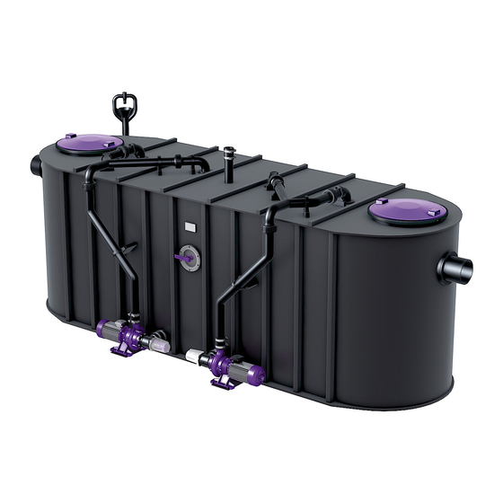
Page 8: Assemblies And Functional Characteristics
Introduction Assemblies and functional characteristics Illustration shows system type F Abb. [3] 1 Inlet 2 Outlet 3 Refill inlet 4 Inspection window 5 Direct disposal pipe 6 Pressure pipe 7 Switchover valve 8 Pump (cleaning and shredding) 9 Pump (disposal) 10 Actuator valve switchover valve (system type F) 11 Control unit (system type D E F) 12 Inspection cover 13 Type plate... -
Page 9: Illustrations And Dimensions
Introduction Illustrations and dimensions Abb. [4] NS 2 1100 1250 1055 1000 1310 200 l 210 l 110 l 410 l NS 4 1560 1810 1055 1000 1310 400 l 350 l 180 l 750 l NS 7 1600 1850 1020 1290 1130... -
Page 10: Illustration System Types - C
Introduction 1.9.1 Illustration system types - C D E F Illustrations of the “Mix” system type for the nominal sizes 2, 4, 7, 10 and 15 Abb. [5] Illustrations of the “Mix” system type for the nominal sizes 20, 25 and 30 Abb. -
Page 11: Illustration System Types - D
Introduction 1.9.2 Illustration system types - D Illustrations of the “Auto Mix” system type for the nominal sizes 2, 4, 7, 10 and 15 Abb. [7] Illustrations of the “Auto Mix” system type for the nominal sizes 20, 25 and 30 Abb. -
Page 12: Illustration System Types - E
Introduction 1.9.3 Illustration system types - E Illustrations of the “Mix & Pump” system type for the nominal sizes 2, 4, 7, 10 and 15 Abb. [9] Illustrations of the “Mix & Pump” system type for the nominal sizes 20, 25 and 30 Abb. -
Page 13: Illustration System Types - F
Introduction 1.9.4 Illustration system types - F C D E Illustrations of the “Auto Mix & Pump” system type for the nominal sizes 2, 4, 7, 10 and 15 Abb. [11] Illustrations of the “Auto Mix & Pump” system type for the nominal sizes 20, 25 and 30 Abb. -
Page 14: Control Unit
Introduction 1.9.5 Control unit 1.9.5.1 “Mix & Pump” control unit for system type E Fettabscheider/Greas Seperator “M“ Ready for operation Alarm LED Start / Stop Start / stop emptying operation Alarm Acknowledge the acoustic alarm Pump operation LED Abb. [13] 1.9.5.2 “Auto Mix &... - Page 15 Introduction Display Number of the menu Name of the menu Abb. [15] 010-917_SON_EN 2019/11 15 / 61...
-
Page 16: Safety
– carrying out of repairs by companies or persons not approved by the manufacturer without the express and written approval of the manufacturer can lead to a loss of warranty. Later extensions to the Kessel grease separator systems must be carried out by Kessel Factory Customer Service. -
Page 17: Hazards Caused By The Product
Safety Hazards caused by the product 2.4.1 Risk caused by electric current and cables All live parts are protected against unintentional contact as well as splashwater from all directions (IP 54). Before housing covers, plugs and cables are opened they must be switched voltage-free. Work on electrical components may only be carried out by specialist st2.2ee 2.2). -
Page 18: Installation
Installation Installation Recommendations for the set-up location / operation – Clean, horizontal set-up area – Well vented or ventilated room and one with level set-up area capable of bearing an appropriate load. – Room temperature at least 15°C. – Sealed floor covering with integrated drain. –... -
Page 19: Fitting The Inlet And Outlet
Installation 3.2.1 Fitting the inlet and outlet C D E F • The system must be set up horizontally on a level surface in a frost-free room. When full, the grease separator system is heavy. Make sure it is placed on a surface with a sufficient load-bearing capacity. • Set up pipework connections to the domestic installation at the inlet and outlet. 3.2.2 Fitting or removing the pump C D E F The intake socket <21>... -
Page 20: Mounting The Refill Inlet
Installation 3.2.3 Mounting the refill inlet C D E F The refill inlet is fitted to the grease separator ready for operation. Grease the seal <45> during conversion. • Use the screw <42> to fit the attachment clamp <34> to the seat <A> on the system tank. 34 42 • Insert the all-round seal <45> into the drill hole <B>. Abb. [17] • Fit the refill inlet <17> into the passage seal <45> and screw tight using the fastening clamp <34>. 3.2.4 Installing the screw-type valve - E The valve must be fitted horizontally. -
Page 21: Installing The Soniccontrol
Installation 3.2.6 Installing the SonicControl sensor (option) - F C D E • Open the inspection cover above the outlet assembly. • Sensor bracket <44> is already screwed <45> to the outlet assembly <43>. • Secure the sensor <42> on the bracket and turn against the stop <81>. -
Page 22: Mounting The Remote Control - F
Installation 3.2.7 Mounting the remote control - F C D E Mount the remote control console in the required position as follows. • Install the screws <52> with dowels <53> (or suitable attachment materials) in such a way that the remote control <54> can be hooked in place. - Page 23 Installation 3.3.1.2 Establishing electrical connections • Establish the connections in accordance with the connection diagram (below and in the housing cover of the control unit). Connection diagram base BASIS BASE OFF ON gr gr bl 2 4 6 NC A2 BUS VERBINDUNG POTENTIAL ZUR ERWEITERUNG...
- Page 24 Installation Connection diagram extension package ERWEITERUNG EXTENSION OFF ON bl gr gr gr L1 L2 2 4 6 NC A2 POTENTIAL FREIER KONTAKT Potential free switch contact Connexion libres de contact max: 42V 0,5A SICHERUNG SICHERUNG Fuse Fuse Fusible Fusible 230VAC 50Hz 230VAC 50Hz F1 315 mAT...
- Page 25 Installation 3.3.1.3 Initialising the control unit Dry running of the pump(s) must be avoided at all costs. Do not press the Start / Stop key! • Switch the power supply on and move the main switch to the ON position, the menu “3.8.1”, page 48 appears on the display.
-
Page 26: Control Unit For System Type E
Installation 3.3.2 Control unit for system type E 3.3.2.1 Installing the “Mix & Pump” control unit The control unit is mounted on the grease separator. To open the control unit proceed as follows: Caution, risk caused by electric current! The control unit may only be opened when the mains power supply has been disconnected. - Page 27 Installation 3.3.2.2 Establishing electrical connections • Establish the connections in accordance with the connection diagram (below and in the housing cover of the control unit). Connection diagram Bei Benutzung der Fernbedienung Brücke entfernen! If remote control is in use remove link! En utilisant la télécommande veuillez enlever le wrapping! 2 4 6 NC A2...
-
Page 28: Control Unit For System Type F
Installation 3.3.2.3 Initialising the control unit The control unit has already been initialised ready for operation. You should still check the presets, however. Dry running of the pump(s) must be avoided at all costs. Do not press the Start / Stop key! •... - Page 29 Installation Installation 3.3.3.2 Establishing electrical connections • Establish the connections in accordance with the connection diagram (below and in the housing cover of the control unit). Connection diagram base BASIS BASE OFF ON 2 4 6 NC A2 BUS VERBINDUNG POTENTIAL ZUR ERWEITERUNG FREIER...
- Page 30 Installation Connection diagram extension package ERWEITERUNG EXTENSION OFF ON bl gr gr gr L1 L2 2 4 6 NC A2 POTENTIAL FREIER KONTAKT Potential free switch contact Connexion libres de contact SICHERUNG SICHERUNG max: 42V 0,5A Fuse Fuse Fusible Fusible 230VAC 50Hz 230VAC 50Hz F1 315 mAT...
- Page 31 If there is a SonicControl (option) connected, answer the question with “yes”, otherwise continue with “no”, the menu Standard appears. If “yes”: • enter password (must be obtained from KESSEL). • Select the system type from the selection displayed and apply by pressing OK, the menu Standardappears. Standard •...
-
Page 32: Initial Filling And Pressure Test
Installation • Select the number of pumps / capacity (see pump type plate(s)) and confirm by pressing OK. Initialisation is completed and the menu with the settings just made appears. System info • There is only one pump installed with nominal sizes 2, 4, 7, 10 and 15. • There are two pumps installed with nominal sizes 20, 25 and 30. •... -
Page 33: Function Check System Type D
Installation 3.4.2 Function check system type D Check the function of the pump(s) • Switch the “Auto Mix” control unit on, menu 0, System info, is displayed. • Press the OK key, menu appears. • Select Maintenance => Manual operation => Cleaning+shredding the pump(s) is/are switched on. -
Page 34: Function Check System Type E
Installation 3.4.3 Function check system type E • Switch the “Mix & Pump” control unit on. Make sure that the switchover valve is not in the “disposal” position, since otherwise the contents of the system tank would be pumped off. • Set the switchover valve <26> to the position cleaning and shredding (handle to the right). - Page 35 Installation Check the function of the actuator valve switchover valve Carry out the following settings in the menu: Maintenance • => empty, the actuator valve moves the valve into the correct position, then the Manual operation Part pump(s) start(s). If the pump(s) start(s) immediately, the valve was already in the designated position. •...
-
Page 36: Operation
Operation Operation The grease separator separates greases, oils and sludge out of the wastewater. Different methods and / or control units are used for emptying the separated substances (see 1.3). Switching on system type C D E F Following a successful function check (see 3.4.1 on page 32) the grease separator is ready for operation. Switching on system type D Following a successful function check (see 3.4.2 Function check system type D on page 33) the grease separator system can be switched on. -
Page 37: Switching On System Type E
Operation Switching on system type E Following a successful function check (see 3.4.3 Function check system type E on page 34) the grease separator system can be switched on. To do this: • Switch the main switch on*. Following a successful system test, the green LED <64>... -
Page 38: Carrying Out Emptying
Carrying out emptying Carrying out emptying General information The emptying cycles of the various system types are adapted to achieving complete emptying of the system tank coupled with best possible cleaning for medium degree of soiling of the wastewater. The pump(s) cannot run dry on account of their design (exception: initial operation or putting back into operation). -
Page 39: Emptying System Type C
Carrying out emptying Emptying system type C D E F Workflow diagram for emptying cycle (Euro standard 1825) Emptying period Emptying vehicle is pumping off Pump(s) in operation (cleaning and shredding) Hot water* supply Cold water supply Time required for the level to drop approx. 10 cm * recommended Abb. -
Page 40: Emptying System Type D
Carrying out emptying Emptying system type D Workflow diagram for emptying cycle (Euro standard 1825) Setting in the menu Emptying period A1 Automatic operation (cleaning and shredding, part filling) A2 Filling of the system tank (started by the user) Emptying vehicle is pumping off Pump in operation (cleaning and shredding) 3.1.1 Valve part fill (hot water supply*) 3.1.2 Valve fill (cold water supply, started by the user) -
Page 41: Emptying System Type E
Carrying out emptying Emptying system type E Workflow diagram for emptying cycle (Euro standard 1825) Emptying period A1 Manual operation (pump operating times) A2 Filling of the system tank (by the user) Emptying vehicle connected Pump in operation (pumping off, to the emptying vehicle) Pump on Pump on (cleaning and shredding) Valve switchover by user... - Page 42 Carrying out emptying Carrying out emptying • Switch the control unit on. • Connect the extraction hose of the emptying vehicle to the direct disposal pipe. • Set the hand lever to emptying. Before actuating the hand lever, make sure that (both) pump(s) is/are out of operation.
-
Page 43: Emptying System Type F
Carrying out emptying Emptying system type F C D E Workflow diagram for emptying cycle (Euro standard 1825) Setting in the menu Emptying period A1 Automatic operation A2 Filling of the system tank (started by the user) Emptying vehicle connected Pump starts running automatically (pumping off, to the emptying vehicle) 1.6.1. - Page 44 Carrying out emptying Carrying out emptying in automatic operation (The steps carried out in automatic operation can be actuated individually via manual operation) • Switch the control unit on. • Set up the hose connection between the emptying vehicle and the direct disposal pipe. •...
- Page 45 Carrying out emptying Carrying out emptying You will find the individual program steps with recommendations for operating time in the table below. Basis for calculation: Disposal times in accordance with Euro standard 1825 with water supply flow solenoid valve 1l/s for DN25 or 3.6 m³/h. Function NS 2 NS 4 NS 7 NS 10 NS 15 General information Part empty 14 s 25 s Empty Lower water level by 10 cm 70 s 130 s 215 s 305 s...
- Page 46 Carrying out emptying Function NS 20 NS 25 NS 30 General information Part empty 35 s 36 s 37 s Empty Lower water level by 10 cm 770 s 945 s 1135 s Flush Empty 325 s 336 s 396 s Empty Until the pump runs empty Fill...
-
Page 47: Settings, Operating Menu
Settings, operating menu Settings, operating menu System type D “Auto Mix” control unit For general information and “Activating operating mode” see 6.3 Operating menu System info Information Hours of operation 1.1.1 Total running time 1.1.2 Run time pump 1.1.3 Pump starts 1.1.4 Power outage Log book... - Page 48 Settings, operating menu Settings Parameters 3.1.1 Cleaning+shredding 3.1.2 Valve part fill Carry out setting in agreement with Factory Customer Service 3.1.3 Valve fill 3.1.4 On delay 3.1.5 Legionella flushing interval 3.1.6 Legionella flushing, cold 3.1.7 Legionella flushing, hot 3.1.30 Access remote control Profile memory 3.2.1 Save parameters 3.2.2 Load parameters Date/time* Number of pumps* 3.4.1...
-
Page 49: System Type E
Settings, operating menu System type E “Mix & Pump” control unit Settings Set the nominal sizes using the dip switche(see 3.3.2.3 Initialising the control unit on page 28). System type F C D E “Auto Mix & Pump” control unit General information Fettabscheider/Grease Seperator „PV+S“... - Page 50 Settings, operating menu Operating menu System info Information Hours of operation 1.1.1 Total running time 1.1.2 Run time pump 1.1.3 Pump starts 1.1.4 Power outage 1.1.5 Runtime SonicControl 1.1.6 Op. above alarm level 1.1.7 Op. above alarm temp. 1.1.8 Number of emptying cycles Log book 1.2.1 most recent I&F...
- Page 51 Settings, operating menu 1.6.24 Level comparison 1.6.30 Access remote control Measuring data 1.7.1 Last layer thickness and temperature determined 1.7.2 Layer thickness and temperature determined before that 1.7.3 Layer thickness and temperature determined before that 1.7.4 … Emptying 1.8.1 Last emptying Maintenance Manual operation 2.1.1...
- Page 52 Settings, operating menu 3.1.9 Empty 3.1.10 Fill 3.1.11 Flush 3.1.12 Empty 3.1.13 Fill 3.1.14 Cleaning program 3.1.15 Legionella flushing interval 3.1.16 Legionella flushing, cold 3.1.17 Legionella flushing, hot 3.1.18 Alarm layer thickness 3.1.19 Pre-alarm layer thickness 3.1.20 Alarm temperature 3.1.21 Start of measuring range 3.1.22 End of measuring range 3.1.23 Measuring interval 3.1.24...
- Page 53 Settings, operating menu 3.7.7 Text message-Destination 2 3.7.8 Text message-Destination 3 3.7.9 Status Language* 3.8.1 Deutsch 3.8.2 English 3.8.3 Français 3.8.4 Italiano 3.8.5 Nederlands 3.8.6 Polski Expert mode 3.9.1 On delay 3.9.2 Limit running time 3.9.3 Conductivity 3.9.4 Density 3.9.5 Trigger 3.9.6 3.9.7...
-
Page 54: Technical Data
Technical data Technical data Pre-conditions / basis for calculation The parameters for operation (emptying) of the grease separator system are based on the following values: – Pumping quantity (extraction capacity) of the emptying vehicle 10 l/s = 36m³/h. – Cold / hot water supply 1l/s with DN25 –... -
Page 55: Torques
Technical data Torques Description / use Torque Nm Spanner size Door hinge screw A2 bright 6x40 4.5 ±0.5 PT-screw 100x30 A2 PT-screw KB60x30 WN 1411 4.5 ±0.5 Metal clamp / on system tank ISK 10 mm Hexagon safety screw M8x30 Spanner socket 13 mm Pipe clamp D=120... -
Page 56: Maintenance
Maintenance Maintenance Before housing covers, plugs and cables are opened they must be switched voltage-free. Work on electrical components may only be carried out by specialist st2.2 on page 16). Maintenance intervals The maintenance date for the grease separator system can be set in the menu 2. -
Page 57: Troubleshooting
Maintenance Troubleshooting Fault Possible cause Action(s) Pumping Pumping height too large for the Use the pump on the emptying vehicle (suction) to support the capacity too low pump capacity grease separator system pump during emptying No or too little Room temperature under 15°C Heat longer, increase room temperature grease is flowing Slow build-up of a solid grease layer... - Page 58 Maintenance Temperature fault Winding temperature switch has Self-resetting when motor has cooled down, acknowledge triggered fault message with alarm key, please contact Customer Services if further temperature fault messages are issued Undercurrent The minimum current of the pump is Check cable and repair if necessary not being reached.
-
Page 59: Clean The Grease Separator
Maintenance Permanent odour development Fault Possible cause Action Odour pollution Wastewater pipes leaking. Check firm fit and seals, repair if necessary No venting pipe, cross-section too Retrofit on-site small Closed room with no air exchange Create ventilation possibilities, forced ventilation System parts are leaking Eliminate leaks Clean the grease separator •... -
Page 60: System Passport / Factory Approval
System passport / factory approval System passport / factory approval 010-917_SON_EN 60 / 61 2019/11... -
Page 61: General Inspection / Maintenance Requirements
General inspection / maintenance requirements General inspection / maintenance requirements The owner-operator of a separator system is obliged according to valid legal principles as well as according to DIN EN 1825 / DIN 4040-100 to subject the system to a general inspection with watertightness test before commissioning and repeated every 5 years.
Need help?
Do you have a question about the EasyClean free NS 4 and is the answer not in the manual?
Questions and answers