Kessel EasyClean free NS 2 Installation, Operation And Maintenance Manual
Hide thumbs
Also See for EasyClean free NS 2:
Table of Contents
Advertisement
Quick Links
INSTRUCTIONS FOR INSTALLATION, OPERATION AND
KESSEL Grease separator EasyClean free
Standard, Direct - oval
in NS 2, 4, 7, 10, 15, 20, 25, 30
for set-up in frost-free rooms
Installation
Initial operation
for the system was carried out by your specialist company:
Name/signature
As at 2018/01
MAINTENANCE
Instructional briefing
Date
Town/City
Product advantages
in accordance with DIN 4040
in accordance with Euro
standard EN 1825
100% resistance to aggressive
fatty acids
Easy operation
Upgrade to all
variants possible
20-year guarantee
for the tank
Stamp of specialist company
Part No. 010-916_SON_EN
GB
Page 1-18
Advertisement
Table of Contents

Related Manuals for Kessel EasyClean free NS 2


Summary of Contents for Kessel EasyClean free NS 2
- Page 1 INSTRUCTIONS FOR INSTALLATION, OPERATION AND MAINTENANCE KESSEL Grease separator EasyClean free Page 1-18 Standard, Direct - oval in NS 2, 4, 7, 10, 15, 20, 25, 30 for set-up in frost-free rooms Product advantages in accordance with DIN 4040 in accordance with Euro...
-
Page 2: Table Of Contents
Table of Contents Introduction Product description, general ..................... 4 Use............................ 4 System types ........................5 Article number overview ....................5 Nameplate ........................6 Scope of delivery ......................6 General information on these operating and maintenance instructions ......6 Assemblies, functional characteristics and dimensions ............ 7 1.8.1 Figure: system type A ....................... - Page 3 Table of Contents Technical data Pre-conditions / basis for calculation ................15 Torques ..........................15 Maintenance Maintenance intervals ....................... 16 Troubleshooting ........................ 16 Clean the grease separator ....................16 System passport / factory approval General inspection / maintenance requirements 2018/01 3 / 18 010-916_SON_EN...
-
Page 4: Introduction
Introduction Introduction Dear Customer, We are pleased that you have decided to buy one of our products. We are certain that it will fully meet your requirements. These installation, operating and maintenance instructions contain important information that has to be observed during installation, assembly, operation, maintenance and repair. -
Page 5: System Types
Introduction System types The following versions of the grease separator are produced: System type A: “Standard” - without direct disposal pipe System type B: “Direct” - with direct disposal pipe System components, system type A: - Separator for sludge and grease System components, system type B: - Separator for sludge and grease - Direct disposal pipe... -
Page 6: Nameplate
Introduction Nameplate Information on the grease separator system nameplate 10 Hardware revision status 52 Material description 53 Material number 55 Standard Bahnhofstraße 31 D-85101 Lenting 56 Free text / explanation 57 Free text / explanation 58 Free text / explanation 59 Free text / explanation Made in Germany 75 Free text / explanation... -
Page 7: Assemblies, Functional Characteristics And Dimensions
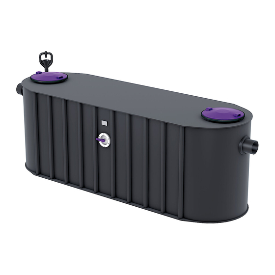
Introduction Assemblies, functional characteristics and dimensions Abb. [2] Note: Figure shows system type B 1 Inlet 2 Outlet 3 Cover 4 Direct disposal pipe DN65 (for system type B) NS 2 1100 1250 1000 1310 200 l 210 l 110 l 410 l NS 4 1560... -
Page 8: Figure: System Type A
Introduction 1.8.1 Figure: system type A Abb. [3] 1.8.2 Figure: system type B Abb. [4] 010-916_SON_EN 8 / 18 2018/01... -
Page 9: Safety
– carrying out of repairs by companies or persons not approved by the manufacturer without the express and written approval of the manufacturer can lead to a loss of warranty. Later extensions to the Kessel grease separators must be carried out by Kessel Factory Customer Service. Personnel selection and qualification People who operate and/or install the grease separator must –... -
Page 10: Organisational Safety Measures
Safety Organisational safety measures The operating and maintenance instructions must always be kept near the grease separator system. Hazards caused by the product 2.4.1 Risk of slipping when the system is emptied During cleaning work, greasy liquid and/or grease can wet the floor. This results in a slipping hazard. Always remove any liquid and/or grease that has leaked immediately, and wear suitable footwear. 2.4.2 Risk of infection in case of contact with the wastewater The wastewater contains bacteria. -
Page 11: Installation
Installation Installation Recommendations for the set-up location / operation – clean, horizontal set-up area – well vented or ventilated room and one with level set-up area capable of bearing an appropriate load. – room temperature at least 15°C. – Sealed floor covering with integrated drain. –... -
Page 12: Initial Filling And Pressure Test
Installation Initial filling and pressure test • Make sure that there are no external materials or soiling in the grease separator. • Check the system for airtightness, transport and installation damage and check the pipe connections. • Fill the complete grease separator system with water (up to system overflow on the outlet<35>). • Carry out pressure test, to do this •... -
Page 13: Carrying Out Emptying
Carrying out emptying Carrying out emptying Emptying / disposal process in general • Operating instructions must be displayed near the separator. • The disposal procedure must be carried out exactly according to the instructions. • Only allow approved disposal companies to carry empty out the grease separator. •... -
Page 14: Emptying System Type A
Carrying out emptying Emptying system type A • Carefully loosen the clamping ring and remove the inspection cover (Caution! Risk of injury) • Move the suction spout of the disposal vehicle past the feed or drain part and empty / extract the contents of the system tank (Caution! Damage to the installed components leads to problems with the separating function. ) • When the system tank is about 1 third empty, open the hot water inlet. •... -
Page 15: Technical Data
Technical data Technical data Pre-conditions / basis for calculation The parameters for operation (emptying) of the grease separator system are based on the following values: – Pumping quantity (extraction capacity) of the disposal vehicle 10 l/s = 36 m³/h. – Cold / hot water supply 1l/s with DN25 –... -
Page 16: Maintenance
Maintenance Maintenance Maintenance intervals The grease separator system must be serviced once a year by a qualified person*. In addition to emptying, the following jobs must be carried out: *The term “qualified” is used to describe employees at the owner-operators or from third parties who, on account of their training, knowledge and practical experience, can guarantee that they carry out evaluations or tests in a professional way in the respective field. – Check on the inner walls of the sludge trap and the grease separator. –... -
Page 17: System Passport / Factory Approval
System passport / factory approval System passport / factory approval 2018/01 17 / 18 010-916_SON_EN... -
Page 18: General Inspection / Maintenance Requirements
General inspection / maintenance requirements General inspection / maintenance requirements The owner-operator of a separator system is obliged according to valid legal principles as well as according to DIN EN 1825 / DIN 4040-100 to subject the system to a general inspection with watertightness test before commissioning and repeated every 5 years.
Need help?
Do you have a question about the EasyClean free NS 2 and is the answer not in the manual?
Questions and answers