Table of Contents
Advertisement
Available languages
Available languages
Quick Links
ANLEITUNG FÜR EINBAU, BEDIENUNG UND WARTUNG
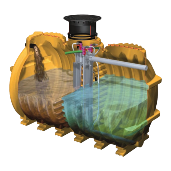
KESSEL-Kleinkläranlagen INNO-CLEAN
- die vollbiologische Kleinkläranlage
zur Reinigung häuslichen Abwassers
nach EN 12566, Teil III
INNO-CLEAN
zum Einbau ins Erdreich
in den Nenngrößen
EW 4 bis EW 50
Installation
der Anlage wurde durchgeführt von Ihrem Fachbetrieb:
Name/Unterschrift
Stand 12/2011
+
-Kleinkläranlage
Inbetriebnahme
Datum
Bedienungsanleitung
Instructions de Montage
Installation Manual
Instrukcja Zabudowy
Istruzion per l'installazione
Produktvorteile
Geringe Energiekosten
Geringe Wartungs- und Instandhaltungs-
kosten
Hohe Standzeit
durch Behälter aus Kunststoff
Dauerhafte Dichtheit durch
monolithisch rotierten Behälter
Keine Schwefelkorrosion
Leichter Einbau durch geringes Gewicht
Hohe Bruchsicherheit durch PE
Reinigungsklassen C, D, D+P
Zulassungen:
Z-55.3-184, Z-55.3-185, Z-55.3-187
Einweisung
Ort
+
Anleitung kann über
www.kessel.de
im Format DIN A 4
heruntergeladen werden!
Page 48-91
Page 92-135
str. 136-179
pag. 180-224
Stempel Fachbetrieb
Seite 1-47
Sach-Nr. 010-430
Advertisement
Chapters
Table of Contents

Related Manuals for Kessel INNO-CLEAN


Summary of Contents for Kessel INNO-CLEAN
- Page 1 ANLEITUNG FÜR EINBAU, BEDIENUNG UND WARTUNG KESSEL-Kleinkläranlagen INNO-CLEAN - die vollbiologische Kleinkläranlage Anleitung kann über zur Reinigung häuslichen Abwassers www.kessel.de im Format DIN A 4 nach EN 12566, Teil III heruntergeladen werden! Bedienungsanleitung Seite 1-47 INNO-CLEAN -Kleinkläranlage Instructions de Montage...
- Page 3 1. Sicherheitshinweise Achtung Erstickungsgefahr beim Betreten der Anlage Das Personal für Montage, Bedienung, Wartung und Reparatur muss die entsprechende Qualifikation für diese Arbeiten aufweisen. Der Verantwortungsbereich, die Zuständigkeit und die Überwachung des Personals müssen durch den Betreiber genau geregelt sein. Die Betriebssicherheit der gelieferten Anlage ist nur bei bestimmungsgemäßer Verwendung gewähr- leistet.
-
Page 4: Table Of Contents
Inhaltsverzeichnis ......................Seite 1. Sicherheitshinweise 2.1 Einsatzbereich ................ Seite 2. Allgemeines 2.2 Anlagenbeschreibung .............. Seite 2.3 Anlagenkonfiguration .............. Seite 2.4 Maße und Nutzvolumen ............Seite 2.5 Funktionsbeschreibung ............Seite 13 3.1 Verpackung................Seite 15 3. Verpackung, Transport 3.2 Transport ................. Seite 15 und Lagerung 3.3 Lagerung ................. - Page 5 Sehr geehrter Kunde, wir freuen uns, dass Sie sich für ein Produkt von KESSEL entschieden haben. Die gesamte Anlage wurde vor Verlassen des Werkes einer strengen Qualitätskontrolle unterzogen. Prüfen Sie bitte den- noch sofort, ob die Anlage vollständig und unbeschädigt bei Ihnen angeliefert wurde. Im Falle eines Transportschadens beachten Sie bitte die Anweisungen in Kapitel „Gewährleistung“...
-
Page 6: Einsatzbereich
Steuerung sind zum freien Einbau in frostgeschützten, überflutungssicheren und trockenen Räumen vorgesehen. Teil III. Für Niederschlagsabwässer, Abwässer aus der Tier- Die Zuleitung muß rückstaufrei an die INNO-CLEAN ange- haltung sowie Schwimmbadabwässer ist diese Anlage nicht vorgesehen. In einem biologischen Verfahren, reinigt diese schlossen werden. -
Page 7: Anlagenkonfiguration
2. Allgemeines 2.3 Anlagenkonfiguration Seitenansicht Behälter EW 4 - 6 Nutzvolumen 4800 l Seitenansicht Behälter EW 8 -10 Nutzvolumen 7600 l Frontansicht... -
Page 8: Maße Und Nutzvolumen
2. Allgemeines 2.4 Maße und Nutzvolumen... - Page 9 2. Allgemeines Anlagenkonfiguration EW 4, EW 6, EW 8 und EW 10...
- Page 10 2. Allgemeines Anlagenkonfiguration EW 12, EW 14, EW 16 und EW 20...
- Page 11 2. Allgemeines Anlagenkonfiguration EW 22 bis EW 30...
- Page 12 2. Allgemeines Anlagenkonfiguration EW 32 bis EW 50...
-
Page 13: Funktionsbeschreibung
2. Allgemeines 2.5 Funktionsbeschreibung Der Klärprozess wird vollautomatisch von der Steuereinheit geregelt. Ein Klär- zyklus dauert ca. 8 Stunden und wird durch Abführen des geklärten Wassers beendet. Der Klärungsprozess basiert auf Mikro- organismen, die während der Behand- lungsphase das Abwasser reinigen. 1. - Page 14 2. Allgemeines Nach der Behandlungsphase folgt eine zweistündige Absetzphase. Alle in dem Ab- wasser enthaltenen Feststoffe, sowie der Belebtschlamm setzen sich am Beckenbo- den ab somit bildet sich im oberen Bereich eine Klarwasserschicht und am Boden eine Schlammschicht aus Mikroorganismen. 5.
-
Page 15: Verpackung
3. Verpackung, Transport und Lagerung • Die Behälter sind gegen unzulässige Lageveränderungen Das Kapitel Sicherheitshinweise ist zu beachten während der Beförderung zu sichern. Durch die Art der Be- festigung dürfen die Behälter nicht beschädigt werden. 3.1 Verpackung Eine Verpackung der Behälter zum Zwecke des Transports bzw. -
Page 16: Einbauort
Beginn der Bauarbeiten festgestellt werden. Eine aus- reichende Ableitung (Drainage) von Sickerwässern ist bei wasserundurchlässigen Böden zwingend notwendig. Die Die größeren INNO-CLEAN -Anlagen bestehen aus zwei oder mehr Behältern. Diese lassen sich individuell in verschiedenen Varianten anordnen. So können auftretenden Belastungsarten wie max. -
Page 17: Einsetzen
Für die Durchführung durch die Gebäudewand emp- den. Die einzelnen Lagen des Verfüllmaterials sollten nicht fiehlt KESSEL auf handelsübliche Wanddurchführungen höher als 30 cm sein. Sie sind mit leichten Verdichtungs- zurück zu greifen (siehe Bild). Zur Abdichtung des Kabel-... -
Page 18: Verlegung Der Verbindungsleitungen
B. Fa. Steelter oder Inno-Clean Gefälle mind. 2° Fa. DOYMA DN 100 fallend zum Behälter leerrohres im Gebäude, sollte die Abdeckung von KESSEL 4.8 Verlegung der Verbindungsleitungen zur Steuer- (Kabelleerrohrabdichtung Art.-Nr. 97711) zum Schutz vor einheit (Belüftungsschlauch und Steuerleitung) Geruchsbelästigungen eingesetzt werden. -
Page 19: Montage Der Aufsatzstücke
4.9 Montage der Aufsatzstücke Zuerst die Dichtung (siehe Zeichnung 4.9) in die vorgesehe- ne Sicke im Dom einlegen. Das teleskopische KESSEL-Aufsatzstück im unteren Be- reich mit Gleitmittel einfetten und in die Behälteröffnung ein- stecken, in die gewünschte Position bringen und mittels Klemmring fixieren. -
Page 20: Befüllen
4. Einbau und Montage Die Dichtlippe soll auf der Innenseite des Ringes nach unten zeigen. ➔ ➔ Auslauf Zulauf 4.10 Abschließende Befüllung des Behälters Vor dem Verfüllen nochmaliges Kontrollieren der Zu- und Ablaufleitung, sowie der Entlüftungsleitung und des Kabelleerrohrs. Das Aufsatzstück mit der Geländeoberkante abgleichen. -
Page 21: Einbau Steuereinheit Und Verdichter
Allgemeine Hinweise Gasen oder Dämpfen sein. ACHTUNG: KESSEL empfiehlt, für die Ausführung von Die Schlauchleitung ist so kurz und so gerade wie möglich elektrischen Anschlüssen, einen Fachbetrieb des Elek- zwischen Steuerung und Behälter zu verlegen. Richtungs- trohandwerks zu beauftragen. - Page 22 4. Einbau und Montage Montage und Anschluß Die Wandkonsole (optionales Zubehör) oder eine alternative Abstellmöglichkeit ist waagerecht an der Wand zu fixieren. Das Steuergerät durch Lösen der vier stirnseitigen Kreuzschlitzschrauben öffnen und dessen Rückwand mit den mitgelieferten vier Kreuzschlitzschrauben an den vorgebohrten Stellen der Wandkonsole (unter- halb der Abstellfläche für den Verdichter) befestigen.
- Page 23 4. Einbau und Montage Optionale Anschlüsse am Schaltgerät: Achtung: Alle optionalen Anschlüsse sind nur durch Elektrofachkräfte durchzuführen.
-
Page 24: Anlage In Betriebsbereitschaft Setzen
Einweisung / Übergabe ausgerüstet sein. Das Kapitel Sicherheitshinweise ist zu beachten! (S.2) Die Inbetriebnahme wird von einem Fachbetrieb oder einem Systemstart Systemdiagnose KESSEL-Beauftragten durchgeführt (gegen Aufpreis). Folgende Personen sollten bei der Übergabe anwesend sein: - Abnahmeberechtigter des Bauherrn Sprache - Fachbetrieb deutsch französisch... -
Page 25: Pflichten Des Betreibers
5. Inbetriebnahme Bei der Erstinitialisierung der Anlage fragt das Steuer- Darüber hinaus kann es sinnvoll sein, nach jeder Primär- gerät nach vier Grundeinstellungen. Im Display des schlammentsorgung (siehe Punkt 6.4 Entsorgung) die Steuergerätes erscheint die Frage nach: Einstellung T20 ("Rückführung Urlaubsphase") zu redu- 1. -
Page 26: Eigenkontrolle Des Betreibers
6. Betrieb und Entsorgung Wenn Sie sich an nachfolgende Empfehlungen halten, kön- sicherstellen, dass sich je nach Betriebsbedingungen, nen Sie unnötige Reparaturkosten vermeiden und die Le- zwischen 300 ml/l bis 600 ml/l Belebtschlamm im Bele- bensdauer Ihrer Anlage erhöhen: bungsbecken befindet. Sollte dieser Wert nicht erreicht sein, reduzieren oder erhöhen Sie die voreingestellten •... -
Page 27: Was Nicht In Die Biol. Kleinkläranlage Gehört
6. Betrieb und Entsorgung Halbjährliche Kontrollen Wartung durch einen Fachbetrieb. Dabei sind die Vorgaben der zuständigen Behörden zu beachten. Bei einer Schlamm- höhe von 95 cm vom Behälterboden sind ca. 70 % der Aufnahmekapazität erreicht. 6.3 Was nicht in eine biologische Kleinkläranlage gehört Folgende Hinweise sollten Sie im eigenen Interesse beachten: Feste oder flüssige Stoffe, Was sie anrichten... -
Page 28: Entsorgung
Bei 70% der Aufnahmemenge der Kleinkläranlage, das ent- spricht ca. 95 cm, ist der Inhalt des Schlammfanges durch Wichtiger Hinweis: KESSEL empfiehlt, bei der Entsorgung des Schlammfangs einen Entsorgungsfachbetrieb zu entsorgen (Messung siehe bzw. der Vorklärkammer (insbesondere bei eher unterlastig 6.2 Eigenkontrolle des Betreibers oder durch Wartungs-... -
Page 29: Vorklärung Und Belebung
7. Wartung Anschließend setzen Sie den Heber wieder in die entspre- 7.1 Wartung Vorklärung + Belebung chende Position und schließen ihn wieder korrekt an. Hinweis: Informieren Sie sich, wer in Ihrem Gebiet für die • Sollte es aufgrund eines unzureichenden Belüftungsbildes Wartung von Kleinkläranlagen zuständig ist. -
Page 30: Verdichter
Einbau- und Bedienungsanleitung beachten. - Sind abnormale Geräusch oder Vibrationen zu vernehmen? Eine Ersatzteilliste erhalten Sie über den Kundendienst der - Ist die Temperatur des Verdichters normal oder evtl. zu KESSEL . hoch? - Zeigt das Netzkabel etwaige Schäden auf? - Page 31 7. Wartung...
- Page 32 8. Steuerung der Kleinkläranlage 8. Bedienung des Schaltgerätes Display/Anzeigenfeld Bewegungstasten/Richtungstasten Bestätigungstaste/OK-Taste Zurücktaste/ESC-Taste Kontrolllampe für Betriebsbereitschaft Kontrolllampe für Störungsmeldung Netzabschlusskabel Netzanschlus für Verdichter Anschluss Druckluftsensor Anschlussmöglichkeiten für externen Signalgeber Anschluss für Ventilblock Anschlussbuchse für potentialfreien Kontakt Menüführung Alarmtaste kann der akustische Alarm quittiert werden. Die Menüführung des Schaltgerätes ist in die Systeminfo, Der Stand-by-Modus wird für mind.
-
Page 33: Systemmenü
8. Steuerung der Kleinkläranlage Die neue Steuerung 8.1.System-Menü Informationen Systeminfo Uhrzeit: 00:00:00 Schwimmer 1: Ein / Aus TX: (Phase T1 bis T24) Wartung TX1: (Zeit: 00:00:00) Einstellungen Anzeige der Hierarchie-Ebene Uhrzeit Anzeige der aktivierten Schwimmer, sowie deren Position Anzeige der Phase Anzeige der aktuell abgelaufenen Zeit der jeweil. -
Page 34: Einstellungsmenü
8. Steuerung der Kleinkläranlage dichter wird hierbei nicht eingeschaltet. 8.3.3 Wartungstermin Eingabe des nächsten Wartungstermins durch den Wartungspartner. 8.4.1 Parameter Die neue Steuerung 8.4 Einstellungsmenü Änderung werkseitig hinterlegter Parameter. Hinweis: Jede Änderung wird mit Bestätigung der Parameter OK-Taste sofort übernommen. Zusätzlich gibt es Systeminfo Informationen Parameterspeicher... -
Page 35: Seite
Drucks der Drucküberwa- keit des Verdichters (siehe Kapitel Wartung) chung - Undichtigkeit im System - Überprüfung aller Anschlüsse der INNO-CLEAN ® und Schläuche auf mögliche Leckagen Überstrom - Wert zu niedrig eingestellt - Einstellung auf 2,0 A... - Page 36 9. Störungen und Abhilfemaßnahmen Fehler Mögliche Ursache Behebung Akkuspannung zu hoch - Akku nicht vorhanden - Akku einsetzen - Akku auf Polarität und Sitz prüfen - Kontaktfehler am Akku - Schaltgerät tauschen - Relaiskontakt im Schaltgerät “ver- Relaisfehler klebt” - Die Anlage ist stromlos - Vorsicherung und/oder Auf dem Display der Steuerung FI-Schalter überprüfen...
- Page 37 9. Störungen und Abhilfemaßnahmen Fehler Mögliche Ursache Behebung - Ist beim Handbetrieb Klarwasser- - Magnetventil defekt. abzug kein deutliches Öffnungs- geräusch feststellbar, Service an- rufen. - Die Einleitungsstelle muss wieder - Es kommt zum Rückstau an der freigängig gemacht werden. Einleitungsstelle.
-
Page 38: Seite
10. Gewährleistung 1. Ist eine Lieferung oder Leistung mangelhaft, so hat KESSEL Über die gesetzliche Regelung hinaus erhöht die KESSEL AG die nach Ihrer Wahl den Mangel durch Nachbesserung zu beseitigen Gewährleistungsfrist für Leichtflüssigkeitsabscheider, Fettab- oder eine mangelfreie Sache zu liefern. Schlägt die Nachbesse- scheider, Schächte, Kleinkläranlagen und Regenwasserzister-... - Page 39 Anlagenpaß / Werksabnahme...
- Page 40 12. Konformitätserklärung...
-
Page 41: Seite
13. Betriebstagebuch (Kopiervorlage) Wöchentliche Kontrollen der Betriebszeiten (h) Datum Gesamt- Belüftung Klarwasser- Schlamm- Besondere Vorkommnisse laufzeit schickung abzug abzug... - Page 42 14. Wartungscheckliste Stammdaten Standort: ____________________________ Name des Betreibers: _____________________________ Anlagengröße: ____________________________ Typ der Anlage: _____________________________ Seriennummer: ____________________________ Reinigungsklasse: _____________________________ Uhrzeit: ____________________________ angeschlossene Einwohner / Einwohnergleichheit: Datum: ____________________________ Kontrolle Mängel Bemerkung Anlagenteil / Funktion nein nein Erster Eindruck Einbausituation Behälter Einbausituation Heber / Pumpen Einbausituation Schläuche + Kabel Entlüftungsleitung Schaltgerät Gibt es oder gab es Fehlermeldungen?
-
Page 43: Seite
Anschluss für serielle Schnittstelle COM1 über 5poligen Pfostenstecker (Option) • Anschluss für zweiten Schwimmerschalter 230 Vac über 3 Klemmen (Option) • Anschluss für Fernsignalgeber 20 m Leitung 2x0,75 qmm (KESSEL-Nr. 20162) (Option) • Anschluss für Verdichter über Schutzkontakt Kupplung •... - Page 44 16. Ersatzteile Artikelnummer Anlage allgemein Aushebeschlüssel 160-044 Schaltgerät 331-105 ZSB Drucküberwachung 331-164 ZSB Ventilblock mit Schwimmerschalter 331-106 Spannmuffe 163-041 Luftschlauch 19x25 mm (15m) 331-076 T-Stück DN 25 003-488 Startbakterien Typ Sprinter 331-062 Startbakterien Typ Ammon 331-063 Kompressor Membrankompressor EL 100 331-020 Membrankompressor EL 150 331-029...
- Page 45 Notizen...
- Page 46 Telefon / Telefax __________________________________________________________ Planer __________________________________________________________ Adresse __________________________________________________________ Telefon / Telefax __________________________________________________________ Ausführende Sanitärfirma __________________________________________________________ Adresse __________________________________________________________ Telefon / Telefax __________________________________________________________ KESSEL-Kommissions-Nr.: Abnahmeberechtigter __________________________________________________________ Adresse __________________________________________________________ Telefon / Telefax __________________________________________________________ Anlagen-Betreiber __________________________________________________________ Adresse __________________________________________________________ Telefon / Telefax __________________________________________________________ Übergabeperson __________________________________________________________...
- Page 48 NOTICE D´INSTALLATION, DE MONTAGE ET D´ENTRETIEN Micro station d'épuration KESSEL INNO-CLEAN Micro station d'épuration totalement biologique pour le traitement des eaux usées ménagères, selon la EN 12566, partie III Micro station d´épuration L´ínstruction INNO-CLEAN pour une de service peut être Installation à...
- Page 49 1. Consignes de sécurité Attention Risque d'asphyxie en cas d´intervention dans la cuve. Le personnel affecté au montage, à la manipulation, à la maintenance et aux réparations doit présenter la qualification correspondant à ces travaux. L'exploitant doit dicter les règles exactes concernant les domaines de responsabilité, les compétences et la surveillance du personnel.
- Page 50 Sommaire ......................Page 49 1. Consignes de sécurité 2.1 Champ d'application ............... Page 52 2. Généralités 2.2 Description du système ............Page 52 2.3 Configuration de l´installation..........Page 53 2.4 Dimension et volume............... Page 54 2.5 Description du fonctionnement ..........Page 59 3.1 Emballage................
- Page 51 Cher client, Nous nous réjouissons que vous vous soyez décidé en faveur d'un produit de KESSEL. L'ensemble du système a été soumis à un contrôle de qualité sévère avant de quitter l'usine. Veuillez contrôler immédia- tement si le système a bien été livré chez vous complet et sans dommages. Veuillez tenir compte, en cas de dommages pendant le transport, des instructions du chapitre «...
-
Page 52: Généralités
2. Généralités pour l'étayage en terre. L'aération et la circulation sont ent- 2.1 Champ d'application INNO-CLEAN , le système d'épuration de KESSEL est un ièrement régulées automatiquement par une unité de com- système de nettoyage pour les eaux usées ménagères con- mande. -
Page 53: Configuration De L´installation
2. Généralités 2.3 Configuration des installations Vue de face, Cuve EQ 4 - 6 volume utile 4800 l Vue de face, conteneur EQ 8-10 volume utile 7600 l Vue de face... -
Page 54: Dimension Et Volume
2. Généralités 2.4. Masse et volume utile... - Page 55 2. Généralités Configuration des installations EQ 4, EQ 6, EQ 8 EQ et 10 Elément de renvoie des eaux claires Bac de prélèvement Trop plein Elément de renvoie d'excédent de boue Capteur de chargement Commutateur de flotteur Cartouche de ventilation aérateur Entrée kg/d BSB5 Fret/jour...
- Page 56 2. Généralités Configuration des installations EQ 12, EQ 14, EQ 16 et EQ 20 Elément de renvoie des eaux claires Bac de prélèvement Trop plein Elément de renvoie d'excédent de boue Capteur de chargement Commutateur de flotteur Cartouche de ventilation aérateur Entrée kg/d BSB5 Fret/jour...
- Page 57 2. Généralités Configuration des installations EQ 22 - EQ 30 Elément de renvoie des eaux claires Bac de prélèvement Trop plein Capteur de chargement Elément de renvoie d'excédent de boue Commutateur de flotteur Cartouche de ventilation aérateur 2 Cartouche de ventilation aérateur1 Dépôt de matière lourde et décantation de boues Aération...
- Page 58 2. Généralités Configuration des installations EQ 32 - EQ 50...
-
Page 59: Description Du Fonctionnement
2. Généralités 2.5. Description du fonctionnement Le processus d'épuration est automatique- ment régulé par le gestionnaire. Un cycle d'épuration dure environ 8 heures et se ter- mine par l’évacuation de l'eau purifiée. Le processus de clarification se base sur des micro-organismes qui se charge de la puri- fication des eaux. - Page 60 2. Généralités 4. Phase de décantation Une phase de décantation de 2 heures suit la phase de traitement. Toutes Les matières solides contenues dans les eaux usées ainsi que la boue activée se déposent au fond du bassin, ce qui est l’origine de for- mation d´une couche d'eau claire dans la zone supérieure, tandis qu’une couche de boue des micro-organismes se dépose au...
-
Page 61: Emballage, Transport
3. Emballage, transport et stockage Il faut tenir compte du chapitre traitant des consignes Les réservoirs doivent être sécurisés contre tout change- de sécurité ment de position non autorisé pendant leur convoyage. Les réservoirs ne doivent pas être endommagés par le type de 3.1 Emballage fixation. -
Page 62: Installation Et Montage
DIN 18196). ). Le niveau de la nappe phréatique pouvant être présent doit également avoir été déterminé avant le début des travaux de construction. Un drainage suf- Les plus grandes installations INNO-CLEAN ® se composent de deux ou de da- fisant des eaux d’infiltration est souvent nécessaire en cas... -
Page 63: La Pose
4.6 Remblayage de la fouille La liaison entre le boîtier de commande / compresseur et En règle générale, le remplissage de la cuve et le rem- bloc de soupape / cuve INNO-CLEAN sera assurée par blayage de la fouille doivent être réalisés parallèlement. Le une gaine pour câbles (tube KG en PVC et de dimension... -
Page 64: Montage Des Tuyaux Pneumatiques
Il faut alors utiliser les couronnes de scie clo- Flexibles pour les airs lifts che originales et les joints de passage pour tube de KESSEL 4.8 Pose des lignes de connexion pour l’unité de comman- (KESSEL - Scie cloche DN 50 - DN 150, référence 50100) de (tuyau flexible de ventilation et ligne de commande) Dispositif d´étanchéité... -
Page 65: Mise En Place Des Rehausses
Avec un lubrifiant, graisser la partie bisoute de la rehausse KESSEL et le joint et emboiter dans le trous d´homme jus- qu’à la position souhaité, puis fixer au moyen d’un collier de serrage. Un ajustage de précision à la hauteur définitive peut être effectué... -
Page 66: Remplissage Final
4. Installation et montage Les langette du joint doivent être orienté vers le fond de cuve. ➔ ➔ Sortie Entrée 4.10 Remplissage finale de la cuve de ventilation et la gaine pour câbles. Egaliser la rehausse Avant de procéder au remplissage, vérifier une dernière par rapport au terrain fois l'alimentation entrée et de sortie, ainsi que la conduite... -
Page 67: Installation Du Gestionnaire Et Du Compresseur
Instructions générales La tuyauterie flexible doit être aussi courte et rectiligne que ATTENTION : KESSEL recommande de faire exécuter les possible entre la commande et la cuve. Les changements de raccordements électriques par une entreprise spécia- direction doivent réalisés en effectuant de larges courbes. - Page 68 4. Installation et montage Montage et raccordement La console murale doit être fixée à l’horizontale sur le mur, au moyen des deux vis et chevilles fournies à la livraison. Ouvrir le boîtier de commande en desserrant les qua- tre vis à tête cruciforme situées sur la face avant et fixer sa paroi arrière sur la console murale (en des- sous de la surface de pose du compresseur) à...
- Page 69 4. Installation et montage Raccords optionnels sur l'appareil de commande : Attention: tous les raccords optionnels doivent être exécutés par des électriciens de métier.
-
Page 70: Mise En Service De L´installation
La mise en service eservice doit être exécutée par une entre- Systemstart systéme depart Systemdiagnose systéme diagnose prise spécialisée ou un mandataire KESSEL (contre majorati- on). Les personnes suivantes doivent être présentes lors du transfert : Sprache - le représentant du maître de l'ouvrage... -
Page 71: Recommandation À L´utilisateur
5. Mise en service Instruction : la conduite de réseau doit être équipée d’un auto- plus rapide de la biologie. En outre, il peut être rationnel, mate de protection FI. après chaque élimination des boues primaires, de réduire le Lors d'une première initialisation de l'installation, le boîtier de réglage T20 (voir point 6.4 Elimination des déchets) afin commande demande quatre mises au point de base. -
Page 72: Vérification Par L´utilisateur
6. Entretien et vidange de boue Cette adaptation aux différentes quantités d'eaux usées est dant les 3 à 5 premiers mois pour garantir une reformation réglée automatiquement par la commande. La phase corre- plus rapide de la biologie. En outre, il peut être rationnel, spondante est affichée sur le gestionnaire. -
Page 73: Consignes D´enlèvement Des Boues
6. Entretien et vidange de boue sonnel spécialisé. Maintenance par une entreprise spécialisée. Il faut tenir • Concernant la chambre à lit bactérien : contrôle visuel de la compte des indications des services publics compétents. Si clarté de l'eau la hauteur de boue est de 95 cm par rapport au fond du con- •... -
Page 74: Elimination
70 %, ce qui correspond à environ 95 cm, le contenu de Importante remarque: boue doit être retiré par une entreprise spécialisée dans le KESSEL recommande, lors de l'élimination des déchets pro- traitement des déchets (Mesure, voir 6.2 propres contrôles de l'exploitant ou par la société de maintenance). -
Page 75: Maintenance
7. Maintenance rouge et retirez l´air-lift de la tour d'épuration. On peut ainsi 7.1 Maintenance décantation primaire + lit bactérien nettoyer le système air-lift, y compris le tuyau flexible inté- gré et éliminer les impuretés. Ensuite, vous replacez l´en- Remarque : Informez-vous pour savoir qui est compétent semble dans sa position initiale et effectuer le raccorde- dans votre région pour la maintenance de micro station d'épuration. -
Page 76: Compresseur
- A t’on remarqué des vibrations ou des bruits anormaux ? ploi. - La température du compresseur est-elle normale ou éven- Vous recevez une liste de pièces de rechange auprès du ser- tuellement trop élevée ? vice après-vente de KESSEL - Le câble de réseau est-il endommagé ? - Page 77 7. Maintenance Paramètres de réglage pour la commande INNO-CLEAN...
-
Page 78: Programmation De La Micro Station
8. Programmation de la micro station Ecran / champ d'annonces Touches de mouvement / touches de direction Touche de validation / Touche OK Touche retour / clé de sortie Voyant de contrôle pour ordre de marche Voyant de contrôle pour message de panne Câble d´alimentation secteur Câble d´alimentation pour le compresseur Raccord du capteur pneumatique... -
Page 79: Menu Du Système
8. Programmation de la micro station Die neue Steuerung 8.1.Menu de système Système Information Information Systeminfo Informationen Heure: 00:00:00 Uhrzeit: 00:00:00 Flotteur1: Marché/arrêt Schwimmer 1: Ein / Aus TX: Phase T1 - T24 TX: (Phase T1 bis T24) Entretien TX1: (temp: 00:00:00) Wartung TX1: (Zeit: 00:00:00) Programmation... -
Page 80: Menu - Programmation
8. Programmation de la micro station 8.3.3 Date de maintenance Entrée par le responsable de la maintenance de la prochaine date de maintenance. Die neue Steuerung 8.4 Menu de programation 8.4.1 1 Paramètres Modification des paramètres réglés en usine. Paramètre Parameter Remarque : chaque modification est immédiatement Système... -
Page 81: Pannes - Solutions
9. Pannes - solutions Elimination des défauts Défaut Cause possible Indicateur de défauts sur l'ap- - Réglage sur 150 cm - Niveau réglé trop bas pareil de commande - Contrôle des influents - Flux d’arrivée trop élevé Flotteur niveau max.2 + capteur de l'installation - Air lift pour l´eau purifier défectu- de niveau max. - Page 82 9. Pannes - solutions Défaut Raisons Elimination des défauts - Mettre en place une batterie - Manque batterie Tension de batterie trop haute - Contrôler la polarité et la position - Défaut de contact aux batteries de la batterie - Remplacer le gestionnaire - Le relais dans le gestionnaire Défaut de relais est collé...
- Page 83 9. Pannes - solutions Défaut Cause possible Elimination des défauts - Si, en service manuel pour le renvoi - Electrovanne défectueuse. d'eau purifiée, aucun bruit de déclanchement de vanne n'est per- - Formation d’un bouchon au niveau ceptible, appeler le service après- de l'ouverture.
-
Page 84: Garantie
KESSEL est responsable des réparations et livraisons po- 2. KESSEL rappelle que l'usure n'est pas un défaut pris en comp- stérieures dans les mêmes conditions que celles de l'objet du te par la garantie. Il en est de même pour les défauts dus à une contrat originel. -
Page 85: Certificat De L´installation/ Mise En Service
11. Certificat de l´installation/ mise en service... -
Page 86: Certificat De Conformité
12. Certificat de conformité KESSEL AG, Bahnhofstraße 31, D-85101 Lenting EN 12566-3 Micro Station d´épuration pour le traitement des eaux usées domestiques KESSEL Micro Station d´épuration INNO-CLEAN Débit des eaux usées: 0,6-8 m Charge journalière polluante 0,24 – 3,0 kg/d Matériau:... -
Page 87: Rapport Journalier
13. Rapport journalier Contrôles hebdomadaires de Temps de service (h) Date Evénements particuliers Alimenta- Extrac- Temps Repatriment Venti- tion tion total lation du boue... -
Page 88: Piéces Détanchée
14. Piéces détachée d´INNO-CLEAN... -
Page 89: Instructions D´entretien
15. Instructions d´entretien Données de base Lieu: ____________________________ Nom de l'exploitant: ____________________________ Taille de l'installation :____________________________ Type de l'installation: ____________________________ Numéro de série : ____________________________ Classe de nettoyage: ____________________________ Habitants connecté / équivalent habitant : Heure : ____________________________ Date: ___________________________ contrôle défaut remarque Partie d'installation / Fonction... -
Page 90: Information Technique
• Raccord pour un deuxième commutateur de flotteur 230Vac via 3 bornes (option) • Raccord pour l'émetteur de signaux lointain 20 m de conduite 2x0,75 qmm (numéro KESSEL 20162) (option) • Raccord pour le compresseur via couplage contact de mise à la terre •... -
Page 91: Rapport Sur L´installation
__________________________________________________________ Téléphone / téléfax __________________________________________________________ Société sanitaire en charge de l'exécution des travaux__________________________________________________________ Adresse __________________________________________________________ Téléphone / téléfax __________________________________________________________ N° de commission KESSEL : Personne habilitée à faire la réception __________________________________________________________ Adresse __________________________________________________________ Téléphone / téléfax __________________________________________________________ Exploitant du système... - Page 92 INSTALLATION, OPERATING AND MAINTENANCE INSTRUTIONS KESSEL-Septic-System INNO-CLEAN - the fully biological septic system for domestic sewage purification according to EN 12566, part III INNO-CLEAN -Septic-System for installation in the ground User´s Manual in DIN A 4 size can be in nominal sizes download at www.kessel.de...
-
Page 93: Safety Instructions
1. Safety instructions Caution Danger of suffocation when entering the plant. The personnel for assembly, operation, maintenance and repair must possess the appropriate qualifi- cation for this type of work. The area of responsibility, the authority and the supervision of personnel must be exactly regulated by the operator. - Page 94 Table of contents ......................Page 93 1. Safety instructions 2.1 Area of application ..............Page 96 2. General 2.2 Description of system ............... Page 96 2.3 Plant configuration ..............Page 97 2.4 Dimensions and useful volume ..........Page 98 2.5 Functional description ............
- Page 95 Dear customer, we are pleased that you have decided to buy a KESSEL product. The entire plant has been subjected to a stringent quality control before it has left our factory. Please nevertheless check immediately whether the plant has been delivered to you complete and undamaged. In case of any transport damage, please refer to the instructions in the chapter "Warranty"...
-
Page 96: General
In addition 2.1 Area of application IINNO-CLEAN , the septic system from KESSEL, is a clea- to the septic system, provision must be made for a suitable ning unit for domestic wastewater in keeping with DIN 4261 wastewater discharge line in keeping with ATVDVWK A138. -
Page 97: Plant Configuration
2. General 2.3 Plant configuration Side view, tank EW 4 – 6 useful volume 4800 l Side view tank EW 8 -10 useful volume 7600 l Front view... -
Page 98: Dimensions And Useful Volume
2. General 2.4 Dimensions and useful volume... - Page 99 2. General Plant configuration EW 4, EW 6, EW 8 and EW 10 Clear water syphon Emergency overflow Sampling vessel Excess sludge syphon Feed sensor Floating switch Pipe aerator element Inlet kg/d BSB5 Freight/day /d Sewage inlet/day /h Sewage inlet//hour Sewage inlet/cycle Volumes Vr, moyen m...
- Page 100 2. General Plant configuration EW 12, EW 14, EW 16 and EW 20 Clear water syphon Sampling vessel Emergency overflow Excess sludge syphon Feed sensor Floating switch Pipe aerator element Inlet kg/d BSB5 Freight/day Tank 1 /d Sewage inlet/day /h Sewage inlet//hour Sewage inlet/cycle Outlet Inlet...
- Page 101 2. General Plant configuration EW 22 to EW 30 Clear water syphon Sampling vessel Emergency overflow Excess sludge syphon Feed sensor Floating switch Pipe aerator element 2 Pipe aerator element 1 Coupler DN 100 Coarse particle strainer and slud- Aeration ge storage Aeration Coarse particle...
- Page 102 2. General Plant configuration EW 32 to EW 50...
-
Page 103: Functional Description
2. General 2.5 Functional description The purification process is controlled fully automatically by the control unit. A purifica- tion cycle lasts approx. 8 hours and is com- pleted with the discharge of the purified water. The purification process is based on microorganisms which purify the sewage during the treatment phase. - Page 104 2. General 4. Sedimentation phase The treatment phase is followed by a 2-hour sedimentation phase. Any solids contained in the sewage as well as the activated slud- ge settle on the bottom of the tank and a clear water layer thus forms in the upper area, while a sludge layer made up of microorganisms forms on the bottom.
-
Page 105: Packaging, Transport And Storage
3. Packaging, transport and storage The chapter "Safety instructions" must be heeded • The tanks must be secured against undue dislocations du- ring transport. The manner of fastening may not damage 3.1 Packaging the tanks. Packaging the tanks for the purpose of transport or storage is not necessary if the following points are observed. -
Page 106: Installation And Assembly
The types of loads occurring such as maximum tra- velling loads and installation depth must have been clarified. The larger INNO-CLEAN® plants consist of two or more tanks. These can be in- dividually arranged in different layouts. Thus, even the most difficult installation locations can be handled with ease. -
Page 107: Placing
≥ 2° in relation filled up to the bottom edge of inlet and drain, as well as the to the tank along its entire length. KESSEL recommends to ventilation line and cable conduit line. The tank encasing execute the duct through the building wall in the manner of must be produced in a width of at least 50 cm. -
Page 108: Laying The Connecting Lines
For this, original drill bits and pipe duct seals by KESSEL must be Adapter plate used (KESSEL drill bits DN 50 - DN 150, item No. 50100, KESSEL pipe duct seals: DN 50 item No. 850114 Lug to hook DN 70 item No. -
Page 109: Assembly Of The Attachment Pieces
First of all, place the seal (see drawing 4.9) into the bead pro- vided inside the dome. Telescopic attachment piece Grease the bottom part of the telescopic KESSEL attachment piece with lubricant and place into the tank opening, bring into the desired position and fasten by means of a clamping ring. -
Page 110: Filling
4. Installation and assembly The sealing lips could point downwards on the inside of the ring. ➔ ➔ Outlet Inlet 4.10 Concluding filling of the tank. Before starting to backfill, check once again the inlet and drain line as well as the ventilation line and the cable conduit. Align the attachment piece with the top ground surface. -
Page 111: Installation Control Unit And Compressor
General notes The hose line must be laid as short and as straight as possi- CAUTION: KESSEL recommends to commission a spe- ble between control unit and tank. Changes in direction must cialist electrical firm to execute the electrical connec- be implemented via long curves instead of narrow bends. - Page 112 4. Installation and assembly Assembly and connection The wall bracket (optional accessory) or alternative storage room is to be fixed horizontally on the wall. Open the control unit by undoing the four cruciform head screws on the face side and fasten its rear wall at the predrilled points of the wall bracket (below the storage space for the compressor) using the four cru- ciform head screws included in the supply.
- Page 113 4. Installation and assembly Optional connections on the control unit: Caution: All optional connections may only be carried out by qualified electricians...
-
Page 114: Commissioning
Commissioning is carried out by a specialised firm or by an aut- Systemstart System start Systemdiagnose System diagnostic horised KESSEL agent (at an additional charge). The following persons should be present for the hand-over: - Person authorised to perform the acceptance on behalf of the Sprache building owner... -
Page 115: Operator's Duties
5. Commissioning Plug the mains plug of the control unit into the socket. The plant the biology. In addition, it makes sense to reduce the T20 set- will initialise automatically. ting ("Recirculation holiday phase") after every primary slud- Note: The mains power supply cable must be equipped with a ge disposal (see item 6.4 Disposal) in order to avoid too much fault current circuit breaker. -
Page 116: Self-Inspection By The Operator
6. Operation and disposal As soon as a sufficient amount of water is available in the T20 & T21. After the plant has been put into operation, both preliminary sedimentation chamber so that the floater is swit- sludge recirculation systems should be disabled for the first ched on during the subsequent feeding, the plant will auto- 3 to 5 months in order to guarantee faster establishment of matically switch back to the normal phase. -
Page 117: Things That Do Not Belong Into A Septic System
6. Operation and disposal Six-monthly inspections Maintenance by a specialised firm. In the process, the responsible authorities' specifications must be observed. Approx. 70% of the intake capacity has been reached at a sludge height of 95 cm from the tank bottom. 6.3 Things that do not belong into a septic system In your own interest, you should heed the following information: Solid or liquid substances,... -
Page 118: Disposal
When disposing of the sludge trap or the preclarifying cham- ber (in particular in the case of plant that tends to be opera- ted below capacity), KESSEL recommends leaving about 25 Caution: A correct function can only be guaranteed if the plant content is disposed of in good time. -
Page 119: Maintenance
7. Maintenance • If an inadequate ventilation pattern makes it necessary to 7.1 Maintenance Preliminary sedimentation + aeration clean or replace the aerator spark plug, the latter can be re- moved via the integrated guide rail on the purification tower. Note: Please find out who is responsible for the maintenan- The aerator spark plug is located underneath the outlet pipe ce of small sewage treatment plants in your area. -
Page 120: Compressor
- Is any air flowing from the air outlet? compressor. You can obtain a spare parts list from the after- - Can any abnormal noises or vibrations be heard? sales service of KESSEL. - Is the compressor's temperature normal or possibly excessive? - Page 121 7. Maintenance Control settings INNO-CLEAN...
-
Page 122: Control Of The Septic System
8. Control of the septic system 8. Control unit operation Display/indicator panel Movement keys / direction keys Enter key/OK key Back key/ESC key Pilot lamp indicating readiness for operation Pilot lamp for malfunction message Mains power supply cable Mains connection for compressor Connection compressed air sensor Connection options for external signal generator... -
Page 123: System Menu
8. Control of the septic system Die neue Steuerung 8.1.System menu System Information Information Systeminfo Informationen Time: 00:00:00 Uhrzeit: 00:00:00 Floater: On/Off Schwimmer 1: Ein / Aus TX: Phase T1 - T24 TX: (Phase T1 bis T24) Maintenance Wartung TX1: (time: 00:00:00) TX1: (Zeit: 00:00:00) Positions Einstellungen... -
Page 124: Settings Menu
Switching on and off the low water alarm. The height for the alarm signal preset at the factory is 80 cm. 8.4.8 Pressure monitoring Continuous pressure measurement (monitoring) of the INNO-CLEAN® system. The pre- set values should not be changed. The pressure monitoring system is deactivated by deactivating the pressure sensor (see 8.4.5) -
Page 125: Malfunctions And Remedial Measures
- Compressor does not work or Falling below the maximum set - Checking the compressor's works only inadequately pressure of the pressure monito- efficiency (see chapter - Leak inside the INNO-CLEAN ® "Maintenance") ring system system - Checking all connections and... - Page 126 9. Malfunctions and remedial measure faults Faults Causes Elimination Battery voltage too high - Battery not available - Insert a battery - Battery contact error - Check battery polarity and seat Relay error - Relay contact in control unit is - Replace the control unit stuck together The display of the control...
- Page 127 9. Malfunctions and remedial measure faults Faults Causes Elimination - If during the manual operation of - Solenoid valve defective. the clear water extraction no di- - A backup occurs at the point of di- stinct opening noise can be heard, scharge.
-
Page 128: Warranty
24 month. This warranty period be- Note: Only the manufacturer may open sealed components gins on the day the product is shipped form KESSEL to its cu- or screw connections. Otherwise, the warranty may become stomer. -
Page 129: Plant Passport And Factory Approval
11. Plant passport and factory approval... -
Page 130: Declaration Of Conformity
12. EC Declaration of conformity KESSEL AG, Bahnhofstraße 31, D-85101 Lenting EN 12566-3 Wastewater treatment system for domestic wastewater KESSEL Wastewater Treatment System INNO-CLEAN Daily hydraulic load: 0,6-8 m Daily organic load: 0,24 – 3,0 kg/d Tank material: PE-LLD Watertightness test:... -
Page 131: Operations Diary
13. Operations diary (master copy) Weekly inspection of hours of operation (h) Date Total time Aeration Extraction Recirculation Feeding Special incidents of sludge... -
Page 132: Maintenance Checklist
14. Maintenance Checklist Master data Name of operator: ____________________________ Location: ____________________________ Plant model: ____________________________ Plant size: ____________________________ Purification class: ____________________________ Serial number: ____________________________ Number of connected residents / population equivalent: Time: ____________________________ Date: ____________________________ Check Defect Comment Plant component / function First impression Installation location tank Installation location syphons / pumps Installation situation hoses + cables... -
Page 133: Technical Specifications
Connection for serial interface COM1 via 5-pole connector (optional) • Connection for second floating switch 230 VAC via 3 terminals (optional) • Connection for remote signal generator 20 m line 2 x 0.75 qmm (KESSEL-No. 20162) (optional) • Connection for compressor via earthed coupling •... -
Page 134: Spare Parts
16. Spare Parts... -
Page 135: Competition Certificate
__________________________________________________________ Planner __________________________________________________________ Address __________________________________________________________ Telephone / Fax __________________________________________________________ Contracted plumbing company __________________________________________________________ Address __________________________________________________________ Telephone / Fax __________________________________________________________ KESSEL-Commissions no.: System operator /owner __________________________________________________________ Address __________________________________________________________ Telephone / Fax __________________________________________________________ User __________________________________________________________ Address __________________________________________________________ Telephone / Fax __________________________________________________________ Person of delivery... - Page 136 INSTRUKCJA ZABUDOWY, OBSŁUGI I KONSERWACJI Przydomowe oczyszczalnie ścieków INNO CLEAN biologiczna przydomowa oczyszczalnia do ścieków z gospodarstw domowych według EN 12566, część III Przydomowa oczyszczalnia ścieków INNO-CLEAN do zabudowy w ziemi w wielkościach nominalnych EW 4 do EW 50 Zalety produktu...
- Page 137 1. Wskazówki bezpieczeństwa Uwaga! Możliwość uduszenia się przy wchodzeniu do urządzenia Personel montażowy, obsługujący, wykonujący prace konserwacyjne i naprawcze musi dyspo- nować odpowiednimi kwalifikacjami do wykonywania tych prac.Użytkownik urządzenia musi ur- egulować kwestie odpowiedzialności, kompetencji i nadzoru personelu. Bezpieczeństwo pracy tego urządzenia gwarantujemy tylko przy użytkowaniu zgodnym z przez- naczeniem.
- Page 138 Spis treści 1. Wskazówki dotyczące bezpieczeństwa ....................str. 2. Informacje ogólne Zakres zastosowania ............str. 2.2 Opis urządzenia..............str. 2.3 Konfiguracja urządzenia............. str. 2.4 Wymiary i pojemność użytkowa......... str. 2.5 Opis funkcji ................ str. 3. Opakowanie, transportowanie 3.1..Opakowanie ............... str. i składowanie 3.2 Transport ................
- Page 139 Niniejsza instrukcja zabudowy, obsługi i konserwacji zawiera ważne wskazówki, kórych należy przestrzegać po- dczas wykonywania prac montażowych, konserwacji, obsługi oraz napraw. Przed rozpoczęciem wszelkich prac na urządzeniu użytkownik oraz odpowiedzialny personel fachowy muszą dokładnie przeczytać niniejszą instrukcję oraz przestrzegać jej przepisów. KESSEL Sp z o.o.
-
Page 140: Zakres Zastosowania
¨ , przydomowa oczyszczalnia ścieków wietrzanie i mieszanie jest wykonywane automatycznie firmy KESSEL to urządzenie do oczyszczania ścieków przy pomocy sprężarki i regulowane przez jednostkę ste- pochodzących z gospodarstw domowych według normy rującą. Sprężarka i sterowanie przeznaczone są do za- budowy w suchych pomieszczeniach nienarażonych na... -
Page 141: Konfiguracja Urządzenia
2. Informacje ogólne 2.3 Konfiguracja urządzenia Widok z boku Zbiornik EW 4 - 6 Pojemność użytkowa 4800 l Widok z boku Zbiornik EW 8 -10 Pojemność użytkowa 7600 l Widok z przodu... -
Page 142: Wymiary I Pojemność Użytkowa
I n n o - C l e a n _ 2 . G e n e r a t i o n _ 3 - s p r a c h i g _ 1 3 2 S e i t e n : 0 1 0 - 3 4 1 S t a n d 0 5 / 0 7 2 6 . 1 1 . 2 0 0 9 1 2 : 4 1 U h r S e i t e 7 2. - Page 143 2. Informacje ogólne Konfiguracja urządzenia EW 4, EW 6, EW 8 i EW 10 Podnośnik wody czystej Przelew awaryjny Zbiornik pobierania próbek Podnośnik nadmiaru osadu Podnośnik napełniania Przełącznik pływakowy Skróty i jednostki Element napowietrzania rury Dopływ BSB5 wprowadzanie / dzień doprowadzanie ścieków / dzień...
- Page 144 2. Informacje ogólne Konfiguracja urządzenia EW 12, EW 14, EW 16 i EW 20 Podnośnik wody czystej Przelew awaryjny Zbiornik pobierania próbek Podnośnik nadmiaru osadu Podnośnik napełniania Przełącznik pływakowy Element napowietrzania rury Skróty i jednostki Dopływ Zbiornik 1 BSB5 wprowadzanie / dzień doprowadzanie ścieków / dzień...
- Page 145 2. Informacje ogólne Konfiguracja urządzenia EW 22 do EW 30 Podnośnik wody czystej Przelew awaryjny Zbiornik poboru próbek Podnośnik napełniania Podnośnik nadmiaru osadu Przełącznik pływakowy Element napowietrzania rury 2 Element napowietrzania rury 1 Oczyszczanie Osad czynny zgrubne i zbiornik osadu Osad czynny Oczyszczanie zgrubne...
- Page 146 2. Informacje ogólne Konfiguracja urządzenia EW 30 do EW 50 Zbiornik poboru próbek Podnośnik wody czystej Podnośnik napełniania Przelew awaryjny Podnośnik nadmiaru osadu Przełącznik pływakowy Element napowietrzania rury 2 Widok z przodu Element napowietrzania rury 1 Zbiornik 3 Zbiornik 4 Odpływ Zbiornik 2 Zbiornik 1...
- Page 147 2. Informacje ogólne 2.5 Opis działania Proces oczyszczania odbywa się w pełni auto- matyczne za pomocą jednostki sterowania. Cykl oczyszczania trwa ok. 8 godzin i jest za- kończony odprowadzeniem czystej wody. Do przeprowadzenia procesu oczyszczania ścieków wykorzystywane są mikroorganizmy. 1. Wprowadzanie wody „czarnej” (wszystkie ścieki domowe) Wszystkie ścieki domowe docierają...
- Page 148 2. Informacje ogólne 4. Faza osadzania Po fazie oczyszczania następuje dwu- godzinna faza sedymentacji. Wszyst- kie substancje stałe zawarte w ście- kach oraz osad czynny osadzają się na dnie i tym samym w górnej części tworzy się warstwa wody czystej a na dnie powstaje osad złożony z mikroor- ganizmów.
-
Page 149: Opakowanie
3. Opakowanie, transport i składowanie Zwrócić uwagę na rozdział „Wskazówki dotyczące bezpiec- można przesuwać i ciągnąć w trakcie załadunku i ro- zeństwa”! zładunku 3.1 Opakowanie Zbiorniki należy zabezpieczyć przez zmianą położenia podczas transportu. Zbiornik nie może zostać uszkod- Opakowanie zbiorników do celów transportowych lub składowania przy przestrzeganiu następujących punk- zony przez zabezpieczenie. -
Page 150: Miejsce Zabudowy
Konieczne jest wystarczające odprowadzenie (drenaż) wód przesiąkających w przypadku gleb przepusz- czających wodę. Należy stwierdzić rodzaje obciążeń, takie Większe oczyszczalnie INNO-CLEAN ® składają się z dwóch lub większej liczby zbi- orników Można je indywidualnie ustawiać w różnych wariantach. W ten sposób jak obciążenie ze strony poruszających się... -
Page 151: Posadowienie
łukami 45Ą oraz przynamniej jednym łącznikiem o długości 250 mm. Przed zbiornikiem Inno-Clean należy przewidzieć odcinek uspokajający, któ- rego długość odpowiadać powinna przynajmniej 10-krot- ności szerokości nominalnej przewodu rurowego. ? Rura ochronna na kable W celu wykonania połączenia przewodów pomiędzy urzą-... - Page 152 W tym celu należy użyć oryginal- nych koronek wiertarskich KESSEL (koronki wiertarskie Płyta adaptera KESSEL DN 50 - DN 150, nr art. 50100, Uszczelki przelotów rurowych KESSEL: DN 50 nr art. 850114 Zakładka do DN 70 nr art.
-
Page 153: Montaż Nasad
Najpierw włożyć uszczelkę (patrz rys. 4.9) w przewidzia- ne miejsce we włazie zbiornika. Teleskopową nasadę KESSEL posmarować na dole smarem i włożyć w otwór zbiornika, odpowiednio wy- poziomować i zamocować pierścieniem zaciskowym. Alternatywnie można także nanieść smar na pierścień... - Page 154 4. Zabudowa i montaż Warga uszczelki powinna po wewnętrznej stronie pierścienia być skierowana na dół. Odpływ Dopły 4.10 Ostateczne napełnianie zbiornika. Przed rozpoczęciem napełniania ponownie skontrolować przewody dopływu i odpływu oraz przewód odpowietrza- jący i rurę ochronną na kable. Nasadę wyrównać do powierzchni terenu.
-
Page 155: Zabudowa Jednostki Sterowania I Sprężarki
Sprężarka powinna być chroniona przed bezpośrednim działaniem promieni słonecznych, deszczu, śniegu i Wskazówki ogólne mrozu. Zasysane powietrze otoczenia musi być wolne od UWAGA! KESSEL zaleca, aby wykonanie przyłączy elektrycznych palnych agresywnych gazów zlecić wykwalifikowanemu elektrykowi. Urządzenie podłączać do- i oparów. - Page 156 4. Zabudowa i montaż Montaż i podłączenie 1 Konsola ścienna (opcjonalnie jako osprzęt) lub al- ternatywnie do zamocowania poziomo na ścianie. 2. Urządzenie sterownicze otworzyć wykręcając cztery wkręty krzyżowe i jego tylną ściankę zamo- cować za pomocą dołączonych czterech wkrętów ➀...
- Page 157 4. Zabudowa i montaż Opcjonalna podłączenie do urządzenia sterowniczego: Uwaga! Wszystkie podłączenia opcjonalne powinien przeprowadzać wyłącznie wykwalifikowany elektryk. BEZPIECZNIK BEZPIECZNIK ALARM SIEĆ KONTAKT ALARM BEZPOTENCJAŁOWY SIEĆ POMPA PŁYWAK 2 KONTAKT POMPA PŁYWAK...
-
Page 158: Postawienie Urządzenia W Stan Gotowości Do Pracy
Zwrócić uwagę na rozdział „Wskazówki dotyczące bezpieczeńst- ządzenie sterownicze zadaje pytanie na temat czterech wa”! (s.2) ustawień podstawowych. Uruchomienie wykonywane przez autoryzowany serwis lub przez osobę oddelegowaną przez firmę KESSEL (za dodat- kową opłatą). Systemstart Systemdiagnose Przy przekazaniu obecne muszą być następujące osoby: - Osoba upoważniona przez inwestora do odbioru... -
Page 159: Obowiązki Użytkownika
5. Uruchomienie Na wyświetlaczu urządzenia sterowniczego pojawia się po każdym usuwaniu osadu pierwotnego(patrz pkt. 6.4 pytanie o: Usuwanie), aby zapobiec za dużemu nanoszeniu osadu czynnego. W celu uzyskania dobrych wyników czyszc- 1. język użytkownika zenia należy zapewnić, aby w zbiorniku czynnym znajdo- 2. -
Page 160: Kontrola Własna Przez Użytkownika
6. Eksploatacja i opróżnianie Gdy w komorze oczyszczania wstępnego będzie dosta- Sterowanie recyrkulacji osadu może być ustawiane poprzez teczna ilość wody, tak że zostanie włączony pływak przy na- czasy T20 & T21. Po uruchomieniu urządzenia należy za- stępnym napełnianiu, urządzenia przełącza się na fazę nor- blokować... - Page 161 6. Eksploatacja i opróżnianie 6.3 Czego nie można odprowadzać do przydomowej oczyszczalni ścieków We własnym interesie należy przestrzegać następujących wskazówek: Substancje stałe lub płynne, Co powodują? Gdzie je wyrzucać? których nie wolno wylewać do umywalki lub toalety Popiół nie rozkłada się kontener na śmieci Prezerwatywy zatkania...
-
Page 162: Opróżnianie
Przy wypełnieniu oczyszczalni w 70%, czyli przy wysokoś- Ważna informacja: ci ok. 95 cm, należy firmie asenizacyjnej zlecić opróżnienie KESSEL zaleca: przy usuwaniu odseparowanego namułu osadnika (pomiar patrz 6.2 “Kontrola własna przez użytko- wnika lub firmę wykonującą prace konserwacyjne”). wzgl. przy czyszczeniu komory osadnika wstępnego (szc- Uwaga! Tylko odpowiednio częste opróżnianie urządzenia gwaran-... - Page 163 7. Konserwacja 7.1 Konserwacja oczyszczanie wstępne + ciągnąć podnośnik z kolumny. W ten sposób można komora osadu czynnego oczyścić podnośnik oraz leżący wewnątrz wąż. Na- stępnie ponownie założyć podnośnik na odpowienią Wskazówka: Prosimy zasięgnąć informacji, kto w okolicy pozycji i ponownie go poprawnie zamnkąć. wykonuje konserwację...
- Page 164 - Czy słychać jest nienormalne hałasy i/lub wyczuwa się ki należy przestrzegać zaleceń w odrębenj instrukcji za- wibracje? budowy i obsługi. - Czy temperatura sprężarki jest normalna czy za wyso- Listę części zamiennych można otrzymać w serwisie firmy KESSEL. - Czy kabel sieciowy nie wykazuje uszkodzeń?
- Page 165 7. Konserwacja...
- Page 166 8. Sterowanie oczyszczalni 8. Obsługa urządzenia sterowniczego 1. Wyświetlacz/pola wskazań b Przyciski przesuwu/kierunku 3. Przycisk potwierdzenia/OK 4. Przycisk powrót/ESC 5. Kontrolka gotowości do pracy 6 Kontrolka komunikatu zakłócenia 7. Kabel sieciowy 8. Podłączenie sieciowe do sprężarki 9. Podłączenie czujnika powietrza sprężonego 10.
-
Page 167: Sprężarka
Wskazanie aktualnego czasu trwania danej fazy Ventillaufzeit Wskazanie alarmu/informacji o błędzie Di e neue St euer ung Di e neue St euer ung 8.2.1 Godziny pracy Markus Pfalzgraf, KESSEL GmbH, Lenting 8.2 Menu informacyjne Seite Wskazanie czasów biegu urządzenia. 8.2.2 Wydarzenia / błędy Godziny pracy Info syst. -
Page 168: Menu Ustawien
Stromüberwachung Kontrola prądu wyniku dezaktywacji wyłączany jest moduł za wy- sokiego i za wysokiego poziomu wody oraz kontro- Markus Pfalzgraf, KESSEL GmbH, Lenting la ciśnienia. Seite 8.4.6 Moduł wysokiego poziomu wody Włączanie i wyłączanie wysokiego poziomu wody. Fabrycznie ustawiona wysokość... - Page 169 (patrz rozdział “Konserwacja”) - Nieszczelność w systemie oczy- - Sprawdzenie wszystkich przy- szczalni łączy i węży pod kątem potenc- INNO-CLEAN ® jalnych przecieków - Ustawienie na 2,0 A - Wartość za nisko ustawiona - Wymiana komponenetów elek- Nadmiar prądu - Awaria sprężarki...
- Page 170 9. Zakłócenia i usuwanie awarii Błąd Możliwa przyczyna Usuwanie zakłócenia Napięcie akumulatora za wysokie - Założenie akumulatorów - Brak akumulatora - Sprawdzenie osadzenia biegunów - Błąd styku w akumulatorze - Wymiana urządzenia sterownic- - Styk przekaźnika w urządzeniu Awaria przekaźnika zego sterowniczym “sklejony”...
- Page 171 9. Zakłócenia i usuwanie awarii Błąd Możliwa przyczyna Usuwanie zakłócenia - Jeśli w trybie ręcznym odprowad- - Zawór magnetyczny zepsuty. zania nie słychać wyraźnego dźwięku otwierania, wezwać ser- wis. - Dochodzi do przepływu zwrotne- - Miejsce wprowadzania musi być go na stronie wprowadzania. udrożnione.
- Page 172 Za naprawy i dostarczone w terminie późniejszym części, firma KESSEL odpowiada w 2. Firma KESSEL wyraźnie informuje, że zużycie nie jest wadą. takim samym stopniu jak w przypadku umowy pierwotnej. W To samo dotyczy błędów, które powstaną w wyniku wadliwej razie dostarczenia nowych części gwarancja działa na nowo,...
- Page 173 Karta odbioru fabrycznego 11. Karta urządzenia / odbiór w zakładzie...
- Page 174 12. Deklaracja zgodności KESSEL AG, Bahnhofstraße 31, D-85101 Lenting EN 12566-3 Prefabrykatowa Oczyszczalnia !cieków InnoClean do !cieków z Gospodarstw Domowych KESSEL Przydomowe oczyszczalnie !cieków INNO-CLEAN Dzienny Dop"yw !cieków: 0,6-8 m Dzienny Dop"yw Zanieczyszcze# organicznych 0,24 – 3,0 kg/d Materia": PE-LLD Wodoszczelno$% (Próba Wodna)
- Page 175 13. Książka użytkowania urządzenia (wzór karty) Kontrole cotygodniowe czasu pracy (h) Odprowa- Data Napełnianie Napowietr- Całk. czas Odprowa- dzanie wody Szczególne zdarzenia zanie pracy dzanie osadu czystej...
- Page 176 14. Lista kontrolna konserwacji Podstawowe dane Data: ____________________________ Nazwa użytkownika: ____________________________ Lokalizacja: ____________________________ Typ urządzenia: ____________________________ Wielkość urządzenia: ____________________________ Numer seryjny: ____________________________ Klasa oczyszczania: ____________________________ Podłączeni mieszkańcy / równoważna liczba mieszkańców: Godzina: ____________________________ _____________________________________________________ Część urządzenia / funckja Kontrola Uwagi Pierwsze wrażenie Sytuacja zabudowy zbiornika Sytuacja zabudowy podnośnik / pompy...
- Page 177 Gniazdo złącza seryjnego COM1 przez wtyczkę 5-biegunową (opcja) Przyłącze drugiego przełącznika pływakowego 230 Vac przez 3 zaciski (opcja) Przyłącze dal podajnika sygnału zdalnego przewód 20 m, 2x0,75 qmm (nr KESSEL 20162) (opcja) Przyłącze sprężarki przez kontakt ochronny Przyłącze bloku zaworów przez wtyczkę Amphenol 6+PE Wymiary [mm] = 180x200x65 Ciężar urządzenia sterowniczego 1,2 kg (bez opakowania)
- Page 178 Części zamienne Numer artykułu Urządzenie ogólnie Klucz do wyjmowania pokrywy 160-044 Urządzenie sterownicze 331-105 Kontrola ciśnienia ZSB 331-164 Blok zaworów ZSB z przełącznikiem pływakowym 331-106 Złączka łącząca 163-041 Wąż powietrza 19x25 mm (15 m) 331-076 Element w kształcie T, DN 25 003-488 Bakterie startowe typu Sprinter 331-062...
- Page 179 ________________________________________________________________ Telefon/telefaks ________________________________________________________________ Projektant ________________________________________________________________ Adres ________________________________________________________________ Telefon/telefaks ________________________________________________________________ Wykonująca firma sanitarna ________________________________________________________________ Adres ________________________________________________________________ Telefon/telefaks ________________________________________________________________ Nr KESSEL Uprawniny do odbioru ________________________________________________________________ Adres ________________________________________________________________ Telefon/telefaks ________________________________________________________________ Użytkownik urządzenia ________________________________________________________________ Adres ________________________________________________________________ Telefon/telefaks ________________________________________________________________ Osoba przekazująca ________________________________________________________________ Inne osoby obecne / inne uwagi ________________________________________________________________ Wymienione uruchomienie i poinstruowanie przeprowadzono w obecności osoby upoważnionej do odbioru oraz użytko-...
- Page 180 ISTRUZIONI PER L’INSTALLAZIONE, L’USO E LA MANUTENZIONE KESSEL-Piccoli depuratori INNO-CLEAN - l’impianto di depurazione completamente biologico per il trattamento delle acque reflue domestiche ai sensi delle EN 12566, parte III Impianto di depurazione INNO-CLEAN Le istruzioni possono essere scaricate nel Per l’installazione sotterranea...
-
Page 181: Avvertenze Sulla Sicurezza
1. Avvertenze sulla sicurezza Attenzione Pericolo di asfissia quando si accede all’impianto Il personale addetto al montaggio, uso, manutenzione e riparazione deve possedere le qualifiche ne- cessarie per questi lavori. L’ambito di responsabilità, la competenza e la sorveglianza del personale deve essere regolamentata esattamente dall’utente. - Page 182 Indice ....................... Pagina 181 1. Avvertenze sulla sicurezza 2.1 Campo d’impiego ..............Pagina 184 2. In generale 2.2 Descrizione dell’impianto ............Pagina 184 2.3 Configurazione dell’impianto ..........Pagina 185 2.4 4 Dimensioni e volumi utili ............ Pagina 186 2.5 Descrizione del funzionamento ..........Pagina 191 3.1 Imballaggio ................
- Page 183 Egregio cliente, siamo lieti che abbia optato per un prodotto della KESSEL. Prima di lasciare la fabbrica, l’intero impianto è stato sottoposto a severi controlli della qualità. Verifichi tuttavia immedia- tamente se l’impianto Le è stato consegnato interamente e senza danni. In caso di un danno causato dal trasporto, La preghiamo di osservare quanto riportato nel capitolo “Garanzia”...
-
Page 184: Campo D'impiego
2.1 Campo d’impiego INNO-CLEAN , il piccolo depuratore della KESSEL, è un im- pressore e regolate automaticamente da un unità di control- pianto per il trattamento delle acque reflue domestiche ai lo. -
Page 185: Configurazione Dell'impianto
2. Generale 2.3 Configurazione dell’impianto Vista laterale, Cisterna AE 4 – 6, Volume utile 4800 l Vista laterale, Cisterna AE 8 – 10, Volume utile 7600 l Vista frontale Falda acquifera... -
Page 186: Dimensioni E Volumi Utili
2. Generale 2.4 Dimensioni e volumi utili... - Page 187 2. Generale Configurazione impianto AE 4, AE 6, AE 8 e AE 10 Sifone acqua chiarificata Sfioratore d’emergenza Contenitore prelievo campioni Sifone fango di supero Sensore dell’alimentazione Interruttore a galleggiante Elemento aeratore tubo Alimentazione kg/d BSB5 giorno /d Entrata acque nere/giorno /h Entrata acque nere/ora Entrata acque nere/ciclo Volumi...
- Page 188 2. Generale Configurazione impianto AE 12, AE 14, AE 16 e AE 20 Sifone acqua chiarificata Contenitore prelievo campioni Sfioratore d’emergenza Sifone fango di supero Sensore dell’alimentazione Interruttore a galleggiante Elemento aeratore tubo Alimentazione Cisterna 1 kg/d BSB5 giorno /d Entrata acque nere/giorno /h Entrata acque nere/ora Entrata acque nere/ciclo Alimentazione...
- Page 189 2. Generale Configurazione impianto AE 22 - AE 30 Sifone acqua chiarificata Contenitore prelievo campioni Sfioratore d’emergenza Sifone fango di supero Sensore dell’alimentazione Interruttore a galleggiante Elemento aeratore tubo 2 Elemento aeratore tubo 1 Filtro a maglia Attivazione larga e deposito fango Attivazione Filtro a maglia larga...
- Page 190 2. Generale Configurazione impianto AE 32 - EW 50 Contenitore prelievo campioni Sifone acqua chiarificata Sensore dell’alimentazione Sfioratore d’emergenza Sifone fango di supero Interruttore a galleggiante Elemento aeratore tubo 2 Vista frontale Elemento aeratore tubo 1 Cisterna 3 Cisterna 4 Scarico Cisterna 2 Cisterna 1...
-
Page 191: Descrizione Del Funzionamento
2. Generale 2.5 Descrizione del funzionamento Il processo di chiarificazione viene regolato automaticamente dall’unità di controllo. Un ciclo di chiarificazione dura circa 8 ore e si conclude con lo scarico dell’acqua chiarifi- cata. Il processo di chiarificazione si basa su microorganismi che durante la fase di trattamento puliscono le acque reflue. - Page 192 2. Generale 4. Fase di sedimentazione Al termine della fase di trattamento segue una fase di sedimentazione che dura 2 ore. Tutte le sostanze solide contenute nelle acque reflue e i fanghi attivi si depositano sul fondo della vasca, nella parte superiore si crea così...
-
Page 193: Imballaggio, Trasporto E Stoccaggio
3. Imballaggio, trasporto e stoccaggio • Durante il trasporto, le cisterne devono essere assicurate con- Osservare il capitolo Avvertenze sulla sicurezza tro spostamenti accidentali. Il tipo di fissaggio non deve caus- 3.1 Imballaggio are danni alle cisterne. Se si rispettano i seguenti punti, non è necessario imballare le cisterne per il trasporto. -
Page 194: Installazione E Montaggio
(classificazione del terreno per scopi tec- nico-costruttivi DIN 18196). Prima dell’inizio dei lavori edili si Gli impianti INNO-CLEAN® più grandi sono composti da due deve accertare anche il livello della falda acquifera massimo o più cisterne, che possono essere sistemate individual- possibile. -
Page 195: Inserimento
250 mm. Prima della ci- mere della cisterna con acqua (ca. 80 cm). sterna Inno-Clean si deve prevedere un tratto di stabilizza- zione la cui lunghezza corrisponde al minimo al decuplo del 4.6 Riempimento dello scavo diametro nominale della tubazione. -
Page 196: Posa Delle Condotte Di Collegamento
Steelter o verso la cisterna ditta DOYMA DN Inno-Clean, si deve posare un condotto vuoto (tubo KG in evitare cattivi odori, la KESSEL consiglia l’utilizzo di un filtro PCV-U delle dimensioni DN 100). Per tutta la sua lunghezza, a carbone attivo. -
Page 197: Montaggio Delle Sezioni Superiori
Inserire prima la guarnizione (vedi disegno 4.9) nell’apposi- ta nervatura del duomo. Ingrassare con lubrificante la parte inferiore della sezione su- periore telescopica KESSEL e inserire nell’apertura della ci- sterna, portare nella posizione desiderata e fissare con l’a- nello di bloccaggio. In alternativa, il lubrificante può essere applicato anche sull’anello di tenuta. -
Page 198: Riempimento
4. Installazione e montaggio Sul lato interno dell’anello, il labbro di tenu- ta dovrebbe essere rivolto verso il basso. ➔ ➔ Uscita Entrata 4.10 Riempimento conclusivo della cisterna Prima del riempimento dello scavo controllare di nuovo la linea di alimentazione e quella di scarico nonché la condotta di di- saerazione e il condotto vuoto. -
Page 199: Installazione Dell'unità Di Controllo E Del Compressore
ATTENZIONE: per l’esecuzione degli allacciamenti bile. Cambiamenti di direzione devono essere realizzati con elettrici, la KESSEL consiglia di incaricare un azienda curve lunghe invece che con angolazioni strette. specializzata del settore elettrotecnico. Mettere in fun- Per evitare eventuali danni, il compressore deve essere si- zione l’impianto solo dopo l’ultimazione del montaggio. - Page 200 4. Installazione e montaggio Montaggio e collegamento La staffa a parete (accessorio opzionale) o deposito alternativa è quella di essere fissato orizzontalmente sulla parete. Aprire l’unità di controllo svitando le quattro viti con in- taglio a croce frontali e con le quattro viti con intaglio a croce fissarne la parete posteriore nei punti prefo- rati della mensola (sotto la superficie di appoggio del compressore).
- Page 201 4. Installazione e montaggio Collegamenti optional sulla centralina: Attenzione: tutti i collegamenti optional devono essere eseguiti da elettricisti specializzati. Dispositivo di protezione Dispositivo di Allarme protezione Rete Allarme Contatto a potenziale zero Rete Pompa Galleggiante 2 Galleggiante Contatto Pompa...
-
Page 202: Messa In Funzione
La messa in funzione viene eseguita da un’azienda speciali- Systemstart diagnosi del sistema Systemdiagnose zzata o da un incaricato della KESSEL (dietro sovrapprezzo). Alla consegna dovrebbero presenziare le seguenti persone: - persona autorizzata dal committente della costruzione alla Sprache presa in consegna... -
Page 203: Doveri Dell'utente
5. Messa in funzione Nota: la linea elettrica deve essere dotata di un interruttore au- pediti per i primi 3 – 5 mesi. Dopo ogni smaltimento del fango tomatico FI. primario (vedi punto 6.4 Smaltimento), può essere inoltre Alla prima inizializzazione, l’impianto chiede all’unità di sensato ridurre l’impostazione T20 (“Recupero fase vacan- controllo quattro regolazioni base. -
Page 204: Verifica Da Parte Dell'utente
6. Funzionamento e smaltimento Questo adeguamento alle diverse quantità di acque reflue primario (vedi punto 6.4 Smaltimento), può essere inoltre viene regolato automaticamente dalla centralina. La relativa sensato ridurre l’impostazione T20 (“Recupero fase vacan- fase viene visualizzata sull’unità di controllo. Una panorami- ze”) per evitare uno scarico eccessivo di fanghi attivi. -
Page 205: Quello Che Non Deve Essere Introdotto Nel Piccolo Depuratore
6. Funzionamento e smaltimento Controlli semestrali Manutenzione da parte di una ditta specializzata nel rispetto delle indicazioni delle autorità competenti. Se l’altezza del fango è di 95 cm dal fondo della cisterna, è stato raggiunto ca. il 70% della capacità di ricezione. 6.3 Quello che non deve essere introdotto nel piccolo depuratore Nel proprio interesse si dovrebbero smaltire: sostanze solide o liquide che... - Page 206 (soprattutto in caso Attenzione: solo uno svuotamento puntuale dell’impianto ga- di impianti non funzionanti a pieno carico), la KESSEL con- siglia di lasciare nell’impianto ca. 25 – 30 cm di fango resi- rantisce un funzionamento corretto!
-
Page 207: Manutenzione
7. Manutenzione 7. Manutenzione ne. E’ così possibile togliere lo sporco dal sifone, tubo in- terno incluso. Riportare poi il sifone nella relativa posizione 7.1 Manutenzione camera di sedimentazione primaria e e ricollegarlo correttamente. dei fanghi attivi • Se, in seguito a un’aereazione insufficiente fosse necessa- Nota: informarsi su chi è... -
Page 208: Compressore
- Si percepiscono rumori o vibrazioni anomali? parate. L’elenco dei pezzi di ricambio è disponibile presso il - La temperatura del compressore è normale o troppo alta? servizio assistenza della KESSEL AG. - Il cavo di allacciamento alla rete è danneggiato? 7.3 Diagnosi e anomalie... - Page 209 7. Manutenzione...
-
Page 210: Controllo Del Piccolo Depuratore
8. Controllo del piccolo depuratore Uso dell’unità di controllo Display/Campo di visualizzazione Tasti di movimento/direzione Tasto conferma/OK Tasto di ritorno/ESC Spia della disponibilità al funzionamento Spia di segnalazione guasti Cavo di collegamento alla rete Collegamento alla rete del compressore Collegamento sensore aria compressa Possibilità... -
Page 211: Menu Di Sistema
Indicazione del tempo attualmente trascorso della relativa fase Ventillaufzeit Indicazione dell’allarme/informazioni sulle anomalie Die neue Steuerung Die neue Steuerung Markus Pfalzgraf, KESSEL GmbH, Lenting 8.2 Menu di informazioni Seite 8.2.1 Ore d’esercizio Indicazione di tutti i tempi di funzionamento dell’impian-... -
Page 212: Menu Di Impostazioni
Informazioni del siste- Controllo corrente Stromüberwachung 8.4.5 Sensore pressione Markus Pfalzgraf, KESSEL GmbH, Lenting Seite Attivazione/disattivazione del sensore della pressio- ne. Con la disattivazione viene disattivato il modulo acqua alta e acqua bassa nonché il controllo della pressione. -
Page 213: Anomalie E Rimedi
9. Anomalie e rimedi Anomalia Possibile causa Rimedio -Livello impostato troppo basso Segnalazione guasti unità di con- - Impostazione su 150 cm - Verifica delle quantità di afflusso trollo - Quantità di afflusso troppo alta dell’impianto Galleggiante portata massima 2+ - Controllo della portata idraulica Sensore portata massima - Sifone acqua limpida difettoso od... - Page 214 9. Anomalie e rimedi Anomalia Possibile causa Rimedio - Inserire l’accumulatore - Accumulatore inesistente Tensione accumulatore troppo alta - Controllo della polarità e la sede - Difetto di contatto sull’accumulato- dell’accumulatore - Contatti dei relè nell’unità di con- - Sostituzione dell’unità di controllo Difetto relè...
- Page 215 9. Anomalie e rimedi Anomalia Possibile causa Rimedio - Controllare i collegamenti e il tubo - Si verifica un ristagno sul punto di di pressione ed eventualmente ri- immissione. L’acqua convogliata pristinare. con il sifone dell’acqua limpida re- - Se nel funzionamento manuale fluisce.
-
Page 216: Garanzia
2. La ditta KESSEL non riconosce l`usura come un difetto o noscimento. In caso di sostituzioni o riparazioni di pro- un malfunzionamento valido ai fini della contestazione dotti difettosi, la ditta KESSEL si impegna a rispondere per sostituzione o riparazione. -
Page 217: Certificazione Dell'impianto
Certificazione dell´impianto e collaudo finale 11. Certificazione dell’impianto e collaudo finale... -
Page 218: Dichiarazione Di Conformità
12. Dichiarazione di conformità CE KESSEL AG, Bahnhofstraße 31, D-85101 Lenting EN 12566-3 Impianto di depurazione premontato Per il trattamento delle acque di scarico residenziali KESSEL piccolo depuratore INNO-CLEAN Afflusso giornaliero idraulico: 0,6-8 m Trasporto rifiuti organici giornalieri: 0,24 – 3,0 kg/g... -
Page 219: Registro Delle Operazioni
13. Registro delle operazioni (modello da copiare) Controlli settimanali delle ore di funzionamento (h) Scarico Data Tempo Alimenta- Aerazione: Scarico Eventi particolari acqua totale: zione: fanghi chiarificata:... -
Page 220: Check-List Per La Manutenzione
14. Check-list per la manutenzione Dati essenziali Nome dell’utente :____________________________ Ubicazione: ____________________________ Tipo di impianto: ____________________________ Dimensioni dell’impianto: ___________________________ Classe di depurazione: :____________________________ Numero di serie: ____________________________ Abitanti collegati / equivalenti: Data: „____________________________ Ora: ____________________________ Controlle Deficienza Notizia Parte dell’impianto / Funzione Prima impressione Condizioni di montaggio cisterne Condizioni di montaggio sifoni / pompe... -
Page 221: Dati Tecnici
• Collegamento per il secondo interruttore a galleggiante 230VAC con 2 morsetti (optional) • Collegamento per generatore di segnali remoto linea da 20m 2x0,75 mmq (n. KESSEL 20162) (optional) • Collegamento per compressore tramite connettore con contatto a terra •... -
Page 222: Pezzi Di Ricambo
Tubo flessibile per aria 16x20 per sifone interno 331-061 Tubo flessibile a spirale 50 mm 331-015 Fascetta per tubo flessibile da 1/2" 210-096 Giunto per tubo flessibile D 25 x 3/4" FI 003-486 Guarnizione piatta 331-119 Guarnizione OR 52 x 2,5 NBR 70 Shore 331-124 KESSEL... -
Page 223: Verbale Di Consegna
__________________________________________________________ Indirizzo __________________________________________________________ Telefono / fax __________________________________________________________ Impresa idraulica esecutrice __________________________________________________________ Indirizzo __________________________________________________________ Telefono / fax __________________________________________________________ N. commissione KESSEL: Persona autorizzata alla presa in consegna __________________________________________________________ Indirizzo __________________________________________________________ Telefono / fax __________________________________________________________ Utente dell’impianto __________________________________________________________ Indirizzo __________________________________________________________ Telefono / fax... - Page 224 Verrohrung / Tuyauteries / Pipework / Rury / Tubazioni Verrohrung zwischen den Behältern erfolgt bauseits Le raccordement entre les cuves s´effectue sur site Piping for connection of tanks must be sourced on-site Orurowanie miedzy zbiornikami po stronie budowlanej Il collegamento tra le cisterne avviene sul cantiere Zulauf / Entrée / Inlet / Doplyw / Allimentazione Ablauf / Sortie / Outlet / Odplyw / Scarico Kabellehrrohr DN 100 / Gaine à...
- Page 225 Verrohrung / Tuyauteries / Pipework / Rury / Tubazioni...
- Page 226 Verrohrung / Tuyauteries / Pipework / Rury / Tubazioni...
- Page 227 Verrohrung / Tuyauteries / Pipework / Rury / Tubazioni...
- Page 228 Rückstauverschlüsse Kleinkläranlagen Hebeanlagen Schächte Abläufe / Duschrinnen Regenwassernutzung Abscheider -Fettabscheider -Öl-/ Benzin-/ Koaleszenzabscheider -Stärkeabscheider -Sinkstoffabscheider...
Need help?
Do you have a question about the INNO-CLEAN and is the answer not in the manual?
Questions and answers