Kessel SE M NS 2 Installation, Operating And Maintenance Instructions
Grease separator
Hide thumbs
Also See for SE M NS 2:
Table of Contents
Advertisement
Quick Links
INSTALLATION, OPERATING AND MAINTENANCE INSTRUTIONS
KESSEL Grease separator 'SE' M
with manual waste disposal device
NS 2, NS 4, NS 7, NS 10, 15 and 20
KESSEL-Grease Separator „SE" M NS 2, 4, 7, 10, 15 and 20
according to DIN 4040 and DIN EN 1825-1
The installation and service of this unit should be carried out by a
licensed professional servicer
Name / Signature
Edition 2012/01
Date
Place
Product Advantages
Compact / Light weight for
easy shipping and handling
Frequent disposal of freshly
collected grease and sludge
into connected storage
tanks even during separator
operation
Separate disposal / collec-
tion of grease and sludge
Smooth wax-like surface
prevents the building up to
coagulated oils and grease.
Company Stamp
ID-Nr. 010-076
Advertisement
Table of Contents

Related Manuals for Kessel SE M NS 2


Summary of Contents for Kessel SE M NS 2
- Page 1 KESSEL Grease separator ‘SE’ M with manual waste disposal device NS 2, NS 4, NS 7, NS 10, 15 and 20 KESSEL-Grease Separator „SE“ M NS 2, 4, 7, 10, 15 and 20 according to DIN 4040 and DIN EN 1825-1 Product Advantages...
-
Page 2: Safety Instructions
1. Safety Instructions Follow all local and national accident prevention regulations! An electrical heating cable is located inside the heating cover! It is FORBIDDEN to damage the heating cover by drilling, sawing, grinding it or sub- jecting it to any other process which takes away metal or by driving screws into it. Disconnect the separator from its power source before carrying out maintenance work. -
Page 3: Table Of Contents
Before the KESSEL ‘SE’ separator is installed and placed into operation, it is mandatory and in your own interest to completely read through and follow all the information contained in this Installation, Operation and Maintenance Manual. -
Page 4: General
1. General terial which has been separated out needs to be disposed and is drained off via discharge pipes into exchangeable bar- 1.1. Application rels. The grease separator can be emptied any time without Oils and greases in wastewater are not allowed to be drai- having to interrupt the process. - Page 5 DIN 4040 moved via the grease discharge pipe. The heavier material sett- The KESSEL grease separators for the self disposal of waste les out to the base of the sludge trap and is later drained into „SE“ are designed in accordance with DIN 4040. The sludge the collection and transport barrels.
-
Page 6: Installation
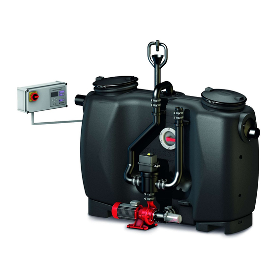
2. Installation Illustration shows NS 2 and NS 15 Inlet Grease storage barrel Outlet Ventilation Sludge trap Cleaning access Grease separation area Control unit Cover with quick release clamp Grease mixing motor / lever Heating dome Rinsing pump Sludge storage barrel Ø... -
Page 7: Installation Instructions
12. The fall / drainage pipes to the inlet of the separator should KESSEL technician for an agreed upon fee. have at least a 1 meter long horizontal run with a slope of at least 1:50 before entering the separator. -
Page 8: Control Unit Mounting
The control unit should be mounted in a frost free area and not in direct sunlight. It should also be placed 2.4 Installation example KESSEL SE M NS 2 Ventilation pipes should be grease separator connected directly to outdoor Sludge trap ambient air (roof). -
Page 9: Placing Separator Into Operating Mode
- Visual inspection - Pressure test The commissioning and initial grease separator training is 3.2 Instructions and hand-over normally handled by a KESSEL customer service represen- tative. 1. The following persons should be present during the grea- se separator commissioning... -
Page 10: Control Unit Settings
4. Operation activated (internally set automated procedures will not start!) 4.1 Control unit settings 0 System info 1 Information The following functions are controlled by the control unit: 4.1.1 General 2 Maintenance - Rinsing (Euro Norm grease separators do not have the rin- 2.1 Manual operation sing function.) 3 Settings... -
Page 11: Disposal Steps
5. Disposal Disposal Steps The aim of re-utilising grease requires frequent waste dis- posal from the grease separator in order to keep the bio- Automatic rinsing is triggered via a time switch. For this rea- Automatic rinsing chemical decomposition process to a minimum. The di- son, leave the valve on the rinsing line (1c) open during nor- scharge of separated material must therefore be carried out mal operation of the grease separator. - Page 12 KESSEL cover. Tips on reducing odour build up 1. When exchanging barrels to it cleanly and quickly.
- Page 13 5. Disposal Exchanging barrels Collection barrel Sludge collection bar- with twist (screwed) rel with operational storage / transport cover (with transpa- covers rent hose and ventila- tion connection) Screwed cover Ventilation connection port Drainage inlet Center of cover for inlet and ventilation Grease collection Operational covers barrel with operatio-...
- Page 14 6. Explosio...
- Page 15 on diagram Lower frame ill. shows NS 2 Pump rinsing system Rinsing system valve Base section of sludge trap Tank seal / gasket Upper section of sludge trap Cover seal Sludge trap cover Quick release clasp Rinsing line hose Rinsing line stub Exchange stub Sludge discharge valve Sludge discharge cover...
- Page 16 7. Control unit Control unit picture / Control unit ID sticker description The control unit ID sticker is located on the right narrow side of the control unit ill. 1 Control unit ID sticker description Control unit type Control unit article number Connection voltage and frequency Current range Protection class (IP)
- Page 17 7. Control unit...
- Page 18 7. Control unit Electrical information: No heating rod Single heating rod 230V single phase, 50 Hz 230V single phase, 50 Hz Twin heating rods 400V 3 - phase, 50 Hz Connection jacks Connection jacks Connection jacks Power supply Mains switch on control unit Mains switch on control unit Mains switch on control unit Connection...
- Page 19 8. Malfunctions and remedial measures The following checks and remedies must be carried out by a licensed professional servicer. If necessary please contact the Follow the safety instructions before carrying out any work on the separator (see Page 2) company that commissioned the separator. Grease separator: Fault Possible cause...
- Page 20 8. Malfunctions and remedial measures Pump: Fault Possible cause Remedial action Pump does not pump any Air in pump Run the disposal pump – after approx 1 mi- fluid nute the pump begins moving fluid again Pump jammed or pump interior area blocked Disconnect control unit from its power source Remove motor’s cover and turn motor shaft If the motor is still jammed, close valve near...
- Page 21 9. Accessories and replacement parts Accessories can normally be installed to the system at a later date. Please contact KESSEL directly. Replacement parts KESSEL offers sampling chambers for indoor free standing Sampling chamber Model Article Nr. Lateral outlet 915 871 installation or for underground installation.
- Page 22 - Condition and watertightness of the separator should be checked 11. Maintenance instructions for SE separators Maintenance instructions for KESSEL ‚SE’ grease sepa- 2.) Check the sludge discharge valve for obstructions, clean rators the inner discharge area and remove any possible block- ages caused by larger objects.
- Page 23 Note: Only the manufacturer may open sealed components or warranted for a period of 24 month. This warranty period be- gins on the day the product is shipped form KESSEL to its cu- screw connections. Otherwise, the warranty may become null stomer.
- Page 25 Separator characteristics...
- Page 26 __________________________________________________________ Planner __________________________________________________________ Address __________________________________________________________ Telephone / Fax __________________________________________________________ Contracted plumbing company __________________________________________________________ Address __________________________________________________________ Telephone / Fax __________________________________________________________ KESSEL-Commissions no.: System operator /owner __________________________________________________________ Address __________________________________________________________ Telephone / Fax __________________________________________________________ User __________________________________________________________ Address __________________________________________________________ Telephone / Fax __________________________________________________________ Person of delivery...
- Page 27 15. Hand-over certificate Handover certificate (copy for the company carrying out the installation) The initial operation and instruction was carried out in the presence of the person authorised to perform the ❏ acceptance and the system operator. The system operator/person authorised to perform the acceptance was informed about the obligation to ser- ❏...
- Page 28 Backwater protection Septic Systems Lifting Stations and pumps Inspection Chambers Drains and shower channels Rainwater Management Systems Separators -Grease Separators -Oil-/ Fuel-/Coalescence Separators -Starch Separators -Sediment Separators...
Need help?
Do you have a question about the SE M NS 2 and is the answer not in the manual?
Questions and answers