Table of Contents
Advertisement
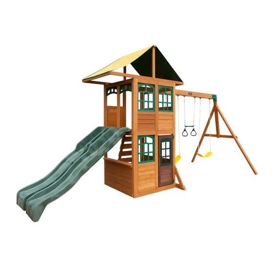
T R E A S U R E C O V E P L AY S Y S T E M – F 2 3 8 6 0
INSTALLATION AND OPERATING INSTRUCTIONS
9.3
30'- 4"
5.6m
18'- 4"
KidKraft, Inc.
4630 Olin Road
Dallas, Texas 75244 USA
customerservice@kidkraft.com
canadacustomerservice@kidkraft.com
1.800.933.0771
972.385.0100
For online parts replacement visit
https://parts.kidkraft.com/
WARNING
and give them to any future owner of this play system. Manufacturer contact information provided below.
OBSTACLE FREE SAFETY ZONE -
MAXIMUM VERTICAL FALL HEIGHT - 6' (1.8 m)
2.3m
8.2m
7'-6"
27'
CAPACITY - 8 Users Maximum, Ages 3 to 10; Weight Limit 110 lbs. (49.9 kg) per child.
RESIDENTIAL HOME USE ONLY. Not intended for public areas such as schools, churches, nurseries, day cares or parks.
WARNING. Only for domestic use.
KidKraft Netherlands BV
Olympisch Stadion 8
1076 DE Amsterdam
The Netherlands
europecustomerservice@kidkraft.com
+31 20 305 8620 M-F from 09:00 to 17:30
(GMT+1)
For online parts replacement visit
https://parts.kidkraft.eu/
To reduce the risk of serious injury or death, you must read and
follow these instructions. Keep and refer to these instructions often
area requires Protective Surfacing. See page 3.
30'4" x 27'(9.3m x 8.2m)
Table of Contents
Warnings And Safe Play Instructions. . . . . . . . . . . . . . . pg. 2
Protective Surfacing Guidelines. . . . . . . . . . . . . . . . . . . pg. 3
Instructions For Proper Maintenance . . . . . . . . . . . . . . . pg. 4
About Our Wood – Limited Warranty . . . . . . . . . . . . . . pg. 5
Keys To Assembly Success . . . . . . . . . . . . . . . . . . . . . . pg. 6
Metric Conversion Sheet . . . . . . . . . . . . . . . . . . . . . . . . pg. 7
Part Id . . . . . . . . . . . . . . . . . . . . . . . . . . . . . . . . . . . . pg. 8-12
Installation of I.D./Warning Plaque . . . . . . . . . . . .Final Step
9403860
10 - 14 Hrs
Two person
assembly
Rev 06-09-2020
Advertisement
Table of Contents

Related Manuals for KidKraft TREASURE COVE


Summary of Contents for KidKraft TREASURE COVE
- Page 1 Protective Surfacing Guidelines....pg. 3 KidKraft, Inc. KidKraft Netherlands BV Instructions for Proper Maintenance ....pg. 4...
- Page 2 Warnings and Safe Play Instructions CONTINUOUS ADULT SUPERVISION REQUIRED. Most serious injuries and deaths on playground equipment have occurred while children were unsupervised! Our products are designed to meet mandatory and voluntary safety standards. Complying with all warnings and recommendations in these instructions will reduce the risk of serious or fatal injury to children using this play system.
- Page 3 Protective Surfacing - Reducing Risk of Serious Head Injury From Falls One of the most important things you can do to reduce the likelihood of serious head injuries is to install shock-absorbing protective surfacing under and around your play equipment. The protective surfacing should be applied to a depth that is suitable for the equipment height in accordance with ASTM F1292.
- Page 4 Instructions for Proper Maintenance Your KidKraft Play System is designed and constructed of quality materials with your child’s safety in mind. As with all outdoor products used by children, it will weather and wear. To maximize the enjoyment, safety and life of your Play Set, it is important that you, the owner, properly maintain it.
- Page 5 About Our Wood KidKraft Premium Play Systems uses only premium playset lumber, ensuring the safest product for your children’s use. Although we take great care in selecting the best quality lumber available, wood is still a product of nature and susceptible to weathering which can change the appearance of your set.
- Page 6 Keys to Assembly Success Tools Required Shovel Measuring Drill (1/8” Safety Hammer Ratchet 1/2”, Level #2 & #3 Phillips Square Step Tape 3/16” Bit) Glasses 7/16” & 9/16” or Robertson Ruler Ladder Key Number: 2X 012 Post 2 x 4 x 83” represent the step number.
- Page 8 Part Identification 1pc. - 2648 - 1 x 4 x 40-5/8 - Floor Board 3632648 1pc. - 2757 LT Post Assembly 1¼ x 2½ x 87" 37632757 8pc. - 2609 - 1 x 5 x 40-5/8" - Floor Board 3632609 2pc.
- Page 9 Part Identification 1pc. - 649A 2pc. - 2756 Short Half Wall - 1.27 x 18.8 x 20-15/16" Siding Assembly 1¼ x 19-15/16 x 39-3/16" 37632649A 37632756 1pc. - 2602 -Upper Jamb 1¼ x 3 x 35-15/16" 3632602 1pc. - 2601 -Lower Jamb 1¼ x 3 x 41-15/16" 3632601 1pc.
- Page 10 Part Identification 1x - Rocks (5pk) 1x - Treasure Cove Bracket Set (3320386) (3203860) 1pc. MOD 3 Pane Transom (2Pk) 3320138 1x - Jamb Mount (4 Pk) (3206302) 1x - Flat Panel Bracket 1x - Hand Grip 1x - Rebar Ground...
- Page 11 Hardware Identification (Actual Size) (5) LW2 - 5/16" Lock Washer - (51303300) (34) TN1 - 1/4" T - Nut (54503200) (5) FW0 - 3/16" Flat Washer - (51103100) (39) LW1 - 1/4" Lock Washer - (51303200) (36) FW1 - 1/4" Flat Washer - (51103200) (10) TN2 - 5/16"...
- Page 12 Hardware Identification (Actual Size) Wafe Bolt 5/16 x 1" Wafer Bolt 5/16 x 3" (3) WB7 - - (53613330) (2) WB1 - - (53613310) 1/4 x 1-3/8" (2) WL3 - Wafer Lag - (52613216) 1/4 x 3" (2) LS3 - Lag Screw - (52213230) 1/4 x 2-1/2"...
- Page 13 Before you discard your cartons fill out the form below. • The carton I.D. stamp is located on the end of each carton. The tracking number is located on the KidKraft ID Plaque (9320374). • Please retain this information for future reference. You will need this information if you contact the Consumer Relations Department.
- Page 14 Step 1: Front and Back Wall Prep Part 1 It is important to assemble the frame on a flat, smooth surface. A: Place (2771) End Post and (2770) End Post Left side by side with the grooves facing up and in. Put (2770) End Post Left on the right hand side.
- Page 15 Step 1: Front and Back Wall Prep Part 2 It is important to assemble the frame on a flat, smooth surface. D: Turn the assembly over, place (2774) Upright in the middle grooves of (2775) Panel Cross Support and (2772) Panel Floor Support then attach all boards with 8 (H9) 1/4 x 1-1/4” Hex Bolts (with lock washer and flat washer) connecting to the previously installed t-nuts.
- Page 16 Step 2: End Wall Prep Part 1 It is important to assemble the frame on a flat, smooth surface. A: Place (2771) End Post and (2770) End Post Left side by side with the grooves facing up and in. (2770) End Post Left on the right hand side.
- Page 17 Step 2: End Wall Prep Part 2 It is important to assemble the frame on a flat, smooth surface. D: Turn the assembly over then attach all boards with 6 (H9) 1/4 x 1-1/4” Hex Bolts (with lock washer and flat washer) connecting to the previously installed t-nuts.
- Page 18 Step 3: Swing Wall Prep Part 1 It is important to assemble the frame on a flat, smooth surface. A: Place (2757) LT Post Assembly and (2758) RT Post Assembly on a hard, flat surface with the notches facing down. The top of the post assemblies have the longer notches. (fig. 3.1) B: Tap 1 (TN2) 5/16”...
- Page 19 Step 3: Swing Wall Prep Part 2 It is important to assemble the frame on a flat, smooth surface. C: Turn the (2757) LT Post Assembly and (2758) RT Post Assembly over and place 2 (2756) Siding Assemblies on top so one sits flush with the top of the middle groove and the second fits flush with the top of the bottom groove.
- Page 20 Step 3: Swing Wall Prep Part 3 It is important to assemble the frame on a flat, smooth surface. E: Attach (2630) SW Top to (2757) LT Post Assembly and (2758) RT Post Assembly with 2 (WB1) 5/16 x 1” Wafer Bolts (with flat washer) connecting to previously installed t-nuts.
- Page 21 Step 3: Swing Wall Prep Part 4 It is important to assemble the frame on a flat, smooth surface. I: Attach the top board in each (2756) Siding Assembly to (2757) LT Post Assembly and (2758) RT Post Assembly with 4 (S30) #8 x 1-1/16” Wood Screws per board. (fig. 3.8 and 3.9) J: Attach the remaining boards in each (2756) Siding Assembly to (2757) LT Post Assembly and (2758) RT Post Assembly with 2 (S0) #8 x 7/8”...
- Page 22 Step 4: Frame Assembly Part 1 It is important to assemble the frame on a flat, smooth surface. A: Place Swing Wall from Step 3 between 2 Front and Back Walls from Step 1, noticing the wall orientations. The tops and bottoms of the walls should be flush. Make sure the walls are square then using the pilot holes as a guide pre-drill with a 3/16”...
- Page 23 Step 4: Frame Assembly Part 2 B: Place End Wall from Step 2 between the Front Wall and Back Wall noticing the wall orientation. The tops and bottoms of the walls should be flush. Make sure the walls are square then using the pilot holes as a guide pre- drill with a 3/16”...
- Page 24 Step 4: Frame Assembly Part 3 C: Loosely attach 1 (2607) Diagonal to left (2778) SW Ground MOD with 1 (H10) 1/4 x 2-1/4” Hex Bolt (with lock washer, flat washer and t-nut). (fig. 4.5) D: Place each (2607) Diagonal tight and flush to the front of the Swing Wall then pre-drill pilot holes with a 3/16” drill bit and attach each (2607) Diagonal to the Swing Wall with 1 (LS3) 1/4 x 3”...
- Page 25 Step 5: Floor Assembly Part 1 A: From inside of the assembly centre (2608) Floor Joist over the pilot holes in both (2768) Panel Floors in the Swing and End Wall, measure 5/8” down from the top of boards then attach (2608) Floor Joist to each board using the left and centre holes with 2 (S4) #8 x 3”...
- Page 26 Step 5: Floor Assembly Part 2 B: On the inside of both the Front and Back Walls place 1 (2777) Side Joist MOD against each (2772) Panel Floor Support, line up bolt holes then loosely attach with 2 (H11) 1/4 x 2-3/4” Hex Bolts (with lock washer, flat washer and t-nut) per joist.
- Page 27 Step 5: Floor Assembly Part 3 C: Fasten each (2777) Side Joist MOD to each (2772) Panel Floor Support with 4 (S3) #8 x 2-1/2” Wood Screws per board as shown in fig. 5.6. D: Tighten all (H11) 1/4 x 2-3/4” Hex Bolts in both (2777) Side Joist MOD. Fig.
- Page 28 Step 5: Floor Assembly Part 4 F: Starting at the Swing Wall place (2648) Floor Board followed by 8 (2609) Floor Boards. Make sure all boards are evenly spaced then attach to (2608) Floor Joist and each (2777) Side Joist MOD with 5 (S20) #8 x 1-3/8” Wood Screws per board.
- Page 29 Step 6: Swing Beam Assembly A: Attach 6 Swing Hangers to the (2614) Engineered Beam using 2 (G7) 5/16 x 5-1/2” Hex Bolts (with 2 flat washers and 1 lock nut) per Swing Hanger as shown in fig. 6.1. B: Flush to the Fort End of (2614) Engineered Beam attach 2 L-Beam Brackets with 2 (G21) 5/16 x 3-3/4” Hex Bolts (with 2 flat washers and 1 lock nut).
- Page 30 Step 7: Swing End Assembly A: Loosely attach 2 (2613) Heavy SW Posts to (2615) SW Upright using 2 (G7) 5/16 x 5-1/2” Hex Bolts (with lock washer, flat washer and t-nut). Notice 2 bolt holes at top of (2615) SW Upright and orientation of angle. (fig.
- Page 31 Step 8: Attach Swing End to Swing Beam A: Place Swing End Assembly against Swing Beam Assembly then place 1 Beam Bracket on each side of the assembly (they are specific for left and right side) and attach with 5 (G21) 5/16 x 3-3/4” Hex Bolts (with 2 flat washers and 1 lock nut).
- Page 32 Step 9: Attach Swing Assembly To Fort A: Place Swing Assembly against top of (2630) SW Top, make sure assembly is level then attach from inside the fort assembly into each L-Beam Bracket with 4 (G8) 5/16 x 2” Hex Bolts (with 2 flat washers and 1 lock nut).
- Page 33 Step 10: Install Ground Stakes MOVE FORT TO FINAL LOCATION PRIOR TO STAKING FINAL LOCATION MUST BE LEVEL GROUND A: In the 5 places shown in fig. 10.1 drive the Rebar Ground Stakes 13” into the ground against outside front corner of the End Wall, on both (2607) Diagonals and both (2613) Heavy SW Posts.
- Page 34 Step 11: Install Upper and Lower Jambs A: In the upper opening of the End Wall place 1 (2602) Upper Jamb so it measures 17” to the inside of each post then attach with 2 Jamb Mounts using 4 (S0) #8 x 7/8” Truss Screws per mount. (fig. 11.1, 11.3, 11.4 and 11.5) B: In the lower opening of the Front Wall place 1 (2601) Lower Jamb so it measures 17”...
- Page 35 Step 12: Install Window and Wall Inserts A: On the Front Wall, in the places shown in fig. 12.1, install 2 (2655) Upper Window Inserts in the upper opening and 1 (2649) Lower Window Insert in the lower opening using 9 (S0) #8 x 7/8” Truss Screws per insert. (fig. 12.1, 12.2 and 12.3) B: On the End Wall, in the places shown in fig.
- Page 36 Step 13: Rock Wall Assembly Fig. 13.1 Note: The holes in the rock boards 2776 must orient to the 2780 2780 2781 top of the boards. 2781 2781 2779 7-5/8” Approx x 4 per board Note: Gaps between boards 2-1/4”, not to exceed 2-3/8” Fig.
- Page 37 Step 14: Attach Rock Wall Assembly to Fort Part 1 A: Place Rock Wall Assembly centred in opening of the Back Wall and flush as shown below. Attach (2776) Rock Rails to the Front Wall using 4 (S11) #8 x 2” Wood Screws. (fig. 14.1 and 14.2) B: Attach 1 (2779) Access Board to top of Rock Wall Assembly, flush to top of (2776) Rock Rails using 4 (S20) #8 x 1-3/8”...
- Page 38 Step 14: Attach Rock Wall Assembly to Fort Part 2 C: Drive 1 Rebar Ground Stake 13” into the ground against outside (2776) Rock Rail then attach with 1 (S7) #12 x 2” Pan Screw. Be careful not to hit the washer while hammering stake into the ground as this could cause the washer to break off.
- Page 39 Step 15: Attach Hand Grip to Fort A: Measure 6” from the top of the floor boards on the left hand side of the Rock Board, pre-drill with a 1/8” drill bit then attach 1 Hand Grip with 2 (WL3) 1/4 x 1-3/8” Wafer Lags to the Front Wall. (fig. 15.1) Hand Grip Fig.
- Page 40 Step 16: Cafe Table Assembly A: Place (2612) Table Support flush to the notched out ends of (2611) Table Top and attach with 4 (S7) #12 x 2” Pan Screws as shown in fig. 16.1. B: Place Table Top Assembly tight in the opening of End Wall with the overhang on the outside of the assembly as shown in fig.
- Page 41 Step 17: Attach Door Components Part 1 A: On the inside of (2709) Door Window Panel measure 15” up from the bottom and attach Catch Plate flush to the edge using 2 (S18) #6 x 1” Wood Screws. (fig. 17.1) B: On the inside of (2709) Door Window Panel measure 22”...
- Page 42 Step 17: Attach Door Components Part 2 C: On the outside of the (2709) Door Window Panel attach the second Door Handle at approximately the same place as the one on the inside. Use 2 (S13) #6 x 5/8” Pan Screws. (fig. 17.2) D: On the opposite side of the Door Handle measure 5/8”...
- Page 43 Step 18: Attach Door Assembly to Fort A: On the Front Wall measure 5/8” up from the top of (2769) Panel BT Frame and a maximum 5/8” from the inside edge of (2771) End Post then attach the remaining side of the hinges to (2771) End Post using 3 (S13) #6 x 5/8”...
- Page 44 Step 19: Attach Door Stop A: In the notched out opening of (2715) Door Stop attach the Magnetic Catch using 2 (S18) #6 x 1” Wood Screws. (fig. 19.1) Important: Use a hand held screw driver and DO NOT over tighten. B: On the inside of the assembly, attach (2715) Door Stop to (2601) Lower Jamb with 3 (S11) #8 x 2”...
- Page 45 Step 20: Attach Slide to Fort A: Place 1 Slide in the centre of each opening of the End Wall, pre-drill with a 1/8” drill bit then attach each slide to fort through the (2772) Panel Floor Support using 3 (S7) #12 x 2” Pan Screws per slide. (fig. 20.1, 20.2 and 20.3) Fig.
- Page 46 Step 21: Attach Swings A: Attach 1 Threaded Clip to each Acro Rope and the Acro Bar. Attach another Threaded Clip to each Acro Handle and join with first Threaded Clip. Make sure to close the Threaded Clip tightly using an adjustable wrench.
- Page 47 Step 22: Attach Tarp Frame Part 1 A: On the Front and Back Walls place 1 (2786) Roof Side on top of each (2775) Panel Cross Support so the extension on the Swing Wall measures 9-1/4” and the extension on the End Wall measures 18-1/8” then attach with 4 (S4) #8 x 3”...
- Page 48 Step 22: Attach Tarp Frame Part 2 D: Attach each (2786) Roof Side to each (2775) Panel Cross Support with 2 Flat Panel Brackets per side using 4 (S8) #12 x 3/4” Pan Screws per bracket. (fig. 22.3 and 22.4) Fig.
- Page 49 Step 22: Attach Tarp Frame Part 3 E: Place (2787) Roof Top on each (2785) Roof Upright so the ends measure 1-1/4” overhang on each side then attach using 2 (S4) #8 x 3” Wood Screws per end. (fig. 22.5 & 22.6) F: Pre-drill pilot holes for the screws using a 1/8”...
- Page 50 Step 23: Attach Canopy A: Place Canopy over (2787) Roof Top making sure bottom edges of Canopy are even on both sides of assembly. (fig. 23.1) B: Secure one side by attaching Canopy to 1 (2784) Roof End using 5 (S5) #8 x 1/2” Pan Screws (with #8 flat washer).
- Page 51 POUR LES ENFANTS DE 3 À 10 ANS D'ÂGE; limite de 110 Livres par enfant. Nombre maximum d’ utilisateurs, installation et d'utilisation; d'autres informations sont disponibles sur: www.KidKraft.com Contact us at: KidKraft Dallas, TX 75244 USA 1-800-933-0771 Tracking Number: Número de Numèro de Suivi:...
- Page 52 NOTES NOTES...
- Page 53 NOTES NOTES...
- Page 54 Would you recommend the purchase of our products to friends and family? Comments: MAIL TO: Fill out your registration card online at KidKraft https://prdregistration.kidkraft.com/ 4630 Olin Road Dallas, TX 75244 United States KidKraft would like to say Thank You for Attention: Customer Service your time and feedback.
Need help?
Do you have a question about the TREASURE COVE and is the answer not in the manual?
Questions and answers