Siemens SIMATIC IPC547J Operating Instructions Manual
Hide thumbs
Also See for SIMATIC IPC547J:
- Quick install manual (2 pages) ,
- Manual (26 pages) ,
- Manual (62 pages)
Table of Contents
Advertisement
SIMATIC
Industrial PC
SIMATIC IPC547J
Operating Instructions
01/2021
A5E43920357-AA
Preface
Product description
Safety instructions
Installing and connecting
the device
Commissioning the device
Operating the device
Expanding and assigning
parameters to the device
Device maintenance and
repair
Technical specifications
Dimension drawings
Standards and approvals
Hardware description
Technical support
Markings and symbols
1
2
3
4
5
6
7
8
9
10
A
B
C
Advertisement
Table of Contents

Subscribe to Our Youtube Channel
Related Manuals for Siemens SIMATIC IPC547J


Summary of Contents for Siemens SIMATIC IPC547J
- Page 1 Preface Product description SIMATIC Safety instructions Installing and connecting the device Industrial PC SIMATIC IPC547J Commissioning the device Operating the device Operating Instructions Expanding and assigning parameters to the device Device maintenance and repair Technical specifications Dimension drawings Standards and approvals...
- Page 2 Note the following: WARNING Siemens products may only be used for the applications described in the catalog and in the relevant technical documentation. If products and components from other manufacturers are used, these must be recommended or approved by Siemens. Proper transport, storage, installation, assembly, commissioning, operation and maintenance are required to ensure that the products operate safely and without any problems.
-
Page 3: Preface
General knowledge in the field automation control engineering is recommended. Range of validity of these operating instructions These operating instructions are valid for all order versions of the SIMATIC IPC547J. History Currently released versions of these operating instructions:... - Page 4 Siemens' products and solutions undergo continuous development to make them more secure. Siemens strongly recommends that product updates are applied as soon as they are available and that the latest product versions are used. Use of product versions that are no longer supported, and failure to apply the latest updates may increase customers' exposure to cyber threats.
-
Page 5: Table Of Contents
Table of contents Preface ..............................3 Product description ..........................11 Important instructions and manuals for operating the device..........11 Product highlights......................13 Scope of application ......................15 External design of the device ..................... 16 1.4.1 Front panel ........................16 1.4.2 Drive cage type A ....................... - Page 6 Table of contents 3.2.2 Securing device ......................... 56 Connecting the device ....................... 58 3.3.1 Country-specific information on supply voltage ..............58 3.3.2 Connection of equipotential bonding line................59 3.3.3 Connecting the power supply .................... 59 3.3.3.1 Connect single power supply (AC) ..................59 3.3.3.2 Connecting a redundant power supply (AC) ...............
- Page 7 Table of contents Remote maintenance of the device ..................85 5.6.1 Remote maintenance functions and device requirements for remote maintenance ..... 85 5.6.2 Remote maintenance with iAMT ..................86 5.6.2.1 Enable Intel® AMT control on the device ................86 5.6.2.2 Activate Intel®...
- Page 8 Table of contents Removing and installing hardware ................... 130 7.3.1 Front fan maintenance ....................130 7.3.1.1 Removing the fan cover from the front fan ............... 130 7.3.1.2 Change the filter pad of the front fan ................130 7.3.1.3 Changing the front fan ....................131 7.3.2 Change the fan on drive cage type A ................
- Page 9 Table of contents Standards and approvals ........................167 10.1 Certificates and approvals ....................167 10.1.1 ISO 9001 certificate ......................167 10.1.2 Software license agreements ................... 167 10.1.3 UL approval ........................167 10.1.4 FCC Rules (USA) ....................... 167 10.1.5 ICES Compliance (Canada) ....................168 10.1.6 RCM (Australia / New Zealand) ..................
- Page 10 Table of contents Operating Instructions, 01/2021, A5E43920357-AA...
-
Page 11: Product Description
Supplied in printed form with the device • Link and QR code to the online form for the quality control • Supplied data storage medium notification in the SIEMENS After Sales Information System (ASIS) • Operating Instructions of the device • Installation of the device •... - Page 12 • Supplied data storage medium • Temperature monitoring • Online at: • Fan monitoring SIMATIC IPC DiagBase • Monitoring drives (https://support.industry.siemens. com/cs/ww/en/view/109749690) • Watchdog • Operating hours counter • Battery monitoring SIMATIC IPC Monitoring functions such as with • Online at:...
-
Page 13: Product Highlights
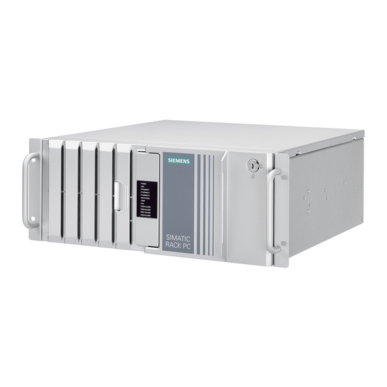
Product description 1.2 Product highlights Product highlights The SIMATIC IPC547J is a high-performance industrial PC in 19" installation format (4 HM). It is perfectly suited for high-performance industrial PC applications. Device view Note Depending on the configuration ordered the features and illustrations described in this manual may differ from the features of your device. - Page 14 Product description 1.2 Product highlights High productivity through fast data processing • 10th generation Intel® processors: Xeon, Core i9, Core i7, Core i5 or Core i3 up to 10 cores / 20 threads • Graphics controller (630) integrated in the CPU up to 4K Ultra HD resolution •...
-
Page 15: Scope Of Application
Product description 1.3 Scope of application Time savings due to high flexibility in commissioning, use and service • High expandability through integrated interfaces: – 3 x Intel® Gbit Ethernet – 2 x USB 3.1 Gen 1 (Front) – 4 x USB 3.1 Gen 2 (rear of device): 2 x Type A and 2 x Type C –... -
Page 16: External Design Of The Device
Product description 1.4 External design of the device External design of the device 1.4.1 Front panel Front: Front door is closed ① 19" mounting bracket with handle ② Fan cover of front fan with openings for ventilation of the device (locked by front door) ③... - Page 17 Product description 1.4 External design of the device Front: Front door is open ① Locking screw of the enclosure cover ② On-off button, see Operator controls (Page 28) ③ Rese pushbutton, see Operator controls (Page 28) ④ Drive cage (in this case type A); depending on the expansion variant, see: •...
-
Page 18: Drive Cage Type A
Product description 1.4 External design of the device 1.4.2 Drive cage type A Drives and mounting locations in the drive cage type A The drive cage type A can only be installed in devices with a standard enclosure and is located behind the front door. - Page 19 Product description 1.4 External design of the device Components of the removable tray Status display (Page 33) Status display (Page 33) Number of the mounting location (here: Mounting location 0) Lock See also Installation conditions for drives in drive cage type A (Page 105) Operating Instructions, 01/2021, A5E43920357-AA...
-
Page 20: Drive Cage Type B
Product description 1.4 External design of the device 1.4.3 Drive cage type B Drives and mounting locations in the drive cage type B The drive cage type B can only be installed in devices with a standard enclosure and is located behind the front door. -
Page 21: Type C Drive Holder
Product description 1.4 External design of the device 1.4.4 Type C drive holder Drives and mounting locations in the drive cage type C The drive cage type C can only be installed in devices with a short enclosure and is located behind the front door. - Page 22 Product description 1.4 External design of the device Numbering of mounting locations Mounting location 0 Mounting location 1 See also Installation conditions for drives in the drive cage type C (Page 125) Safety instructions on device and system extensions (Page 48) Open the device (Page 93) Switching off the device (Page 72) Operating Instructions, 01/2021, A5E43920357-AA...
-
Page 23: Rear Of The Device
Product description 1.4 External design of the device 1.4.5 Rear of the device ① Connection for functional earthing, see "Connection of equipotential bonding line (Page 59)" ② COM2 (optional) ③ Holes for attaching the retainer for the internal USB stick ④... -
Page 24: Connections
Product description 1.4 External design of the device 1.4.6 Connections 1.4.6.1 Device ports Connections on the front of the device There are two USB connection sockets on the front of the device behind the front panel. Note the technical specifications of the interfaces (Page 158). Connection socket ①... - Page 25 Product description 1.4 External design of the device Connections on the rear of the device with SMS-H410 motherboard Note the technical specifications of the interfaces (Page 158). No. Connection socket ① COM1 (X30) ② LAN 2 (X2 P1) Intel® Jacksonville I219-V ③...
- Page 26 Product description 1.4 External design of the device Connections on the rear of the device with SMS-W480 motherboard Note the technical specifications of the interfaces (Page 158). No. Connection socket ① COM1 (X30) ② LAN 3 (X3 P1) Intel® Springville i210-AT ③...
- Page 27 Product description 1.4 External design of the device No. Connection socket ⑧ USB 3.1 Gen 2; Type C backwards compatible to USB 3.0 / 2.0 / 1.1; each 1500 mA / high current • (X63) ⑨ USB 3.1 Gen 2; Type A SuperSpeed;...
-
Page 28: Power Supply Connections
Product description 1.4 External design of the device 1.4.6.2 Power supply connections Sockets for power plugs with single and redundant power supply Single power supply Redundant power supply 1.4.7 Operator controls WARNING Risk of electric shock The buttons and switches described in the following do not fully disconnect the device from the line voltage. - Page 29 Product description 1.4 External design of the device On-off switch with single and redundant power supply The following figures show the location of the on/off switch on the rear of the device for devices with simple or redundant power supply. Single power supply Redundant power supply ①...
- Page 30 Product description 1.4 External design of the device Alarm reset button (redundant power supply) The alarm reset button is only available for devices with redundant power supply. Use the alarm reset button to switch off the signal tone of the redundant power supply in the event of an error.
-
Page 31: Status Displays
Product description 1.4 External design of the device 1.4.8 Status displays 1.4.8.1 System status displays The status displays for the system are located on the front of the device. They provide information on the status of the device components. Status display Meaning Status Meaning of the status... -
Page 32: Status Display Of The Ethernet Interface
Product description 1.4 External design of the device ⑧ Fan status No error Possible causes: • Front fan faulty • The fan on the processor heat sink is faulty • Fan on drive cage type A faulty • Fan of simple power supply faulty (non- redundant power supply) ⑨... -
Page 33: Status Display Of Redundant Power Supply
Product description 1.4 External design of the device 1.4.8.3 Status display of redundant power supply Status display Meaning Status Meaning of the status • Module is out of service, no redundancy in Power supply module Status of the power supply module effect. -
Page 34: Internal Construction Of The Device
Product description 1.5 Internal construction of the device Internal construction of the device ① Power supply, single or redundant (here in the example: Single power supply) ② Heat sink of the processor ③ Rod with card holders for expansion cards ④... -
Page 35: Accessories And Spare Parts
Accessories and spare parts 1.6.1 Hardware accessories Accessories from Siemens are available for your device. These are not included in the scope of delivery. Obtaining accessories from the SIEMENS Industry Mall You can find additional information in the online ordering system Industry Mall (https://mall.industry.siemens.com). - Page 36 Product description 1.6 Accessories and spare parts Name Description Article number Adapter: DP to VGA adapter 6ES7648-3AG00-0XA0 DisplayPort to VGA for onboard interfaces Adapter: Connection of dual-head adapter to the optional graphics card possible with the following adapters: Mini DisplayPort 6ES7648-3AL00-0XA0 •...
- Page 37 Product description 1.6 Accessories and spare parts SIEMENS spare parts services Information on ordering, the provision and delivery of spare parts can be found under "Industry Online Support: Spare parts services (http://support.automation.siemens.com/WW/view/en/16611927)". Name Description Article number Rack PC 4HM filter set...
-
Page 38: Software Accessories
IPCs, communication with other systems, worldwide alerts and creation of custom monitoring applications. Further information on the software products and references to the online catalog and ordering system (Industry Mall (https://mall.industry.siemens.com)) can be found on the SIMATIC IPC software (http://www.automation.siemens.com/mcms/pc-based- automation/en/industrial-pc/expansion_components_accessories) homepage. -
Page 39: Safety Instructions
Safety instructions General safety instructions Danger if work is performed incorrectly WARNING The installer of the system is responsible for the safety of a system in which the device is integrated. There is a risk of malfunction if work on the device is carried out incorrectly, if the device is faulty, or if it is integrated incorrectly into a system. - Page 40 Safety instructions 2.1 General safety instructions Risk of electric shock when working on the device WARNING Risk of electric shock from mains voltage The on/off button and on/off switch do not fully disconnect the device from the mains. There is also a risk of fire if the device or connecting lines are damaged. •...
- Page 41 Safety instructions 2.1 General safety instructions Danger when working on electrostatically sensitive components (ESD) Electrostatic sensitive devices can be labeled with an appropriate symbol. NOTICE Electrostatic sensitive devices (ESD) The device contains electrostatically sensitive components that can be destroyed by voltages that are far below human perception.
-
Page 42: Safety Instructions On Transport And Storage
Safety instructions 2.2 Safety instructions on transport and storage Safety instructions on transport and storage Danger when carrying and lifting the device CAUTION Risk of physical injury The device is heavy and may injure persons and be damaged if it falls. •... -
Page 43: Safety Instructions For Assembly
Safety instructions 2.3 Safety instructions for assembly Risk due to condensation NOTICE Damage from condensation If the device is subjected to low temperatures or extreme fluctuations in temperature during transportation, moisture could occur on or inside the HMI device (condensation). Moisture can cause a short-circuit in electrical circuits and damage the device. - Page 44 Safety instructions 2.3 Safety instructions for assembly Important notes on rack assembly Note • Higher operating temperature If installed in a closed unit or a multi-unit rack, the ambient operating temperature may be greater than the room temperature. Install the device in an environment recommended by the manufacturer, see notes under "Climatic and mechanical and ambient conditions (Page 150)"...
-
Page 45: Safety Instructions On Ambient And Environmental Conditions
Safety instructions 2.4 Safety instructions on ambient and environmental conditions Safety instructions on ambient and environmental conditions Approvals expire if the instructions are not observed WARNING Approvals expire if the instructions are not observed If the ambient and environmental conditions are not observed when installing and operating the device or the system, the approvals according to IEC/EN/UL/CSA 61010-2-201 will become void. - Page 46 Safety instructions 2.4 Safety instructions on ambient and environmental conditions Notes on the suitable location of the device Note When you plan your project, you should make allowances for: • Operate the device only in closed rooms. • Install the device in such a way that it poses no danger, e.g. by falling over. •...
-
Page 47: Safety Instructions For I/O Devices
Safety instructions 2.5 Safety instructions for I/O devices Safety instructions for I/O devices Risk of damage to the device from connecting I/O devices CAUTION Fault caused by I/O devices The connection of I/O devices can cause faults in the device. The result may be personal injury and damage to the machine or plant. -
Page 48: Safety Instructions On Device And System Extensions
Safety instructions 2.6 Safety instructions on device and system extensions Risk of electric shock from mains voltage WARNING Risk of electric shock The on/off button and on/off switch do not fully disconnect the device from the mains. There is also a risk of fire if the device or connecting lines are damaged. •... - Page 49 Safety instructions 2.6 Safety instructions on device and system extensions Risk of electric shock when working on the device WARNING Risk of electric shock from mains voltage The on/off button and on/off switch do not fully disconnect the device from the mains. There is also a risk of fire if the device or connecting lines are damaged.
- Page 50 Safety instructions 2.6 Safety instructions on device and system extensions Danger from unauthorized or improperly performed repairs WARNING Danger due to unauthorized opening or improperly carried out repairs or extensions Improperly carried out repairs or extensions to the device can lead to property damage or danger to the users.
-
Page 51: Installing And Connecting The Device
On the supplied data storage medium (read only) you will find: • Software and tools to recover your ordered Microsoft® Windows® operating system • Device drivers for installation in operating systems • Quick Install Guide SIMATIC IPC547J • SIMATIC IPC547J operating instructions • Product information •... -
Page 52: Checking The Delivery Package
(Page 38) Printed documents • Quick Install Guide SIMATIC IPC547J with link and QR code to the online form for quality control (quality control notification) in the SIEMENS After Sales Information System (ASIS) • Product Information "Important notes on your device"... -
Page 53: Device Identification Data
If the contents of the package are incomplete, damaged or do not correspond to your order, you can use the After Sales Information System (ASIS) (http://siemens.com/asis) to provide feedback on product deliveries and repairs. Complete the online form for quality control (quality control notification). -
Page 54: Mounting The Device
Installing and connecting the device 3.2 Mounting the device COA label The COA label (Certificate of Authenticity) is located inside the front door. Note The COA label is only available for devices delivered with Microsoft® Windows® operating system installed. Example: COA label for the Microsoft® Windows® 10 operating system (the data of the product key are grayed out in the figure) See also Important instructions and manuals for operating the device (Page 11) - Page 55 Installing and connecting the device 3.2 Mounting the device Installation in the control cabinet When installing the device in a control cabinet, use a central and easily accessible AC circuit breaker as close as possible to the device. Horizontal: Mounting on device base This installation type meets the requirements in accordance with IEC60297-3-100.
-
Page 56: Securing Device
Installing and connecting the device 3.2 Mounting the device 3.2.2 Securing device WARNING Dangerous voltage and fire hazard Improper actions during installation and assembly may lead to personal injury and/or substantial damage to equipment. It is essential that you follow the installation and assembly instructions under: •... - Page 57 Installing and connecting the device 3.2 Mounting the device Bore holes for telescopic rails Holes for standard enclosure Holes for short enclosure The dimensions for the holes can be found under: "Dimension drawing of the telescope rails (Page 165)". Detailed information on the drives can be found under: "Technical specifications of the telescopic rails (Page 159)".
-
Page 58: Connecting The Device
Installing and connecting the device 3.3 Connecting the device Connecting the device 3.3.1 Country-specific information on supply voltage Country-specific information on supply voltage for USA and Canada Supply voltage 120 V / 230 V / 240 V Ensure that the power cords used are rated for the maximum current input and ambient temperature of the device and meet the requirements of the following standards: •... -
Page 59: Connection Of Equipotential Bonding Line
Installing and connecting the device 3.3 Connecting the device 3.3.2 Connection of equipotential bonding line A low-impedance earth connection ensures that interference signals generated by external power supply cables, signal cables or other cables to the I/O devices are safely discharged to earth. - Page 60 Installing and connecting the device 3.3 Connecting the device WARNING Risk of electric shock The on/off button and on/off switch do not fully disconnect the device from the mains. There is also a risk of fire if the device or connecting lines are damaged. •...
-
Page 61: Connecting A Redundant Power Supply (Ac)
Installing and connecting the device 3.3 Connecting the device 3.3.3.2 Connecting a redundant power supply (AC) WARNING Injury to persons or damage to property when operated on an incorrect power supply system If you connect the device to an unsuitable power supply, the device receives voltages and currents that are too high or too low. - Page 62 Installing and connecting the device 3.3 Connecting the device 4. Switch the device on using the on/off switch (position |). The status display on the power supply modules light up green. Note If only one of the power supply modules works, a warning signal sounds. You turn off the warning signal by pressing the alarm reset button on the working power supply module.
-
Page 63: Connecting I/O Devices
Installing and connecting the device 3.3 Connecting the device 3.3.4 Connecting I/O devices 3.3.4.1 Connecting external devices CAUTION Fault caused by I/O devices The improper connection of I/O devices can cause faults in the device. The result may be personal injury and damage to the machine or plant. Be sure to follow the Instructions for connecting I/O devices (Page 47). -
Page 64: Connecting Several Monitors (Multi-Monitoring)
Installing and connecting the device 3.3 Connecting the device 3.3.4.3 Connecting several monitors (multi-monitoring) Connection of monitors for devices with SMS-H410 motherboard and optional P400 graphics card For connecting monitors to the internal graphics card, there are 2 connection sockets on the rear of the device as standard. - Page 65 Installing and connecting the device 3.3 Connecting the device Connection of monitors for devices with SMS-W480 motherboard and optional P400 graphics card For connecting monitors to the internal graphics card, there are 3 connection sockets on the rear of the device as standard. •...
- Page 66 Installing and connecting the device 3.3 Connecting the device Connection of monitors for devices with SMS-W480 motherboard and optional P2200 graphics card For connecting monitors to the internal graphics card, there are 3 connection sockets on the rear of the device as standard. •...
- Page 67 Installing and connecting the device 3.3 Connecting the device Connection socket on Connection socket on the Connection socket on the optional P2200 graphics card monitor internal graphics card DVI-D (DisplayPort) (DisplayPort) (DisplayPort) (DPP1; (DPP2; (X70) (DisplayPort) X71) X72) Monitor 7 (DisplayPort) via adapter, see "Hardware accessories"...
-
Page 68: Connecting The Device To Networks
Use this software package to create, operate and configure an innovative network for Field & Control level. Additional information is available under SIMATIC NET (http://w3.siemens.com/mcms/automation/en/industrial- communications/Pages/Default.aspx). The software package and the documentation are not included in the scope of delivery... - Page 69 Installing and connecting the device 3.3 Connecting the device Procedure 1. Connect I/O devices to the corresponding sockets on the rear of the device. Information on the position of the sockets is available in "Device ports (Page 24)". 2. Screw the desired strain relief ① with the fixing screw ② on the left and/or right of the device.
- Page 70 Installing and connecting the device 3.3 Connecting the device Operating Instructions, 01/2021, A5E43920357-AA...
-
Page 71: Commissioning The Device
Commissioning the device Switching on the device Requirement • The power supply is connected. (Page 59) Procedure 1. Switch the on/off switch (in case of redundant power supply: both on/off switches) on the rear of the device (position | ). 2. -
Page 72: Switching Off The Device
Commissioning the device 4.3 Switching off the device Switching off the device Shutting down the operating system For active operating system: • Shut down the operating system properly. For inactive operating system • Briefly press the on/off button. Information on the position of the button is available under "Operator controls (Page 28)". - Page 73 Commissioning the device 4.3 Switching off the device Hardware reset If the device does not respond to input from the keyboard or mouse, restart it with the hardware reset. A started operating system will not hereby shut down safely. NOTICE Data loss With a hardware reset, the device is switched off and restarted.
- Page 74 Commissioning the device 4.3 Switching off the device Operating Instructions, 01/2021, A5E43920357-AA...
-
Page 75: Operating The Device
Operating the device Opening the front door Procedure 1. Open the front door with the key. 2. Pull the front door to the side. Multi-monitoring In its delivery state, the device is equipped with a graphics card. To connect several monitors to the device at the same time (Page 64)(multi-monitoring), you can install an additional, so- called "optional graphics card"... -
Page 76: Drive Configurations
Operating the device 5.3 Drive configurations Drive configurations 5.3.1 RAID systems 5.3.1.1 RAID1 system An RAID1 system works on the principle of "data mirroring on two drives". In the event of a defective drive the RAID1 system can continue to work on the remaining drive and thus achieves a high level of availability. -
Page 77: Hot-Spare Drive In Raid1 Or Raid5 Systems
Operating the device 5.4 Onboard RAID system 5.3.1.3 Hot-spare drive in RAID1 or RAID5 systems A hot spare drive is a drive included in the device as spare. If you have ordered a device with a hot-spare drive, your device is equipped with this hot- spare drive in the factory state. -
Page 78: Onboard Raid1 System: Installation Options For Drives
Operating the device 5.4 Onboard RAID system 5.4.2 Onboard RAID1 system: Installation options for drives The 2 hard disks required for an onboard RAID1 system may be installed at the following locations: • Drive cage type A (Page 105) • Drive cage type B (Page 115) 5.4.3 Onboard RAID5 system: Installation options for drives The hard disks required for an onboard RAID5 system may be installed at the following... -
Page 79: Monitoring The Onboard Raid System With "Intel® Rapid Storage Technology
Operating the device 5.4 Onboard RAID system 3. From the firmware selection menu, using the arrow keys, select the entry "Intel <R> Rapid Storage Technology" and confirm your selection. 4. Select "Create RAID Volume". 5. In the next window, enter a name for the RAID system. 6. -
Page 80: Integrating A New Drive Into An Onboard Raid System
Operating the device 5.4 Onboard RAID system Display status of the onboard RAID system (faulty drive) 1. Select the "Status" tab. In the "Storage System View" area on the right side of the window, you will find information on: – a defective drive –... - Page 81 Operating the device 5.4 Onboard RAID system Configure "Automatic integration of a new drive" (before replacing a defective drive) NOTICE Risk of data loss If a new drive is automatically integrated, the new drive is not checked for partition information or existing data. All partitions and data of the new drive are deleted without warning.
-
Page 82: Integrating A Hot-Spare Drive Into An Onboard Raid System
Operating the device 5.4 Onboard RAID system 5.4.4.4 Integrating a hot-spare drive into an onboard RAID system The onboard RAID system is configured in the delivery state in such a way that a new hot- spare drive is automatically integrated. If the automatic integration of a drive in the onboard RAID system has been deactivated (Page 80)or the hot spare drive has been replaced in an onboard RAID system, then you must integrate the new drive manually. -
Page 83: Monitoring Of The Device
Operating the device 5.5 Monitoring of the device Monitoring of the device 5.5.1 Monitoring functions You can monitor the following device functions with the SIMATIC DiagBase or SIMATIC DiagMonitor software: Monitoring Description Status display and actions Temperature • Monitoring of high and low temperature limits and •... -
Page 84: Simatic Ipc Diagbase
Operating the device 5.5 Monitoring of the device Software for device monitoring You can find information on the monitoring software and its documentation under: • SIMATIC IPC DiagBase (Page 84) for monitoring and alarm output locally on the device • SIMATIC IPC DiagMonitor (Page 84) for monitoring and alarm output via the network SIMATIC DiagBase or SIMATIC DiagMonitor also controls the status displays of the IPC, see: System status displays (Page 31). -
Page 85: Remote Maintenance Of The Device
Operating the device 5.6 Remote maintenance of the device Remote maintenance of the device 5.6.1 Remote maintenance functions and device requirements for remote maintenance Remote maintenance of the devices is performed using Intel® Active Management Technology (iAMT), which is integrated into the hardware and firmware of the computer. Through remote access to SIMATIC IPCs, system or program errors can be eliminated, program updates can be performed and firmware/BIOS settings can be made from a control room (without on-site presence). -
Page 86: Remote Maintenance With Iamt
Operating the device 5.6 Remote maintenance of the device 5.6.2 Remote maintenance with iAMT 5.6.2.1 Enable Intel® AMT control on the device To make use of "Intel® Active Management Technology ", proceed as follows: • Note the information on the device requirements for Intel® AMT. (Page 85) •... -
Page 87: Configuring Intel® Amt
Operating the device 5.6 Remote maintenance of the device 5.6.2.3 Configuring Intel® AMT Requirements and procedure for using Intel® AMT Requirement • The Intel® AMT functions are enabled. (Page 86) • The device was switched off or restarted after activating the Intel® AMT functions. Procedure 1. - Page 88 Operating the device 5.6 Remote maintenance of the device Options of the MEBx Use "Intel® Management Engine BIOS Extension" (MEBx) to configure important firmware settings of your device to use Intel® AMT functions and the Intel® Management Engine (ME). The following options are available for Intel® AMT-enabled devices: •...
- Page 89 Operating the device 5.6 Remote maintenance of the device MEBx setting Meaning User Consent User Consent settings. (only if "Manageability Feature Forces the following additional security behavior: Selection" = Enabled) When a user attempts to establish a KVM connection remotely, a six-digit number is displayed on the AMT PC.
-
Page 90: Reset Intel® Amt Functions To Default Settings And Disabling Iamt
Operating the device 5.6 Remote maintenance of the device 5.6.2.4 Reset Intel® AMT functions to default settings and disabling iAMT One effect of resetting to the default settings is that Intel® AMT is disabled. 1. Switch on the device or restart it. 2. -
Page 91: Disabling Intel® Amt Access To The Firmware/Bios Settings
Operating the device 5.6 Remote maintenance of the device 5.6.2.5 Disabling Intel® AMT access to the firmware/BIOS settings You can prevent access to firmware/BIOS settings with Intel® AMT This may be necessary, for example, in the following cases: • When you are no longer using Intel® AMT. •... -
Page 92: Trusted Platform Module (Tpm)
Operating the device 5.7 Trusted Platform Module (TPM) Trusted Platform Module (TPM) Depending on the ordered configuration of your device, a Trusted Platform Module according to Standard TPM V2.0 may be available. The Trusted Platform Module is a chip that enhances your device with security functions. -
Page 93: Expanding And Assigning Parameters To The Device
Expanding and assigning parameters to the device Open the device Requirement • You know the important safety instructions under "Safety instructions on device and system extensions (Page 48)". • T10 screwdriver Procedure 1. Fully disconnect the device from the line voltage, see "Switching off the device (Page 72)". 2. -
Page 94: Installing And Removing Expansion Cards
Expanding and assigning parameters to the device 6.2 Installing and removing expansion cards Installing and removing expansion cards 6.2.1 Information on using expansion cards Slots for expansion cards You can find information on which expansion card you can install in a given slot under "Technical specifications of the expansion card slots (Page 153)". -
Page 95: Installing Expansion Cards
Expanding and assigning parameters to the device 6.2 Installing and removing expansion cards 6.2.2 Installing expansion cards Requirement • You know the important safety instructions under "Safety instructions on device and system extensions (Page 48)". • You know the Information on using expansion cards. (Page 94) Procedure 1. -
Page 96: Removing Expansion Cards
Expanding and assigning parameters to the device 6.3 Installing and removing memory modules 6.2.3 Removing expansion cards Requirement • You know the important safety instructions under "Safety instructions on device and system extensions (Page 48)". • You can find Information on the components described in the procedure under "Installing expansion cards (Page 95)". - Page 97 Expanding and assigning parameters to the device 6.3 Installing and removing memory modules Combination options for memory modules with motherboard SMS-H410 You can equip each device with one or two memory modules of the same capacity. Mixing of memory capacities is not permitted. Use the modules to expand the memory capacity of your device to a maximum of 64 GB.
-
Page 98: Installing Memory Modules
Expanding and assigning parameters to the device 6.3 Installing and removing memory modules 6.3.2 Installing memory modules Requirement • You know the important safety instructions under "Safety instructions on device and system extensions (Page 48)". • You know the Information on using memory modules. (Page 96) Order when installing multiple memory modules If you install several memory modules, install them one after the other in the following order: •... - Page 99 Expanding and assigning parameters to the device 6.3 Installing and removing memory modules 5. Remove the memory module from its packaging. Hold it by the upper edges only. when inserting, pay attention to the cutout (see figure), which must be in line with the coding of the base.
-
Page 100: Removing Memory Modules
Expanding and assigning parameters to the device 6.3 Installing and removing memory modules 6.3.3 Removing memory modules Requirement • You know the important safety instructions under "Safety instructions on device and system extensions (Page 48)". Order when removing multiple memory modules If you remove several memory modules, remove them one after the other in the following order: •... -
Page 101: Connecting A Usb Stick To The Internal Interface
Expanding and assigning parameters to the device 6.4 Connecting a USB stick to the internal interface Connecting a USB stick to the internal interface The device has one or two internal USB ports to which you can connect a USB stick. You will find this interface on the motherboard (Page 171) at the rear of the device. - Page 102 Expanding and assigning parameters to the device 6.4 Connecting a USB stick to the internal interface 7. Fix the retainer by turning the screw ② on the guide rail. 8. Close the device. Operating Instructions, 01/2021, A5E43920357-AA...
-
Page 103: Installing And Removing An Optional Graphics Card
Expanding and assigning parameters to the device 6.5 Installing and removing an optional graphics card Installing and removing an optional graphics card 6.5.1 Installing the optional graphics card In its delivery state, the device is equipped with a graphics card. To connect several monitors to the device at the same time (multi-monitoring), you can install an additional, so-called "optional graphics card". -
Page 104: Removing The Optional Graphics Card
Expanding and assigning parameters to the device 6.5 Installing and removing an optional graphics card Display message about opening firmware settings on the monitor of the optional graphics card To configure the firmware, press the <Del> or <Esc> key when the boot message appears during the boot phase of the device to access the firmware settings. -
Page 105: Installing And Removing Drives
Expanding and assigning parameters to the device 6.6 Installing and removing drives Installing and removing drives 6.6.1 Installing drives in drive cage type A 6.6.1.1 Installation conditions for drives in drive cage type A Number of drives per system and their mounting locations You can install up to six drives at the following bays in the drive cage type A and on the side panel of the device. - Page 106 Expanding and assigning parameters to the device 6.6 Installing and removing drives Number of drives Mounting location in drive Installation option per system cage type A Drive cage type A: • 2.5" drive or 3.5" drive in removable tray (Page 107) •...
-
Page 107: Change 2.5" And 3.5" Drive In Removable Tray
Expanding and assigning parameters to the device 6.6 Installing and removing drives 6.6.1.2 Change 2.5" and 3.5" drive in removable tray Requirement • You know the important safety instructions under "Safety instructions on device and system extensions (Page 48)". • An original spare part, that is, a drive approved for this device. •... - Page 108 Expanding and assigning parameters to the device 6.6 Installing and removing drives 4. Reach into the notch ① in the bracket of the removable tray and pull out the bracket in the direction of the arrow up to a slight resistance. The removable tray is pushed out of the drive cage by leverage.
-
Page 109: Installing A 5.25" Mounting Frame For Removable Tray
Expanding and assigning parameters to the device 6.6 Installing and removing drives 6.6.1.3 Installing a 5.25" mounting frame for removable tray You can install a 5.25" mounting frame for removable trays in the drive cage type A. You can then use a 2.5 "or a 3.5" drive in the removable tray. 5.25"... - Page 110 Expanding and assigning parameters to the device 6.6 Installing and removing drives 3. Remove the installed empty 5.25" component from the corresponding mounting location: – If available: Disconnect all data cables from the 5.25" component. – Press on the surfaces ① on the two side mounting bars ② of the 5.25" component. –...
-
Page 111: Installing A Backplane For Removable Tray
Expanding and assigning parameters to the device 6.6 Installing and removing drives 6. Connect the data cables to the 5.25" mounting frame. 7. Carefully insert the removable tray into the 5.25" mounting frame. 8. Fold the bracket out completely and slide the removable tray on the bracket completely into the 5.25"... - Page 112 Expanding and assigning parameters to the device 6.6 Installing and removing drives Procedure 1. Fully disconnect the device from the line voltage, see "Switching off the device (Page 72)". 2. Open the device. Be sure to follow the important instructions under "Open the device (Page 93)".
- Page 113 Expanding and assigning parameters to the device 6.6 Installing and removing drives 8. Insert the backplane ④ into the drive bay from the front and snap it into place at the back. Check the following: – The backplane lies flat at the back in the drive cage. –...
-
Page 114: Removing A Backplane For Removable Tray
Expanding and assigning parameters to the device 6.6 Installing and removing drives 6.6.1.5 Removing a backplane for removable tray The backplane of the removable tray is installed from inside at the back end of the drive cage type A and is equipped with interfaces for data cables to the motherboard. This enables the convenient connection of the data cables from the motherboard to the drive in the removable tray at these interfaces. -
Page 115: Installing Drives In The Drive Cage Type B
Expanding and assigning parameters to the device 6.6 Installing and removing drives 4. Remove the unlatched backplane board ④ by turning it upwards from the brackets and removing it from the drive cage. 5. Close the device. See also Installing a backplane for removable tray (Page 111) 6.6.2 Installing drives in the drive cage type B 6.6.2.1... - Page 116 Expanding and assigning parameters to the device 6.6 Installing and removing drives Note the numbering of the mounting locations in the drive bay type B. (Page 20) Number of drives Mounting location Installation option per system Drive cage type B: •...
- Page 117 Expanding and assigning parameters to the device 6.6 Installing and removing drives Maximum vibration load for drives in the respective installation location Note If the device is permanently installed, mounted on telescopic rails or operated as a tower, it may only be exposed to the following vibration loads during operation. The restrictions do not apply to the use of SSD.
-
Page 118: Change 2.5" And 3.5" Drive In Assembly Kit For 5.25" Tray
Expanding and assigning parameters to the device 6.6 Installing and removing drives 6.6.2.2 Change 2.5" and 3.5" drive in assembly kit for 5.25" tray You can install 2.5" and 3.5" drives in the assembly kit for the 5.25" tray in the drive cage type A and the drive cage type B. - Page 119 Expanding and assigning parameters to the device 6.6 Installing and removing drives 4. Press the sides against the surfaces ① of the drive mounting bars ②. The assembly kit is unlocked. 5. Slide the assembly kit on the drive mounting bars ② forward out of the device and set it aside.
- Page 120 Expanding and assigning parameters to the device 6.6 Installing and removing drives 7. Loosen the four screws ⑤ and remove the drive from the drive bay ⑥. Drive cage with 3.5" HDD Drive bay with 2.5" SSD 8. Install the new drive in the drive bay ⑥. Ensure that the new drive faces upwards. 9.
-
Page 121: Installing A 5.25" Drive
Expanding and assigning parameters to the device 6.6 Installing and removing drives 12.Insert the drive bay cover ③ between the drive mounting bars ②. Ensure that the pins engage in the openings on the left and right ⑦. 13.Push the drive bay in fully and evenly until you hear it click into the drive cage. 14.Connect the power and data cables to the drive. - Page 122 Expanding and assigning parameters to the device 6.6 Installing and removing drives 3. Remove the installed empty 5.25" component from the corresponding mounting location: – If available: Disconnect all data cables from the 5.25" component. – Press on the surfaces ① on the two side mounting bars ② of the 5.25" component. –...
-
Page 123: Install The Internal Drive On The Side Panel Of The Device
Expanding and assigning parameters to the device 6.6 Installing and removing drives 6.6.4 Install the internal drive on the side panel of the device Requirement • You know the important safety instructions under "Safety instructions on device and system extensions (Page 48)". •... - Page 124 Expanding and assigning parameters to the device 6.6 Installing and removing drives 2. Screw from outside the drive bay plate on the inside to the side panel of the enclosure, at position ① or position ②. The SATA connections each lie in the middle ③. 3.
-
Page 125: Installing Drives In Drive Cage Type C
Expanding and assigning parameters to the device 6.6 Installing and removing drives 6.6.5 Installing drives in drive cage type C 6.6.5.1 Installation conditions for drives in the drive cage type C Installation options for drives in the drive cage type C You can mount drives in the following combination on the drive bay plate of the drive cage type C: •... - Page 126 Expanding and assigning parameters to the device 6.6 Installing and removing drives 6. Mount one or more drives on the rear of the drive bay plate. Note the holes: 3.5" HDDs: Holes on the front of the drive bay plate and on the HDDs 2.5"...
- Page 127 Expanding and assigning parameters to the device 6.6 Installing and removing drives 7. Mount the design cover back onto the drive bay plate. 8. Reinsert the drive bay plate and screw the drive bay plate back on from the outside. The SATA connections are at the top.
-
Page 128: Install M.2 Nvme Ssd
Expanding and assigning parameters to the device 6.6 Installing and removing drives 6.6.6 Install M.2 NVMe SSD Note An M.2 NVMe SSD cannot be operated in a RAID system. Requirement • You know the important safety instructions under "Safety instructions on device and system extensions (Page 48)". -
Page 129: Device Maintenance And Repair
Device maintenance and repair Safety instructions for repairs Danger from unauthorized or improperly performed repairs WARNING Danger due to unauthorized opening of the device and improperly performed repairs Improper procedures when performing repairs can lead to material damage to the device or the systems. -
Page 130: Removing And Installing Hardware
Device maintenance and repair 7.3 Removing and installing hardware Removing and installing hardware 7.3.1 Front fan maintenance 7.3.1.1 Removing the fan cover from the front fan Information on the position of the fan cover of the front fan is available under "Front panel (Page 16)". -
Page 131: Changing The Front Fan
Device maintenance and repair 7.3 Removing and installing hardware Procedure 1. Remove the filter pad from the fan cover. 2. Insert the new filter pad loosely into the fan cover. Place the filter mat evenly in the fan cover. 3. Replace the fan cover. See also Maintenance intervals (Page 129) 7.3.1.3... - Page 132 Device maintenance and repair 7.3 Removing and installing hardware 6. Press on the clip on the small fan cable plug connector ② and remove the connector from the larger adapter plug, 7. Press on the side of the clips ③ and loosen the adapter plug from the cable holder. 8.
-
Page 133: Change The Fan On Drive Cage Type A
Device maintenance and repair 7.3 Removing and installing hardware 10.Take the new fan and place the holder for the adapter plug ⑥ on the new fan as seen in the figure and snap the holder into place. 11.Then place the new fan on the fan support. Use the highlighted positions as a guide. - Page 134 Device maintenance and repair 7.3 Removing and installing hardware Procedure 1. Fully disconnect the device from the line voltage, see "Switching off the device (Page 72)". 2. Open the device. Be sure to follow the important instructions under "Open the device (Page 93)".
-
Page 135: Changing The Backup Battery
Device maintenance and repair 7.3 Removing and installing hardware 7. Place the new fan in the fan support as shown. 8. Guide the fan cable through the cable outlet ③. 9. Finally, snap the new fan completely into place in the locking latches ②. 10.Mount the fan support on the drive cage (see above). -
Page 136: Changing A Single Power Supply (Ac)
Device maintenance and repair 7.3 Removing and installing hardware Procedure 1. Fully disconnect the device from the line voltage, see "Switching off the device (Page 72)". 2. Open the device. Be sure to follow the important instructions under "Open the device (Page 93)". -
Page 137: Replacing Redundant Power Supply (Ac) Module
Device maintenance and repair 7.3 Removing and installing hardware Procedure 1. Fully disconnect the device from the line voltage, see "Switching off the device (Page 72)". 2. Open the device. Be sure to follow the important instructions under "Open the device (Page 93)". - Page 138 Device maintenance and repair 7.3 Removing and installing hardware Procedure 1. Use the status indicator ① to determine which module is defective, see "Status display of redundant power supply (Page 33)". 2. Switch off the defective module using the on/off switch ②. 3.
-
Page 139: Changing The Enclosure Of The Redundant Power Supply (Ac)
Device maintenance and repair 7.3 Removing and installing hardware 7.3.6 Changing the enclosure of the redundant power supply (AC) Note Conversion from a single power supply (AC) to a redundant power supply (AC) and vice versa is not possible. Requirement •... -
Page 140: Replacing The Processor
Device maintenance and repair 7.3 Removing and installing hardware 8. Remove the housing of the redundant power supply from the back of the device. 9. Install the new enclosure and secure it at the appropriate places. 10.Re-insert the two modules of the redundant power supply. 11.Close the device. -
Page 141: Replacing The Motherboard
Device maintenance and repair 7.3 Removing and installing hardware 6. Place the new processor in the socket. During positioning, make sure to take the highlighted arrow on the processor into consideration. 7. Lock the processor in place. 8. Install the heat sink of the processor again. 9. - Page 142 Device maintenance and repair 7.3 Removing and installing hardware 9. Remove the screws that are marked in the figure below. 10.Remove the motherboard. 11.Carefully insert the new motherboard into the device and fasten the motherboard with the screws. 12.Install the CPU. 13.Reconnect all cables to the corresponding points.
-
Page 143: Installing Operating System, Software And Drivers
Note If your device no longer boots, for example, after operating system crash during a firmware update, contact your local SIEMENS contact person. Backing up data and changing partitions Use the "SIMATIC IPC Image & Partition Creator" software to back up data under Windows®, see "Important instructions and manuals for operating the device (Page 11)". -
Page 144: Recycling And Disposal
Device maintenance and repair 7.7 Recycling and disposal Recycling and disposal The devices described in these operating instructions can be recycled thanks to their low level of pollutants. Contact a certified disposal service company for electronic scrap for environmentally sound recycling and disposal of your old device, and dispose of it according to the relevant regulations in your country. -
Page 145: Technical Specifications
Technical specifications Applicability of technical specifications Note The following technical specifications only apply under the following conditions: • The device is in good working order. • The fan cover and filter pad are installed. • The device is closed. • The connected I/O devices meet the requirements for the respective area of application (interference emission according to EN 61000-6-3 / IEC 61000-6-3, immunity to interference according to EN 61000-6-2 / IEC 61000-6-2). - Page 146 Technical specifications 8.2 General technical specifications Device with standard enclosure Device with short enclosure Frequency of the supply voltage 50 to 60 Hz, min. 47 Hz to max. 63 Hz, sinusoidal Transient voltage interruption Power supply: • 20 ms for 230 W •...
-
Page 147: Current/Power Requirements And Power Supply
Technical specifications 8.3 Current/power requirements and power supply Current/power requirements and power supply 8.3.1 Current and power requirements of the system components Maximum current values Component Voltage +3.3 V +5 V +12 V +12 V2 -12 V Motherboard Core i3 / i5 / i7 / i9 0.7 A 4.5 A 1.3 A... -
Page 148: Technical Specifications Of Single Power Supply (Ac)
Technical specifications 8.3 Current/power requirements and power supply Component Current consumption Power consumption (AC-SV, U=230 V) 3 × hard disk drives SATA 0.1 A 22.0 W 1 × hard disk drive SATA type Enterprise 0.05 A 12.1 W 2 × hard disk drives SATA type Enterprise 0.11 A 24.2 W 3 ×... -
Page 149: Technical Specifications Of Redundant Power Supply (Ac)
Technical specifications 8.4 Electromagnetic compatibility 8.3.3 Technical specifications of redundant power supply (AC) Output voltage and maximum current Voltage Maximum current Voltage stability +12 V 16 A ± 5% +12 V 16 A ± 5% –12 V 0.5 A ± 10% +5 V 20 A ±... -
Page 150: Climatic And Mechanical And Ambient Conditions
Technical specifications 8.5 Climatic and mechanical and ambient conditions Climatic and mechanical and ambient conditions See the note in "Applicability of technical specifications (Page 145)". Climatic ambient conditions Temperature Tested according to IEC 60068-2-2; IEC 60068-2-1; IEC 60068-2-14 Operation +0 °C up to +40 °C Gradient: ≤... -
Page 151: Technical Specifications Of The Drives
Technical specifications 8.6 Technical specifications of the drives Technical specifications of the drives See the note in "Applicability of technical specifications (Page 145)". Information on the drives is available in your order documents. Maximum 6 (depends on the selected configuration) number •... -
Page 152: Technical Specifications Of The Motherboard
Technical specifications 8.7 Technical specifications of the motherboard Technical specifications of the motherboard 8.7.1 General technical specifications of the motherboard See the note in "Applicability of technical specifications (Page 145)". Device with SMS-W480 motherboard Device with SMS-H410 motherboard Chipset Intel® W480E PCH Intel®... -
Page 153: Technical Specifications Of The Expansion Card Slots
Technical specifications 8.7 Technical specifications of the motherboard 8.7.2 Technical specifications of the expansion card slots Slots for expansion cards on the motherboard Operating Instructions, 01/2021, A5E43920357-AA... - Page 154 Technical specifications 8.7 Technical specifications of the motherboard Technical specifications of the slots on the SMS-H410 motherboard Slot Designation on the Specification Maximum current consumption motherboard Number on enclosure ① PCIEX16_1 PCIe x16 • 3.3 V; 3 A • Gen. 3.0 •...
- Page 155 Technical specifications 8.7 Technical specifications of the motherboard Technical specifications of the slots on the SMS-W480 motherboard Slot Designation on the Specification Maximum current consumption motherboard Number on enclosure ① PCIEX16_1 PCIe x16 • 3.3 V; 3 A • Gen. 3.0 •...
-
Page 156: Technical Specifications Of Graphic
Technical specifications 8.8 Technical specifications of graphic Technical specifications of graphic See the note in "Applicability of technical specifications (Page 145)". Technical specifications of the internal graphics card Graphic controller • Intel® UHD-Grafics 630 integrated in processor: Intel Core™ i3-10100E –... - Page 157 Technical specifications 8.8 Technical specifications of graphic Technical specifications of the optional P2200 graphics card PCIe x16; Quad Head You can find information on connection options for monitors with adapters under "Hardware accessories (Page 35) " • Type: NVIDIA Quadro P2200, 5 GB graphics memory •...
-
Page 158: Technical Specifications Of The Interfaces
Technical specifications 8.9 Technical specifications of the interfaces Technical specifications of the interfaces See the note in "Applicability of technical specifications (Page 145)". Note You can find detailed information on interfaces under "Device ports (Page 24)". Connectio Description Assignment n socket COM1 COM: COM2... -
Page 159: Technical Specifications Of The Telescopic Rails
Technical specifications 8.10 Technical specifications of the telescopic rails Connectio Description Assignment n socket LAN 1 LAN: LAN 2 • Connection for Ethernet with RJ45 connector LAN 3 • The LAN ports are numbered on the enclosure. The numbering by the operating system may differ from this. 8-pin •... -
Page 160: Technical Specifications Of The Operating Systems
Technical specifications 8.11 Technical specifications of the operating systems 8.11 Technical specifications of the operating systems Depending on the ordered device configuration, the device is equipped with or without one of the following installed operating systems. • Microsoft® Windows® 10 Enterprise 2019 LTSC, 64-bit, Multi-Language* •... -
Page 161: Dimension Drawings
Dimension drawings Dimension drawing of the device Note IEC60297_3_100 The systems meets the requirements for 4 HUaccording to IEC60297_3_100. Device with standard enclosure: Front view and top view 1) At top when installed vertically. All dimensions in mm. Operating Instructions, 01/2021, A5E43920357-AA... - Page 162 Dimension drawings 9.1 Dimension drawing of the device Device with short enclosure: Front view and top view Operating Instructions, 01/2021, A5E43920357-AA...
-
Page 163: Dimension Drawing Of The Tower Kit
Dimension drawings 9.2 Dimension drawing of the Tower Kit Dimension drawing of the Tower Kit Front view and top view For device with short enclosure All dimensions in mm Operating Instructions, 01/2021, A5E43920357-AA... -
Page 164: Dimension Drawing Of The Expansion Cards
Dimension drawings 9.3 Dimension drawing of the expansion cards Dimension drawing of the expansion cards ① L Length of expansion card Device with standard enclosure: 312 Device with short enclosure: 260 All dimensions in mm Note The dimension from the bottom edge of the expansion card to the bottom of the enclosure cover must not exceed 155 mm. -
Page 165: Dimension Drawing Of The Telescope Rails
Dimension drawings 9.4 Dimension drawing of the telescope rails Dimension drawing of the telescope rails Device with standard enclosure: Dimensions for bore holes for telescopic rails Device with short enclosure: Dimensions for bore holes for telescopic rails Operating Instructions, 01/2021, A5E43920357-AA... -
Page 167: Standards And Approvals
Certificates and approvals 10.1.1 ISO 9001 certificate The Siemens quality management system for our entire product creation process (development, production and sales) meets the requirements of ISO 9001. This has been certified by DQS (the German society for the certification of quality management systems). -
Page 168: Ices Compliance (Canada)
Standards and approvals 10.1 Certificates and approvals 10.1.5 ICES Compliance (Canada) Canadian Notice This Class B digital apparatus complies with Canadian ICES-003. Avis Canadien Cet appareil numérique de la classe B est conforme à la norme NMB-003 du Canada. 10.1.6 RCM (Australia / New Zealand) This product meets the requirements of EN 61000-6-3 Generic standards - Emission standard for residential, commercial and light-industrial environments. -
Page 169: Directives And Declarations
European standards (EN) published in the official gazettes of the European Union: EU Declaration of Conformity The associated declaration of conformity is available on the Internet at the following address: Rack PC certificates (http://support.automation.siemens.com/WW/view/en/10805674/134200). 10.2.2 Electromagnetic compatibility 2014/30/EU "Electromagnetic Compatibility Directive" (EMC Directive) Scope of application... -
Page 171: Hardware Description
Hardware description Motherboard A.1.1 Layout of the motherboard You can find a detailed description of the motherboards and the interfaces on the motherboards on the supplied data storage medium, see "Important instructions and manuals for operating the device (Page 11)". Layout of the SMS-H410 motherboard ①... - Page 172 Hardware description A.1 Motherboard Layout of the SMS-W480 motherboard ① Two sockets of the internal USB interfaces • (X68) • (X69) USB 2.0, Type A Vertical backwards compatible to USB 1.1; each 500 mA / high current ② Processor socket ③...
-
Page 173: Expansion Cards
Hardware description A.2 Expansion cards Expansion cards A.2.1 Interrupt assignment of the slots for expansion cards Note All system resources (hardware addresses, memory allocation, interrupt allocation, DMA channels) are dynamically assigned by the firmware or the operating system based on the hardware equipment, drivers, installed expansion cards and connected external devices. -
Page 174: Exclusive Pci Hardware Interrupt
Hardware description A.2 Expansion cards Motherboard SMS-W480 Information on the slots can be found under "Technical specifications of the expansion card slots (Page 153)". Slot PCI1 PCI2 PCIEX16_1 PCIEX16_2 PCIEX8_1 PCIEX4_1 PCIEX4_2 connector Host Device PCH Port 4 PCH Port 4 PCH Port 9- PCH Port 8 PCH Port 3... -
Page 175: System Resources
Hardware description A.3 System resources System resources A.3.1 Currently allocated system resources All system resources (hardware addresses, memory configuration, allocation of interrupts, DMA channels) are assigned dynamically by the Windows® operating system, depending on the hardware configuration, drivers and connected external devices. You can view the current configuration of system resources or possible conflicts with Windows®: 1. - Page 176 Hardware description A.3 System resources 0000 0000 System timer 0050 0053 0000 0000 Motherboard resources 0061 0061 0000 0000 Microsoft ACPI-Compliant Embedded 0062 0062 Controller 0000 0000 Motherboard resources 0063 0063 0000 0000 Motherboard resources 0065 0065 0000 0000 Microsoft ACPI-Compliant Embedded 0066 0066 Controller...
- Page 177 Hardware description A.3 System resources 0000 0000 62208 PCI Express Root Complex 0D00 FFFF 0000 0000 Motherboard resources 164E 164F 0000 0000 Motherboard resources 1854 1857 0000 0000 Motherboard resources 2000 20FE 0000 0000 4096 PCI Express Root Port 3000 3FFF 0000 0000...
- Page 178 Hardware description A.3 System resources 0000 0000 Motherboard resources 0061 0061 0000 0000 Microsoft ACPI-Compliant Embedded 0062 0062 Controller 0000 0000 Motherboard resources 0063 0063 0000 0000 Motherboard resources 0065 0065 0000 0000 Microsoft ACPI-Compliant Embedded 0066 0066 Controller 0000 0000 Motherboard resources 0067...
-
Page 179: Interrupt Assignments
Hardware description A.3 System resources 0000 0000 Motherboard resources 164E 164F 0000 0000 Motherboard resources 1800 18FE 0000 0000 Motherboard resources 1854 1857 0000 0000 Motherboard resources 2000 20FE 0000 0000 4096 PCI Express Root Port 3000 3FFF 0000 0000 4096 PCI Express Root Port 4000... - Page 180 Hardware description A.3 System resources Numeric data Fixed processor Intel® Serial IO Can be GPIO Host deactivated Controller - INT3451 High Definition Can be Audio deactivated Controller X: Interrupt in APIC mode : Host PCI-IRQ A to H is assigned to IRQ 16 to 23 permanently in APIC mode. A specific assignment cannot be forced. Motherboard SMS-W480 IRQ number Comment...
-
Page 181: Memory Address Assignments
Hardware description A.3 System resources A.3.4 Memory address assignments The table describes the assignment of the memory addresses in the delivery state of the device. Motherboard SMS-H410 Address (hex) Description of the basic function Possible alternative function from FED1 FED1 Motherboard resources 0000 7FFF... - Page 182 Hardware description A.3 System resources FDAD FDAD Motherboard resources 0000 FFFF FDB0 FDFF Motherboard resources 0000 FFFF FE00 FE01 Motherboard resources 0000 FFFF FE03 FE03 Motherboard resources 6000 BFFF FE03 FE3F Motherboard resources D000 FFFF FE41 FE7F Motherboard resources 0000 FFFF 9F80 DFFF...
- Page 183 Hardware description A.3 System resources B128 B12F Intel® I210 Gigabit Network Connection C000 FFFF B127 B127 Intel® I210 Gigabit Network Connection C000 FFFF B118 B11F Intel® I210 Gigabit Network Connection #2 0000 FFFF B117 B117 Intel® I210 Gigabit Network Connection #2 C000 FFFF FE0F...
-
Page 184: Assignment Of Expansion Interfaces To The Software In The Tia Portal (Cp Assignment)
Hardware description A.4 Assignment of expansion interfaces to the software in the TIA Portal (CP assignment) B133 B133 Standard SATA AHCI Controller 9000 97FF FE01 FE01 Intel® SPI (flash) controller - 06A4 0000 0FFF B120 B12F Intel® PCI Express Root Port #6 - 06BD 0000 FFFF FE0F... -
Page 185: Technical Support
You can find additional information and support for the products described on the Internet at the following addresses: • Technical support (https://support.industry.siemens.com/cs/ww/en/) • Support request form (http://www.siemens.com/automation/support-request) • After Sales Information System SIMATIC IPC/PG (http://www.siemens.com/asis) • SIMATIC Documentation Collection (http://www.siemens.com/simatic-tech-doku-portal) • Your local representative (http://www.automation.siemens.com/mcms/aspa- db/en/Pages/default.aspx) -
Page 186: Troubleshooting
Technical support B.2 Troubleshooting Troubleshooting B.2.1 Problems with device functions Problem Cause Remedy The device is not operational No power supply • Check the power supply, the power cable and the power plug. • Check to see if the on-off switch is in the correct position. -
Page 187: Problems When Booting The Device
Technical support B.2 Troubleshooting Problem Cause Remedy Time and date are wrong even The backup battery is dead. Replace the backup battery. after correctly setting them in the firmware (BIOS) USB device not responding USB ports are deactivated in the Use a different USB port or activate the port. -
Page 188: Problems With Raid Systems
Different pin assignment expansion card and restart the device. If the error no longer occurs, the expansion card was the cause of the fault. Replace this with a Siemens expansion card or contact the supplier of the expansion card. If the device still crashes, contact your technical support team. -
Page 189: Markings And Symbols
Markings and symbols Overview The following tables show all the symbols which may be found on your SIMATIC industrial PC, SIMATIC industrial monitor or SIMATIC Field PG in addition to the symbols which are explained in the operating instructions. The symbols on your device may vary in some details from the symbols shown in the following tables. -
Page 190: Certificates, Approvals And Markings
Markings and symbols C.4 Certificates, approvals and markings Certificates, approvals and markings The following table shows symbols relating to certificates, approvals and markings which may be on the device. You can find more information in the operating instructions for your device: Symbol Meaning... -
Page 191: Interfaces
Markings and symbols C.5 Interfaces Interfaces Symbol Meaning Symbol Meaning Protective conductor terminal Line In Connection for functional grounding Line Out (Equipotential-bonding cable) DisplayPort interface Microphone input DVI port LAN interface, not approved for connecting WAN or telephone Serial port USB 2.0 high-speed port USB 3.0 Gen 1 SuperSpeed port USB 3.1 Gen 2 SuperSpeedPlus port... - Page 192 Markings and symbols C.5 Interfaces Operating Instructions, 01/2021, A5E43920357-AA...
-
Page 193: Index
Index 5.25" drive Canada expansion cards, 121 ICES compliance, 168 5.25" mounting frame for removable trays CE marking, 169 installing, 109 Certificates and approvals EAC, 168 FCC Rules (USA), 167 ICES Compliance (Canada), 168 ISO 9001, 167 Accessories KC Mark (Korea), 168 Hardware, 35 RCM (Australia/New Zealand), 168 Software, 38... - Page 194 Index Directives and declarations Expansion cards EMC directive, 169 Danger of overheating, 50 Low-voltage directive, 169 Interrupt assignment of the slots with SMS-H410 Disposal, 144 motherboard, 173 Documentation, 11 Interrupt assignment of the slots with SMS-W480 Drive bay plate, 21 motherboard, 174 Installing drives, 125 Mounting locations, 94...
- Page 195 Index Intel(R) ME Password, 87 Intel® Active Management Technology, 86 Graphic controller, 156 Intel® AMT Graphics card, (Internal graphics card), (Optional Device requirements, 85 graphics card) Disable, 90 Graphics memory, 156 Disable Intel® AMT access to firmware/BIOS, 91 enable on the device, 86 Enabling, 86 logging onto MEBx, 87 Hardware interrupt...
- Page 196 Index M.2 NVMe SSD NCQ, 151 Direct plug sockets, 172 Network Setup, 89 installing, 128 New Zealand Technical specifications, 151 RCM, 168 Main memory, 152 Maintenance intervals of device components, 129 Manageability Feature Selection, 88 Manuals, 11 On/off button, 17, 29 MEBx, 87 On/Off switch, 29 Options, 88...
- Page 197 Index Power requirements, 147 Scope of delivery, 51 Power supply Checking, 53 Connecting a redundant power supply, 61 Securing the cables, 68 Connecting a single power supply, 59 Shock and vibration damping for drives, 118 Processor, 152 SIMATIC IPC DiagBase, 84 Changing, 140 SIMATIC IPC DiagMonitor, 84 PROFINET, 68...
- Page 198 Index Telescopic rails Dimensions for bore holes with short enclosure, 165 Dimensions for bore holes with standard enclosure, 165 Technical specifications, 159 Temperature monitoring, 83 Tower Kit Dimension drawing, 163 TPM, (Trusted Platform Module) Transient overvoltages, 145 Transportation, 42 Trusted Platform Module, 92 Type C drive holder, 21 Installation options for drives, 125 UL approval, 167...
Need help?
Do you have a question about the SIMATIC IPC547J and is the answer not in the manual?
Questions and answers