Table of Contents
Advertisement
Quick Links
SIMATIC IPC527GSIMATIC IPC527G
SIMATIC
Industrial PC
SIMATIC IPC527G
Operating Instructions
03/2019
A5E45491226-AA
Preface
Overview
Safety instructions
Installing and connecting the
device
Commissioning the device
and device functions
Expanding and assigning
parameters to the device
Maintaining and repairing the
device
Technical specifications
Appendix Motherboard
Technical support
Markings and symbols
List of abbreviations
1
2
3
4
5
6
7
A
B
C
D
Advertisement
Table of Contents

Related Manuals for Siemens Simatic IPC527G


Summary of Contents for Siemens Simatic IPC527G
- Page 1 SIMATIC IPC527GSIMATIC IPC527G Preface Overview Safety instructions SIMATIC Installing and connecting the device Industrial PC SIMATIC IPC527G Commissioning the device and device functions Expanding and assigning parameters to the device Operating Instructions Maintaining and repairing the device Technical specifications Appendix Motherboard...
- Page 2 Note the following: WARNING Siemens products may only be used for the applications described in the catalog and in the relevant technical documentation. If products and components from other manufacturers are used, these must be recommended or approved by Siemens. Proper transport, storage, installation, assembly, commissioning, operation and maintenance are required to ensure that the products operate safely and without any problems.
-
Page 3: Preface
The PDF version of the documentation is supplied with the device on the "Documentation and Drivers" USB stick. Conventions The terms "PC" and "device" are sometimes used to refer to the SIMATIC IPC527G in this documentation. In these operating instructions, the abbreviation "Windows 7" denotes the term "Windows 7 Ultimate". -
Page 4: Table Of Contents
General information on commissioning ................. 32 Initial commissioning ......................32 Switching off the device ......................33 Windows Security Center ....................... 35 Expanding and assigning parameters to the device ................36 Open the device ........................36 SIMATIC IPC527G Operating Instructions, 03/2019, A5E45491226-AA... - Page 5 Currently allocated system resources ..................74 BIOS description ........................74 7.6.1 BIOS getting started ........................ 74 7.6.2 Main menu ..........................77 7.6.3 Advanced menu ........................80 7.6.4 Hardware Monitor menu ......................87 7.6.5 Boot menu ..........................88 SIMATIC IPC527G Operating Instructions, 03/2019, A5E45491226-AA...
- Page 6 Markings and symbols ......................... 107 Overview ..........................107 Safety ........................... 107 Operator controls ......................... 107 Certificates, approvals and markings ................... 108 Interfaces ..........................109 List of abbreviations ..........................110 Glossary .............................. 114 Index ..............................122 SIMATIC IPC527G Operating Instructions, 03/2019, A5E45491226-AA...
-
Page 7: Overview
Overview Product description SIMATIC IPC527G is a compact PC with industrial functionality. ● Compact design ● Expandability (expansion card slots) ● Scalability ● Rugged ● Various interfaces SIMATIC IPC527G Operating Instructions, 03/2019, A5E45491226-AA... -
Page 8: Configuration Plan
2 × RS232 /RS422 /RS485 + 2 × RS232 • USB (external) 4 × USB 3.0 (900mA) • 4 × USB 3.0 (900mA)+ 2 × USB 2.0 (500mA) • USB (internal) 1 x USB 2.0 vertical (500 mA) for internal USB stick/dongle SIMATIC IPC527G Operating Instructions, 03/2019, A5E45491226-AA... - Page 9 MUI: Multi-language user interface; More language packages are available on the USB stick. You can install them according to your request. * The configurations are not released in the current version. For the detailed configuration, refer to the Technical data (Page 62). SIMATIC IPC527G Operating Instructions, 03/2019, A5E45491226-AA...
-
Page 10: Structure Of The Devices
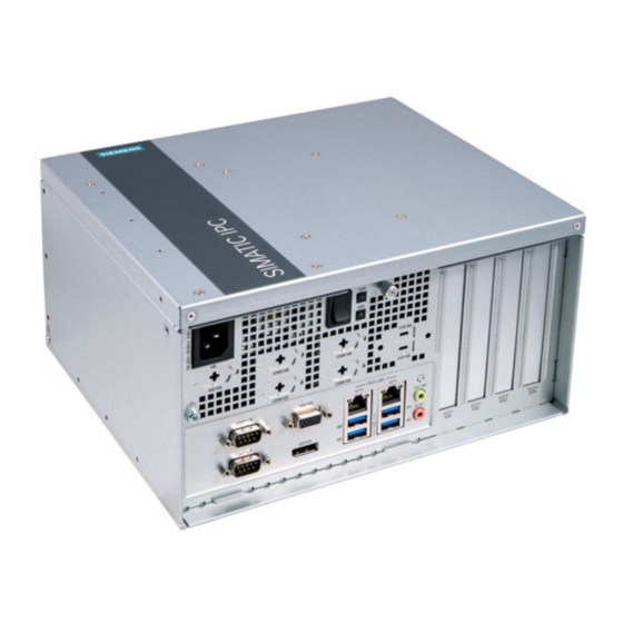
Overview 1.2 Structure of the devices Structure of the devices 1.2.1 Views of the basic device Front view The following picture shows the front view of IPC527G. ① Function earth ② Ports SIMATIC IPC527G Operating Instructions, 03/2019, A5E45491226-AA... -
Page 11: Interfaces Of The Basic Device
Overview 1.2 Structure of the devices Rear view ① Mounting bracket ② Air inlet 1.2.2 Interfaces of the basic device SIMATIC IPC527G Operating Instructions, 03/2019, A5E45491226-AA... -
Page 12: Status Displays
1.2.3 Status displays Display Meaning Description PC operating status display Hibernate, switched off or unplugged Green PC is in operation. Green flashing standby Display for hard disk access No accessing Green flashing Accessing data SIMATIC IPC527G Operating Instructions, 03/2019, A5E45491226-AA... -
Page 13: Safety Instructions
Siemens' products and solutions undergo continuous development to make them more secure. Siemens strongly recommends that product updates are applied as soon as they are available and that the latest product versions are used. Use of product versions that are no longer supported, and failure to apply the latest updates may increase customers' exposure to cyber threats. -
Page 14: General Safety Instructions
• Observe the safety and installation instructions for the expansion cards. • If in doubt, install the device in an enclosure that is compliant with sections 4.6 and 4.7.3 of the IEC/UL/EN/DIN-EN 60950-1 standard. SIMATIC IPC527G Operating Instructions, 03/2019, A5E45491226-AA... - Page 15 • Replace the lithium battery only with the type recommended by the manufacturer (type: CR2032). • For any requirements on product maintenance, contact Siemens Technical support (Page 104). • Do not throw lithium batteries into fire, do not solder on the cell body, do not recharge, do not open, do not short-circuit, do not reverse polarity, do not heat above 100°C and...
-
Page 16: Notes On Use
Validate the correct functioning of the plant to avoid functional restrictions. Note Use in an industrial environment without additional protective measures This device was designed for use in a normal industrial environment according to IEC 60721-3-3. SIMATIC IPC527G Operating Instructions, 03/2019, A5E45491226-AA... -
Page 17: Installing And Connecting The Device
A damaged packaging indicates that ambient conditions have already had an impact on the device. The device might be damaged. Do not dispose of the original packaging. Pack the device during transportation and storage. SIMATIC IPC527G Operating Instructions, 03/2019, A5E45491226-AA... -
Page 18: Identification Data Of The Device
The device can be clearly identified with the help of this identification data in case of repairs or theft. Enter the identification data in the following table: Identification date Source Value Serial number Product label S VP ... Order number of the device Product label 6AG4025-0... Production version Product label SIMATIC IPC527G Operating Instructions, 03/2019, A5E45491226-AA... - Page 19 Ethernet address 2 (MAC) Ethernet address 3 (MAC) (Optional) Product label The following image shows the product label on the SIMATIC IPC527G as an example. Note Replacement device without storage media When you order a replacement device, remove all the storage media from your device, for example HDD.
-
Page 20: Permitted Mounting Positions
Note The device is approved for indoor operation only. Ensure that the required minimum clearance of 100 mm to the area of the ventilation slots. The following mounting positions are permitted: Desk mounting position SIMATIC IPC527G Operating Instructions, 03/2019, A5E45491226-AA... -
Page 21: Mounting The Device
● Install the device only in one of the described permitted mounting positions. ● For installation of control cabinet, observe the country-specific regulations. ● All the external circuit of the device must be SELV circuit. SIMATIC IPC527G Operating Instructions, 03/2019, A5E45491226-AA... - Page 22 This can result in personal injuries or material damage. Ensure that the wall is capable of bearing four times the total weight of the device (including the brackets and expansion modules). The total weight of the device is approximately 5 kg. SIMATIC IPC527G Operating Instructions, 03/2019, A5E45491226-AA...
-
Page 23: Desk Mounting
● 6 × M3 screws from deliver package ● Another four screws for mounting to the wall Procedure for mounting Secure each mounting bracket with 3 × M3 screws to the device. The maximum penetration depth is 5 mm. SIMATIC IPC527G Operating Instructions, 03/2019, A5E45491226-AA... - Page 24 Installing and connecting the device 3.2 Mounting the device Use the marked threaded holes. The wall mounting has two mounting positions: ● The interfaces are at the left. ● The interfaces are at the right. SIMATIC IPC527G Operating Instructions, 03/2019, A5E45491226-AA...
-
Page 25: Book Mounting
In order to reserve some space for the ventilation, select the slot near the outside to secure the screw. ● The interfaces are also at the front. Rotate the device as shown in the above image horizontally by 180 degrees to mount the device. SIMATIC IPC527G Operating Instructions, 03/2019, A5E45491226-AA... -
Page 26: Tower Mounting
● Another four screws for mounting to a horizontal shelf Procedure for mounting Secure each mounting bracket with 3 × M3 screws to the device. The maximum penetration depth is 5 mm. Use the marked threaded holes. SIMATIC IPC527G Operating Instructions, 03/2019, A5E45491226-AA... -
Page 27: Connecting The Device
The function earth also improves the discharge of interference generated by external power cables, signal cables or cables for I/O modules to ground. The connection for the function earth is labeled with the following symbol: SIMATIC IPC527G Operating Instructions, 03/2019, A5E45491226-AA... - Page 28 Firmly attach the cable lug to the function earth connection on the device using the M4 thread (see part labeled). Connect the function earth to the protective conductor connection of the cabinet or the plant in which the device is installed. SIMATIC IPC527G Operating Instructions, 03/2019, A5E45491226-AA...
-
Page 29: Connecting The Power Supply
● Conductor cross-section ≤ 18 AWG ● Cable length ≤ 4.5 m 240 V supply voltage ● Type SJT with three conductors ● Conductor cross-section ≤ 18 AWG ● Cable length ≤ 4.5 m SIMATIC IPC527G Operating Instructions, 03/2019, A5E45491226-AA... - Page 30 ● conductor cross-section ≤ 18 AWG ● Cable length ≤ 4.5 m Connecting the power supply ① Connect the power cable to socket Insert the power cable in the electrical socket. ② Press the power button SIMATIC IPC527G Operating Instructions, 03/2019, A5E45491226-AA...
-
Page 31: Connect Device To Networks
Control level. Information on this can be found on the SIMATIC NET Manual Collection CD. The software package and the documentation are not included in the product package. Additional information You can find additional information on the Internet at: Technical support (https://support.industry.siemens.com/cs/?lc=en-WW) SIMATIC IPC527G Operating Instructions, 03/2019, A5E45491226-AA... -
Page 32: Commissioning The Device And Device Functions
Do not switch off the device during the entire installation process. Do not change the default values in the BIOS setup. Note If you install Windows 7 not by SIMATIC IPC527G USB stick, you need to do the following two steps: 1. Get the xHCI (USB) driver from the supplied USB stick. -
Page 33: Switching Off The Device
● Force to press the on/off switch for more than four seconds. The operating system is shut down. The "POWER" LED goes out. The device is switched off but not fully disconnected from the mains voltage. SIMATIC IPC527G Operating Instructions, 03/2019, A5E45491226-AA... - Page 34 Data on the drive may be lost. The device may be damaged. Perform a hardware reset only in the case of an emergency. For all operating systems: ● Press the on/off switch for more than four seconds. SIMATIC IPC527G Operating Instructions, 03/2019, A5E45491226-AA...
-
Page 35: Windows Security Center
● Real-time protection (Windows 7 only): Windows Defender displays warnings if spyware or possibly unwanted software is installed or executed on the computer. You will also receive a warning if programs attempt to modify important Windows settings. Configure the Security Center according to your requirements. SIMATIC IPC527G Operating Instructions, 03/2019, A5E45491226-AA... -
Page 36: Expanding And Assigning Parameters To The Device
Make sure that you take precautionary measures before you open the device. Requirement ● The device is disconnected from the power supply. ● All connecting cables on the device are unplugged. ● The device has been removed from the control cabinet. ● A PH2 screwdriver SIMATIC IPC527G Operating Instructions, 03/2019, A5E45491226-AA... - Page 37 Procedure - opening the device Loose the marked retaining screw. Lift up the cover. Procedure - closing the device To close the device, carry out the steps for opening the device in the reverse order. SIMATIC IPC527G Operating Instructions, 03/2019, A5E45491226-AA...
-
Page 38: Extension Card
Expansion cards that comply with the following standards are supported: ● PCI; Rev 2.3 Expansion cards with 5 V supply voltage can be operated ● PCIe; Gen. 1, Gen. 2, Gen. 3 Requirement ● The device is opened. ● A T10 screwdriver SIMATIC IPC527G Operating Instructions, 03/2019, A5E45491226-AA... - Page 39 Insert the expansion card into the slot. Secure the extension card with the screw you removed in step Procedure - Removing the extension card Follow the above steps in reverse order to remove the extension card. SIMATIC IPC527G Operating Instructions, 03/2019, A5E45491226-AA...
-
Page 40: Riser Card
Secure the riser card to the chassis with marked screws. Procedure - Removing the riser card Follow the above steps in reverse order to remove the riser card. SIMATIC IPC527G Operating Instructions, 03/2019, A5E45491226-AA... -
Page 41: Memory Module
ESD directives on handling electrostatic sensitive components. Note Siemens strongly recommends that you use only memory modules approved by Siemens. Siemens disclaims any liability for impairment of functions caused by the use of third-party memory modules. SIMATIC IPC527G... - Page 42 Insert and press the memory module into the socket until the retaining clips snap ba ck to the original place, and the memory module is seated properly. SIMATIC IPC527G Operating Instructions, 03/2019, A5E45491226-AA...
-
Page 43: Disk Drive
Hard Disk Drive (HDD) 500 GB to 2TB 2 × 2.5" HDD SATA Solid State Drive (SSD) 64 GB to 1TB 2 × 2.5" SSD SATA Requirement ● The device is open. ● A PH2 screwdriver SIMATIC IPC527G Operating Instructions, 03/2019, A5E45491226-AA... - Page 44 Lay down the device's rear panel including the drive. Remove the indicated screws. Take out the HDD or SSD. Procedure - Installing the disk drive Follow the steps in reverse order to install the disk drive. SIMATIC IPC527G Operating Instructions, 03/2019, A5E45491226-AA...
-
Page 45: Maintaining And Repairing The Device
Make sure you take precautionary measures even when you open the device, for example, when opening device doors, device covers or the housing cover. For more information, refer to the chapter "ESD Guideline (Page 58)" SIMATIC IPC527G Operating Instructions, 03/2019, A5E45491226-AA... -
Page 46: Installing And Removing Hardware
● T20 screwdriver for function earth connection ● PH2 screwdriver for all of the remaining screws Installing and removing hardware 6.3.1 Replacing the device fan Requirement ● The device is opened. ● A PH2 screwdriver SIMATIC IPC527G Operating Instructions, 03/2019, A5E45491226-AA... - Page 47 6.3 Installing and removing hardware Procedure - removing Remove the retaining screw. Unscrew the marked screws on the enclosure. Lift up the cover. ④ Pull out the fan plug ⑤ Take the fan out of the device. SIMATIC IPC527G Operating Instructions, 03/2019, A5E45491226-AA...
-
Page 48: Replacing The Backup Battery
– Rated voltage: 3 VDC – Max abnormal charging current: 10 mA • For any requirements on product maintenance, contact Siemens Technical support (Page 104). • Do not throw lithium batteries into fire, do not solder on the cell body, do not recharge, do not open, do not short-circuit, do not reverse polarity, do not heat above 100°C and... - Page 49 – Courant de charge anormal max. : 10 mA • Pour toute demande concernant la maintenance du produit, contactez le support technique (Page 104) Siemens. • Ne jetez pas au feu des piles au lithium, n'effectuez pas de soudage sur la pile, ne la rechargez pas, ne l'ouvrez pas, ne la court-circuitez pas, n'intervertissez pas les pôles,...
- Page 50 6.3 Installing and removing hardware Procedure Lay the cover on the desk. Move the marked clip to one side, and then take out the battery to replace with a new one. Reset the BIOS setup. SIMATIC IPC527G Operating Instructions, 03/2019, A5E45491226-AA...
-
Page 51: Installing The Software
Maintaining and repairing the device 6.4 Installing the software Installing the software Information on installation of the operating system is available on the Internet: Microsoft® Windows® 7 (https://support.industry.siemens.com/cs/ww/en/view/109764660) 6.4.1 Installing the drivers Requirements ● Windows 7 is installed in your IPC. - Page 52 4. Click Yes to confirm the user account control question. 5. Click Next to continue. 6. Select the radio button before "I accept the terms in the License Agreement", and click Next to accept license agreement. SIMATIC IPC527G Operating Instructions, 03/2019, A5E45491226-AA...
- Page 53 6. Select the radio button before "I accept the terms in the license agreement", and click Next to accept license agreement. 7. Set the setup option as you like and click Next. 8. Click Install to start the driver installation. 9. Click Finish. The installation is completed. SIMATIC IPC527G Operating Instructions, 03/2019, A5E45491226-AA...
-
Page 54: Recycling And Disposal
Recycling and disposal The devices described in these operating instructions can be recycled thanks to their low level of pollutants. Contact a certified disposal service company for environmentally sound recycling and disposal of your old devices. SIMATIC IPC527G Operating Instructions, 03/2019, A5E45491226-AA... -
Page 55: Technical Specifications
ISO 9001 certificate The Siemens quality management system for all production processes (development, production and sales) meets the requirements of GB/T 19001-2008/ISO 9001:2015, ISO 14001:2015 + Cor. 1:2009 and BS OHSAS 18001:2007. - Page 56 CANADA Canadian notice This Class A digital apparatus complies with Canadian ICES-003. Avis Canadian Cet appareil numérique de la classe A est conforme à la norme NMB-003 du Canada. SIMATIC IPC527G Operating Instructions, 03/2019, A5E45491226-AA...
- Page 57 Technical specifications 7.1 Certificates and approvals Responsible party for Supplier's Declaration of Conformity Siemens Industry, Inc. Digital Factory ¨C Factory Automation 5300 Triangle Parkway, Suite 100 Norcross, GA 30092 Mail to: (amps.automation@siemens.com) UL approval The following approvals are available for the device: ●...
-
Page 58: Directives And Declarations
The consequences are incalculable and range from unforeseeable malfunctions to a total failure of the machine or system. Avoid touching components directly. Make sure that persons, the workstation and the packaging are properly grounded. SIMATIC IPC527G Operating Instructions, 03/2019, A5E45491226-AA... - Page 59 There is no equipotential bonding without grounding. An electrostatic charge is not discharged and may damage the ESD. Protect yourself against discharge of static electricity. When working with electrostatic sensitive devices, make sure that the person and the workplace are properly grounded. SIMATIC IPC527G Operating Instructions, 03/2019, A5E45491226-AA...
-
Page 60: Dimension Drawings
– Discharge your body electrostatically before you take a measurement at a module. Do so by touching grounded metallic parts. Always use grounded measuring instruments. Dimension drawings Desk mounting and Wall mounting (for the interfaces are at the left and right) all dimensions in mm SIMATIC IPC527G Operating Instructions, 03/2019, A5E45491226-AA... - Page 61 Technical specifications 7.3 Dimension drawings Book mounting (for the interfaces are at the front) all dimensions in mm Tower mounting all dimensions in mm SIMATIC IPC527G Operating Instructions, 03/2019, A5E45491226-AA...
-
Page 62: Technical Data
± 2 kV / 5 kHz /100 in accordance with IEC 61000-4-4; Length of signal port extension cable ≥ 30 m Surge: ± 1 kV line-to-line; ± 2 kV line-to-earth in accordance with IEC 61000-4-5; Length of signal port extension cable ≥ 30 m SIMATIC IPC527G Operating Instructions, 03/2019, A5E45491226-AA... - Page 63 Max. permitted totally power ≤ 25 W loss for PCI slot Max. permitted power loss ≤ 45 W over all slots In total, the 3.3 Vaux current of 1.2 A must not be exceeded. SIMATIC IPC527G Operating Instructions, 03/2019, A5E45491226-AA...
- Page 64 Output) Digital Input (5V TTL) and Output (5V 12mA) Keyboard, mouse Connection via USB port In BIOS Setup, you can configure support for RS 232/ RS 422/ RS 485 for COM1 and COM2 ports. SIMATIC IPC527G Operating Instructions, 03/2019, A5E45491226-AA...
-
Page 65: Environmental Conditions
8.4 to 500 Hz: 9.8 m/s • Shock resistance, tested in accordance with IEC 60068-2-27 Operation With HDD: 9.81 m/s , 20 ms • With SSD: 150 m/s², 11 ms • Storage/transport 250 m/s , 6 ms • SIMATIC IPC527G Operating Instructions, 03/2019, A5E45491226-AA... -
Page 66: Power Demand Of The Components
• Total output power of +5 V and +3.3 V should be less than 91Watts. • DC output power should be less than 350Watts. • When AC input below 115 V, DC output power should derate 20% load at 50 ℃. SIMATIC IPC527G Operating Instructions, 03/2019, A5E45491226-AA... -
Page 67: Hardware Descriptions
1 × VGA • DIO (Digital Input Output) External DB9 connector Digital Input (5V TTL) and Output (5V 12mA) Only four of these USB ports may be operated simultaneously in high current mode, max. 10 W. SIMATIC IPC527G Operating Instructions, 03/2019, A5E45491226-AA... -
Page 68: Serial Interface
Receive data - (I) for full-duplex mode Signal ground Pin assignment RS485 Short description Meaning Data- Transmit / receive data - (I/O) for half-duplex mode Data+ Transmit / receive data+ (I/O) for half-duplex mode Signal ground SIMATIC IPC527G Operating Instructions, 03/2019, A5E45491226-AA... -
Page 69: Usb 2.0 Port
DisplayPort Short name Meaning Input / output ML_Lane0+ DP data 0+ Output Ground ML_Lane0- DP data 0- Output ML_Lane1+ DP data 1+ Output Ground ML_Lane1- DP data 1- Output ML_Lane2+ DP data 2+ Output SIMATIC IPC527G Operating Instructions, 03/2019, A5E45491226-AA... -
Page 70: Ethernet Port
LED 1 Off: Port is Not Active Lit orange: Port is Active, but No Data Activity Blinking: Port is Active and there is Data Activity LED 2 Off: 10Mbps Lit red: 100Mbps Lit green: 1Gbps SIMATIC IPC527G Operating Instructions, 03/2019, A5E45491226-AA... -
Page 71: Dio Port
Dynamic Digital IO page of Advanced menu (Page 80) in BIOS. The DIO setting tool helps you to configure the DIO pin and modify the registers. If you need DIO setting tool, contact Siemens Technical support (Page 104). SIMATIC IPC527G... -
Page 72: Internal Interfaces
– 255: the modification fails. – Others: the modification succeeds. 7.5.3 Internal interfaces 7.5.3.1 Overview of internal interfaces Interface Position Connector Description Internal SATA 3.0 SATA M.2 2242 Key B (SATA) SIMATIC IPC527G Operating Instructions, 03/2019, A5E45491226-AA... -
Page 73: M.2 Interface
PERN0/SATA_B+ GNSS2(0/1.8V) PERP0/SATA_B- GNSS3(0/1.8V) GND7 GNSS4(0/1.8V) PETN0/SATA_A- PERST#(O)(0/3.3V) PETP0/SATA_A+ CLKREQ#(IO)(0/3.3V) GND8 PEWAKE#(IO)(0/3.3V) REFCLKN REFCLKP GND9 COEX3(I/O)(0/1.8V) ANTCTL0(I)(0/1.8V) COEX_RXD(I)(0/1.8V) ANTCTL1(I)(0/1.8V) COEX_TXD(O)(0/1.8V) ANTCTL2(I)(0/1.8V) SIM_DETECT(O) ANTCTL3(I)(0/1.8V) SUSCLK(32KHZ)(O)(0/3.3V) RESET#(O)(0/1.8V) 3.3VAUX3 PEDET(OC_PCIE/GND_SATA) 3.3VAUX4 GND10 3.3VAUX5 GND11 NP_NC2 USB3.0IND(OC_USB3.0/GND_OTHER SIDF2 SIMATIC IPC527G Operating Instructions, 03/2019, A5E45491226-AA... -
Page 74: Currently Allocated System Resources
1. Power on the device. 2. Press DELETE or ESC key on your keyboard during the Power - On - Self - Test (POST) when the SIEMENS logo is shown on screen. The Aptio TSE main BIOS setup menu is displayed. - Page 75 ● Save & Exit: For selecting the exit options and loading default settings. Function description fields Function description fields are at the top right corner of the menu screen and a brief description of the selected item. SIMATIC IPC527G Operating Instructions, 03/2019, A5E45491226-AA...
- Page 76 A configurable field is enclosed in brackets, and is highlighted when selected. To change the value of a field, select it and press Enter to display a list of options. Menu items Menu items are system parameters in each page and vary according to different menu pages. SIMATIC IPC527G Operating Instructions, 03/2019, A5E45491226-AA...
-
Page 77: Main Menu
Show the BIOS release version information. Release Date Show the BIOS release date information. BIOS Vendor Show the BIOS vendor information. ME Version Show the ME version information. System Language You can only choose the BIOS language version: [English]. SIMATIC IPC527G Operating Instructions, 03/2019, A5E45491226-AA... - Page 78 The Administrator and User passwords activate two different levels of password security. After the passwords are set, you must enter a password every time when you enter BIOS. Administrator Password If you have set an administrator password, Siemens recommends that you enter the administrator password for accessing the system. SIMATIC IPC527G...
- Page 79 After you clear the password, the User Password item on top of the screen shows Not Installed. Note Record the new password when the password is changed. If you forget the password, you can contact Siemens Technical support (Page 104). SIMATIC IPC527G Operating Instructions, 03/2019, A5E45491226-AA...
-
Page 80: Advanced Menu
[Enabled]: A VMM can utilize the additional hardware capabilities • [Disabled] • nology provided by Vanderpool Technology. [Disabled]: Disable this function. • Turbo Mode Enable or disable the processor Turbo Mode. [Enabled] [Enabled] • [Disabled] • SIMATIC IPC527G Operating Instructions, 03/2019, A5E45491226-AA... - Page 81 ✓ ✓ [Auto] × × ✓ × × ✓ × × ✓ [Disabled] [CPU Graphics] ✓ ✓ × ✓ ✓ × ✓ ✓ ✓ [PEG] × × ✓ × × ✓ × × ✓ SIMATIC IPC527G Operating Instructions, 03/2019, A5E45491226-AA...
- Page 82 [Auto]: The system detects the presence of USB devices at • startup. If detected, the USB controller legacy mode is enabled. If no USB device is detected, the legacy USB support is disa- bled. SIMATIC IPC527G Operating Instructions, 03/2019, A5E45491226-AA...
- Page 83 [IO=2F8h; IRQ=3, 4, 5, • 6, 7, 8, 9, 10, 11, 12;] [IO=3E8h; IRQ=3, 4, 5, • 6, 7, 8, 9, 10, 11, 12;] [IO=2E8h; IRQ=3, 4, 5, • 6, 7, 8, 9, 10, 11, 12;] SIMATIC IPC527G Operating Instructions, 03/2019, A5E45491226-AA...
- Page 84 [IO=2E8h; IRQ=3, 4, 5, • 6, 7, 8, 9, 10, 11, 12;] [IO=2F0h; IRQ=3, 4, 5, • 6, 7, 8, 9, 10, 11, 12;] [IO=2E0h; IRQ=3, 4, 5, • 6, 7, 8, 9, 10, 11, 12;] SIMATIC IPC527G Operating Instructions, 03/2019, A5E45491226-AA...
- Page 85 [Disabled] • Ipv4 PXE Enable or disable the Ipv4 PXE Boot support. [Disabled] [Enabled] • Support [Disabled] • Ipv6 PXE Enable or disable the Ipv6 PXE Boot support. [Disabled] [Enabled] • Support [Disabled] • SIMATIC IPC527G Operating Instructions, 03/2019, A5E45491226-AA...
- Page 86 Enable or disable the PCIEX4. [Enabled] [Enabled] • [Disabled] • PCIEX4 Configure PCIEX4 Gen1-Gen3. [Auto] [Auto] • Speed [Gen1] • [Gen2] • PCIEX4 Detect Non-Compliance PCI Express Device in PCIEX4. [Disabled] [Enabled] • Non- [Disabled] • Compliance mode SIMATIC IPC527G Operating Instructions, 03/2019, A5E45491226-AA...
-
Page 87: Hardware Monitor Menu
[Silent Mode] • according to the motherboard temperature. [Disabled • [Silent Mode]: The chassis fan runs at low speed with less • Mode] noise. [Disabled Mode]: The chassis fan runs at full speed. • SIMATIC IPC527G Operating Instructions, 03/2019, A5E45491226-AA... -
Page 88: Boot Menu
Boot menu Boot menu The Boot menu allows you to change the system boot options. Boot Configuration In the Boot Configuration page, you can modify the boot up screen between POST message and SIEMENS logo. System Function description Configuration Default setting... - Page 89 • age devices during POST(power-on self-test). Boot from PCI-E Expansion devices will run the selected type first during [Legacy only] [Legacy only] • PCI-E Ex- the system boot. [UEFI driver first] • pansion Devices SIMATIC IPC527G Operating Instructions, 03/2019, A5E45491226-AA...
-
Page 90: Save & Exit Menu
Note • Select the boot device during system startup, press <F10> when SIEMENS Logo appears. • Access Windows OS in Safe Mode, press <F8> after POST. - Page 91 2. Select Yes and press Enter key to load optimized defaults. Or Select No to quit. EZ Flash 3 Utility This option is used for updating BIOS. Press Enter to launch the EZ Flash 3 screen. SIMATIC IPC527G Operating Instructions, 03/2019, A5E45491226-AA...
-
Page 92: Appendix Motherboard
Use a grounding wrist strap at all times. Place all electronic components on a static‐dissipative surface or in a static‐shielded bag when th ey are not in the chassis. SIMATIC IPC527G Operating Instructions, 03/2019, A5E45491226-AA... - Page 93 A pair of needle nose pliers may be helpful when working with jumpers. If you have any questions about the best hardware configuration for you application, contact your local distributor or sales representative before you make any change. SIMATIC IPC527G Operating Instructions, 03/2019, A5E45491226-AA...
- Page 94 Appendix Motherboard A.1 Jumpers Clear CMOS Note Set the jumper back to protected mode after clearing CMOS. SIMATIC IPC527G Operating Instructions, 03/2019, A5E45491226-AA...
- Page 95 Appendix Motherboard A.1 Jumpers COM1/COM2 Ring/+5V/+12V selection (6-pin COM1_SEL, COM2_SEL) Intel® ME jumper (3-pin DIS_ME) SIMATIC IPC527G Operating Instructions, 03/2019, A5E45491226-AA...
-
Page 96: Internal Connector
A.2 Internal Connector Internal Connector A.2.1 Intel® H110 Serial ATA 6.0Gb/s connectors (SATA6G_1~2) Intel® H110 Serial ATA 6.0 Gb/s connectors connect to Serial ATA 6.0 Gb/s hard disk drives through Serial ATA 6.0 Gb/s signal cables. SIMATIC IPC527G Operating Instructions, 03/2019, A5E45491226-AA... -
Page 97: Cpu And Chassis Fan Connectors (Cpu_Fan, Cha_Fan)
In order to prevent the damage from insufficient air flow inside the system to motherboard components, connect the fan cables to the fan connectors. Do not place jumper caps on the fan connectors. The CPU_FAN connector supports a CPU fan of maximum 1A (12 W) fan power. SIMATIC IPC527G Operating Instructions, 03/2019, A5E45491226-AA... -
Page 98: Atx Power Connectors (Eatxpwr, Atx12V, Atx_Pwr)
• The 4‐Pin ATX +12 V power plug must be connected, otherwise the system cannot be booted up. • Siemens recommends that you use a PSU with higher power output when configuring a system with more power-consuming devices or when you intend to install additional devices. -
Page 99: Digital I/O Connector (Dio)
I/O pin can be individually programmed to support various devices. Note To configure the I/O pins in BIOS, navigate to Dynamic Digital IO selection in Advanced tab. For the detailed information, refer to Advanced menu (Page 80). SIMATIC IPC527G Operating Instructions, 03/2019, A5E45491226-AA... -
Page 100: Serial Port Connectors (Com3, Com4)
Serial port connectors (COM3, COM4) These connectors are for serial (COM) ports. Connect the serial port module cable to these connectors, then install the module to a slot opening at the back of the system chassis. SIMATIC IPC527G Operating Instructions, 03/2019, A5E45491226-AA... -
Page 101: M.2 B Key Slot
A.2 Internal Connector A.2.6 M.2 B Key slot This socket allows you to install an M.2 module. For the detailed information, refer to M.2 interface (Page 73). Note This slot supports type 2242 SATA storage devices. SIMATIC IPC527G Operating Instructions, 03/2019, A5E45491226-AA... -
Page 102: Usb 2.0 Connectors (Usb56, Usb78, Usb9)
Connect a USB module cable to any of these connectors, then install the module to a slot opening at the back of the system chassis. This USB connectors comply with USB 2.0 specifications and support up to 480Mbps connection speed. SIMATIC IPC527G Operating Instructions, 03/2019, A5E45491226-AA... -
Page 103: System Panel Connector (F_Panel)
ATX power button/soft-off button (2-pin PWR_BTN) This connector is for the system power button. Reset button (2-pin RESET) This 2-pin connector is for the chassis-mounted reset button for system reboot without turning off the system power. SIMATIC IPC527G Operating Instructions, 03/2019, A5E45491226-AA... -
Page 104: Technical Support
Tools & downloads Please check regularly if updates and hotfixes are available for download to your device. The download area is available on the Internet at the following link: After Sales Information System SIMATIC IPC/PG (http://www.siemens.com/asis) SIMATIC IPC527G Operating Instructions, 03/2019, A5E45491226-AA... -
Page 105: Troubleshooting
Wrong time and/or date on the 1. Open the BIOS Setup. 2. Set the time or date. Although the BIOS setting is The backup battery is dead. Replace the backup battery. OK, the time and data are still wrong SIMATIC IPC527G Operating Instructions, 03/2019, A5E45491226-AA... -
Page 106: Notes On The Use Of Third-Party Modules
Different pin assignment • being used was the cause of the fault. Replace the thrid- party module with a Siemens module or contact the module supplier. If the device still crashes, contact your technical support team. Insufficient output of an external Use a higher capacity power supply •... -
Page 107: Markings And Symbols
Opening for Kensington lock opening Attention ESD (Electrostatic sensitive Warning of hot surface device) Operator controls Symbol Meaning Symbol Meaning On/off switch, without electrical isola- Eject CD/DVD tion On/off switch, without electrical isola- tion SIMATIC IPC527G Operating Instructions, 03/2019, A5E45491226-AA... -
Page 108: Certificates, Approvals And Markings
CE markings for European countries Marking of Federal Communications Commission for the USA EFUP (Environment Friendly Use Approved for Korea Period) marking for China Test mark of the Underwriters La- Disposal information, observe the boratories local regulations. SIMATIC IPC527G Operating Instructions, 03/2019, A5E45491226-AA... -
Page 109: Interfaces
DVI-D interface Line In LAN interface, not approved for con- Line Out necting WAN or telephone Serial port Microphone input USB port Universal Audio Jack USB 2.0 high-speed port Headphone output USB 3.0 super-speed port SIMATIC IPC527G Operating Instructions, 03/2019, A5E45491226-AA... -
Page 110: List Of Abbreviations
Data Carrier Detect Data carrier signal detection Direct Memory Access Disk Operating System DisplayPort Deutsche Gesellschaft zur Zer- tifizierung von Qualitätsmanage- ment mBH Data Set Ready Ready for operation Data Terminal Ready Data terminal is ready SIMATIC IPC527G Operating Instructions, 03/2019, A5E45491226-AA... - Page 111 Language localization in Windows NEMA National Electrical Manufacturers Association NTFS New Technology File System NVRAM Non Volatile Random Access Non-volatile data memory. Data memory is re- Memory tained without external power supply. Optical Disk Drive SIMATIC IPC527G Operating Instructions, 03/2019, A5E45491226-AA...
- Page 112 Universal Serial Bus Verband der Elektrotechnik, El- ektronik und Informationstechnik e.V (Association for Electrical, Electronic and Information Tech- nologies) Virtualization Technology Intel technology which provides a virtual, closed environment. SIMATIC IPC527G Operating Instructions, 03/2019, A5E45491226-AA...
- Page 113 List of abbreviations VT-d Virtualization Technology for Enables the direct assignment of a device (e.g. Directed I/O network adapter) to a virtual device. Watchdog Program monitoring with error detection and alarming. SIMATIC IPC527G Operating Instructions, 03/2019, A5E45491226-AA...
-
Page 114: Glossary
EC directives such as the EMC Directive. CFast The faster SATA protocol is used with the CFast standard for memory cards based on CompactFlash. The connectors on these cards are not compatible with a classic CompactFlash card. SIMATIC IPC527G Operating Instructions, 03/2019, A5E45491226-AA... - Page 115 The data are stored in a configuration file and enable the operating system to load the correct device drivers and configure the correct device parameters. . If changes are made to the hardware configuration, the user can change entries in the configuration file using the SETUP program. . SIMATIC IPC527G Operating Instructions, 03/2019, A5E45491226-AA...
- Page 116 10/100/1000 Mbps. Execute Disable Capability Hardware implementation that prevents mutual memory accesses by programs and applications. It is only effective when all relevant system components, such as processors, operating systems and applications are supported. SIMATIC IPC527G Operating Instructions, 03/2019, A5E45491226-AA...
- Page 117 Intel Active Management Technology This technology permits diagnostics, management and remote control of PCs. It is only effective when all relevant system components, such as processors, operating systems and applications are supported. SIMATIC IPC527G Operating Instructions, 03/2019, A5E45491226-AA...
- Page 118 Conventional drives can be used as USB devices. License key The license key represents the electronic license stamp of a license. Siemens AG issues a license key for each software that is protected by a license. License key USB flash drive The license key USB flash drive contains the authorizations or license keys required to enable protected SIMATIC software.
- Page 119 Restricted Access Location: Installation of the device in a production facility with restricted access, for example, a locked control cabinet. Reset Hardware reset: Reset/restart of the PC using a button/switch. Restart Warm restart of a computer without switching the power off (Ctrl + Alt + Del) SIMATIC IPC527G Operating Instructions, 03/2019, A5E45491226-AA...
- Page 120 Wake on LAN Wake on Local area network. This function allows the PC to be started via the LAN interface. SIMATIC IPC527G Operating Instructions, 03/2019, A5E45491226-AA...
- Page 121 Glossary Warm restart The restart of a computer after a program was aborted. The operating system is loaded and restarted again. The CTRL+ ALT+ DEL hotkey can be used to initiate a warm restart. SIMATIC IPC527G Operating Instructions, 03/2019, A5E45491226-AA...
-
Page 122: Index
Industrial Ethernet, 31 Directive PROFINET, 31 ESD Directive, 58 Interface, 64 Disk drive Interfaces Installing, 44 DisplayPort, 69 Removing, 44 USB 2.0, 69 DisplayPort USB 3.0, 69 Interface, 69 IT communication, 31 Drive, 64 SIMATIC IPC527G Operating Instructions, 03/2019, A5E45491226-AA... - Page 123 Protection class, 62 Windows Security Center, 35 Protective measure Static electricity, 60 Radiation, 15 High frequency radiation, 15 RAM, 63 Real-time protection, 35 Rear view, 11 Repairs, 45, 46 Riser card Installing, 40 Removing, 40 SIMATIC IPC527G Operating Instructions, 03/2019, A5E45491226-AA...
Need help?
Do you have a question about the Simatic IPC527G and is the answer not in the manual?
Questions and answers