Table of Contents
Advertisement
Quick Links
Advertisement
Table of Contents

Related Manuals for Bender ISOMETER isoPV1685RTU


Summary of Contents for Bender ISOMETER isoPV1685RTU
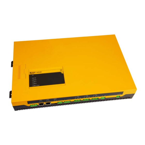
- Page 1 Manual ISOMETER® isoPV1685RTU isoPV1685P Insulation monitoring device for unearthed DC systems for photovoltaic systems up to 1500 V isoPV1685RTU: software version D0532 V2.0x isoPV1685P : software version D0525 V2.0x isoPV1685xxx_D00007_05_M_XXEN/02.2020...
- Page 2 E-Mail: info@bender.de Web: www.bender.de Customer service Service-Hotline: 0700-BenderHelp (Telephone and Fax) Carl-Benz-Straße 8 • 35305 Gruenberg • Germany © Bender GmbH & Co. KG Tel.:+49 6401 807-760 All rights reserved. Fax:+49 6401 807-629 Reproduction only with permission of the publisher.
-
Page 3: Table Of Contents
Table of contents 1. Important information ..............5 3.4.2 Automatic self test ..........11 3.4.3 Manual self test . - Page 4 Table of contents Table of contents 8. Device communication ..............22 8.1 RS-485 interface with BMS and Modbus RTU protocol ....22 8.1.1 Topology RS-485 network ........22 8.2 BMS bus.
-
Page 5: Important Information
1.2 Technical support 1.2.1 End customer support and advice This manual is intended for qualified personnel working in electrical Technical support by phone or e-mail for all Bender products engineering and electronics! • Questions concerning specific customer applications • Commissioning •... -
Page 6: Training Courses
• Old electrical and electronic equipment from users other than private households Sale and delivery conditions can be obtained from Bender in printed or electronic format. which was introduced to the market after 13 August 2005 must be taken back by the manufacturer and disposed of properly. -
Page 7: Safety Instructions
Make sure that the basic settings meet the requirements of the IT system. Part of the device documentation in addition to this manual is the enclosed "Safety in- Persons without the required expertise, in particular children, must not structions for Bender products". have access to or contact with the ISOMETER®. WARNING 2.2 Working on electrical installations... -
Page 8: Address Setting And Termination
Safety instructions Safety instructions 2.5 Intended use Unspecified frequency range! When connecting to an IT system with frequency components below the specified frequency range, the response times and response values may Only qualified personnel are permitted to carry out the work necessary differ from the indicated technical data. -
Page 9: Function
3. Function Function 3.1 Features isoPV1685RTU and isoPV1685P 3.2 Product description The ISOMETER® isoPV1685RTU is an insulation monitoring device for IT systems in accord- ance with IEC 61557-8. The ISOMETER® isoPV1685P is an insulation monitoring device for The device version isoPV1685P provides a locating current injector. IT systems in accordance with IEC 61557-8 and IEC 61557-9. -
Page 10: Μsd Card
Function Function 3.3.2 μSD card 3.3.4 Insulation fault location (isoPV1685P) The integrated μSD card is used as data logger for storing all relevant events. For insulation fault location, a suitable locating current is superimposed onto the faulty PV system with which EDS... insulation fault locators can locate insulation faults. The The following measured values, statuses and alarms are stored during operation: ≤... -
Page 11: History Memory
Function Function 3.3.7 History memory Only in the manual self test mode (via the CAN or RS-485 interface), the following tests can be carried out: All warnings, alarms and device errors including "Come", "Go" and "Acknowledgement" • Internal Flash timestamps are stored in the internal history memory. •... -
Page 12: Device Overview
4. Device overview 4.1 Dimensions 5,2 mm isoPV1685 ® ISOMETER PGH ON SERVICE ALARM 1 ALARM 2 ALARM 3 (I ∆ 106 mm 39,8 mm 40,75 mm 55,7 mm 51 mm 368 mm 383 mm 401,5 mm isoPV1685xxx_D00007_05_M_XXEN/02.2020... -
Page 13: Connections
Device overview 4.2 Connections A, B, S 31, 32, 34 11, 12, 14 A1, A2 RS-485 bus Relay output Relay output for Supply voltage DC 24 connection (A,B) for device er- alarm CAN 1 Protocol: BMS ror ("Service" insulation fault Arbitrary polarity CAN 2 or Modbus... - Page 14 Device overview DIP switch (SS8103) LEDs: - ON: operation (flashes) Button (ST6101) - PGH ON: Insulation fault location (isoPV1685P) - SERVICE: device error, connection fault Memory card (SD card) - ALARM 1: Insulation fault - ALARM 2: Insulation fault isoPV1685 ®...
-
Page 15: Display And Operating Controls
Device overview Device overview 4.3 Display and operating controls 4.3.2 Operating elements in the service lid The representation below shows the position of the operating elements 4.3.1 Display elements Operating Function elements SS8103 isoPV1685RTU: PGH ON • Switching between BMS and Modbus: A4 ST6101 •... -
Page 16: Installation And Connection
5. Installation and connection Installation and connection 5.1 Installation Risk of property damage due to unprofessional installation! If more than one insulation monitoring device is connected to a conduc- Install the device using four M5 screws, also refer to the dimension diagram on Page 12 tively connected system, the system can be damaged. -
Page 17: Wiring Diagram
Installation and connection Installation and connection 5.2.2 Wiring diagram Connect the device with the help of the connection and terminal diagram. Use the adja- Terminal, cent legend. Connections Socket I2+, I2– Currently has no function, digital input. Digital input I1+, I1– L1/+ L2/- isoPV1685P: Starting the insulation fault location in the manual mode... -
Page 18: Commissioning
6. Commissioning Commissioning 6.1 Commissioning flow chart insulation fault monitoring 6.2 Commissioning flow chart insulation fault location (isoPV1685P only) Netz = IT-System ? nein isoPV1685… nicht geeignet Komponenten des Vor dem Geräteanschluss die Isolationsfehlersuchsystems Anlage spannungsfrei schalten ! EDS440 und zugehörige Messwandler installieren ≤... -
Page 19: Settings
7. Settings Settings 7.1 Setting BMS address Setting the system leakage capacitance or measurement speed Refer to "Setting the BMS address" on page 7.2 Setting an alarm for insulation faults These settings may only be changed when the PV voltage is switched off. You can set the limit values for alarm 1 and alarm 2 of the ISOMETER®... -
Page 20: Parameter Setting Of The Insulation Fault Location
Settings Settings 7.4 Parameter setting of the insulation fault location 7.5 Deactivating the device (isoPV1685P only) When the device is deactivated, the coupling unit of the device (isoPV1685P only) is gal- vanically isolated from the system being monitored. Set the value of the locating current required for insulation fault location to 1...50 mA. You can make this setting via the BMS bus by means of a BMS gateway (e.g. -
Page 21: Parameter Setting With The Iso1685 Set Tool
By using the iso1685 set program you confirm the following conditions: Bender provides this software free of charge and without any warranty. By using this software you agree that you are using the software at your own risk. Bender does not assume any responsibility for possible software er- rors or defects and does not guarantee that the software works error-free and reliably. -
Page 22: Device Communication
8. Device communication Device communication 8.1 RS-485 interface with BMS and Modbus RTU protocol The isoPV1685P uses the RS-485 interface for the BMS bus. The isoPV1685RTU uses the RS-485 interface for the BMS bus or for Modbus CAN 2 CAN 2 RS-485 Term. -
Page 23: Bms Bus
8.2.1 BMS protocol can be carried out via the backup master. This protocol is an essential part of the Bender measuring device interface (BMS bus pro- 8.2.2 Commissioning of an RS-485 network with BMS protocol tocol). Data transmission generally makes use of ASCII characters. -
Page 24: Alarm And Operating Messages Via Bms Bus
Device communication Device communication 8.2.4 Alarm and operating messages via BMS bus DIP switch SS8103 Messages are transmitted via up to 12 BMS channels. All alarm and operating messages Switch position: BMS addr. that may occur are described below. Up = Off Down = On 8.2.4.1 Alarm messages... -
Page 25: Performing A Firmware Update Via The Bms Bus
The firmware can be updated via the BMS bus using the BMS Update Manager which can The following list contains all relevant error codes output via BMS bus or CAN bus . The be obtained from Bender. right-hand column describes the relevant action to be taken in each case. 8.3 CAN bus Fehlercode Fehler Maßnahme... -
Page 26: Modbus Rtu (Isopv1685Rtu)
Set the Modbus address by means of switches 2 to 5 of the DIP switch SS8103. The Modbus RTU is used for integration of Bender devices featuring a Modbus RTU inter- face into systems with a Condition Monitor (e.g. CP700, COM465xP) or for integration into... -
Page 27: Modbus Register Assignment
Device communication 8.5.6 Modbus register assignment Read: Function Code 0x03 = 03 (Read Holding Registers); Write: Function Code 0x10 = 16 (Write Multiple Registers) Registeradr. in Registeradr. in Anzahl Hexadezimal Dezimal Beschreibung Words Datentyp Modus Bereich Einheit Kommentar/Wert Standard Geräteinformation 0x510 1296 Gerätename... - Page 28 Device communication Registeradr. in Registeradr. in Anzahl Hexadezimal Dezimal Beschreibung Words Datentyp Modus Bereich Einheit Kommentar/Wert Standard Parameter 200 … 0x3000 12288 Ansprechwert Vorwarnung UInt32 1.000.000 Ω 10.000 200 … 0x3002 12290 Ansprechwert Alarm UInt32 1.000.000 Ω 1.000 0x3004 12292 Fehlerspeicher UInt16 0 …...
-
Page 29: Diagrams
9. Diagrams Diagrams 9.1 The leakage capacitance depends on the insulation 9.2 Response time for insulation measurement resistance isoPV1685xxx_D00007_05_M_XXEN/02.2020... -
Page 30: Example Of Alarms Stored In The History Memory
Diagrams Diagrams 9.3 Example of alarms stored in the history memory Index Alarm Unit Test Start Time Ack Time Stop Time Idx 231 ID 43 insulation fault <200 =200 None 27.04.12 13:59 – 27.04.12 13:59 Explanation Time of Index history Minimum Maximum Alarm during... -
Page 31: Factory Settings
10. Factory settings Factory settings Value isoPV1685P: isoPV1685RTU: Parameters Status can be set via can be set via Insulation response value R 10 kΩ BMS, CAN BMS, Modbus, CAN Insulation response value R 1 kΩ BMS, CAN BMS, Modbus, CAN Fault memory insulation measure- BMS, Modbus ment... -
Page 32: Technical Data
Supply voltage U (see also device nameplate) ........................DC 18...30 V CAN: Power consumption ..................................≤ 7 W Protocol ............................acc. to SMA/Bender specification V2.5 Measuring circuit for insulation monitoring Frame format ..............................CAN 2.0A 11-bit identifier Measuring voltage U (peak value)............................... -
Page 33: Standards, Approvals And Certifications
Technical data Technical data Connection (except system coupling) 11.2 Standards, approvals and certifications Connection type............................pluggable push-wire terminals The isoPV1685 was designed according to the following standards: Connection, rigid/flexible..........................0.2...2.5 mm /0.2...2.5 mm • DIN EN 61557-8 (VDE 0413-8) Connection, flexible with ferrule, without/with plastic sleeve..................0.25...2.5 mm Conductor sizes (AWG) .................................24…12 •... -
Page 34: Index
INDEX Address setting 8 History memory 11 Alarm messages 24 Alarm relays K1, K2, K3 10 Installation of the device 16 Insulation fault location 10 BMS bus Insulation monitoring 10 Alarm messages 24 iso1685FR set 21 Commissioning 23 Master 23 Leakage capacitance 29 Number of bus nodes 23 LEDs... - Page 35 Index Index Wiring diagram 17 Parameter setting of the insulation fault location 20 Work activities on electrical installations 7 Product description 9 μSD card 15 Resetting error messages 25 Response time Insulation measurement 29 RS-485 interface 22 RS-485 network Correct arrangement 22 Wrong arrangement 22 Safety instructions 7 Self test...
- Page 36 Londorfer Straße 65 • 35305 Gruenberg • Germany Carl-Benz-Straße 8 • 35305 Gruenberg • Germany Tel.: +49 6401 807-0 Tel.: +49 6401 807-760 Fax: +49 6401 807-259 Fax: +49 6401 807-629 Email: info@bender.de Email: info@bender-service.com Web: www.bender.de Web: http://www.bender.de Group Photos: Bender archive and bendersystembau archive.
Need help?
Do you have a question about the ISOMETER isoPV1685RTU and is the answer not in the manual?
Questions and answers