Table of Contents
Advertisement
Quick Links
Technical Publication
Installation Guidelines - HELIAX
Solution: Pendant Configuration
Related Support and Learning Opportunities Offered by the CommScope Infrastructure Academy
The insights and expertise contained in this manual represent just one small part of CommScope's
global learning initiative. Few industries are evolving as quickly as wireless communications. Every
technological innovation impacts what happens in the field. Our customers look to the CommScope
Infrastructure Academy to make sure their technicians and installers are well trained, well-prepared,
and well-educated to take advantage of opportunities as they evolve. To access a course, go to
www.commscopetraining.com/coursecatalog.php, course #6107
Section 2: General Specifications: Trunk ......................................................................................03
Section 3: Hoisting Considerations ....................................................................................................04
Section 4: Mounting ......................................................................................................................07
Section 5: General Specifications: Junpers ....................................................................................08
Section 6: HQLC Installation ................................................................................................................11
Section 8: Fiber Mapping .......................................................................................................................12
Section 9: FE-16148-OVP-B12 Junction Box Wiring Diagram ............................................................13
Section 10: Breakout Procedure / DLC Connection Considerations ................................................15
Section 11: All-in-One Cleaner / Inspecting ...........................................................................................16
Section 12: Excess Cable Management ................................................................................................17
Section 13: Jacketing Removal Procedure for Universal Grounding .....................................................19
Section 14: Installation Check List ...........................................................................................................20
www.commscope.com
12 RRU Assembly
®
Pendant Connect / Accessories ...........................................................................02
®
Bulletin # 7843672
Rev. B
1
Advertisement
Table of Contents

Related Manuals for CommScope FD21206-48SRC Series


Summary of Contents for CommScope FD21206-48SRC Series
-
Page 1: Table Of Contents
Solution: Pendant Configuration Related Support and Learning Opportunities Offered by the CommScope Infrastructure Academy The insights and expertise contained in this manual represent just one small part of CommScope's global learning initiative. Few industries are evolving as quickly as wireless communications. Every technological innovation impacts what happens in the field. -
Page 2: Section 1: Heliax ® Pendant Connect / Accessories
Round member adapter, 2 to 3 inch 31670-2 31670-2 31670-2 Round member adapter, 3 to 4 inch 31670-3 31670-3 31670-3 Round member adapter, 4 to 5 inch 31670-4 31670-4 31670-4 Universal grounding kit UG12158-15B4-T UG12158-15B4-T UG12158-15B4-T www.commscope.com Bulletin # 7843672 Rev. B... -
Page 3: Section 2: General Specifications: Trunk
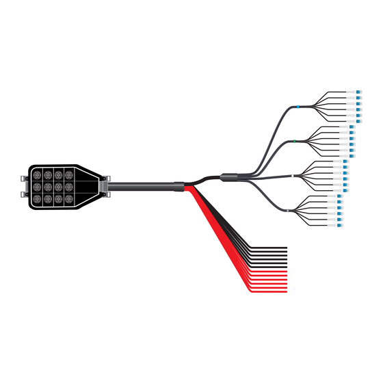
End 2: 12-6 WG or 12-4AWG DC conductors blunt-cut, 48 single mode fibers (24 pairs) terminated FD21204-48SRC-XXX End 2 BBU Power conductors End 1 RRU connectors Cable Assembly HQLC connectors Length (Senko IP25 Plug) DLC connectors with power pins www.commscope.com Bulletin # 7843672 Rev. B... -
Page 4: Section 3: Hoisting Considerations
Installation temperature range is -30 °C to +70 °C (-22 °F to +158 °F). • Maximum cable tensile load can be found on-line in our eCatalog section at www.commscope.com. CommScope Lace-Up Hoisting Grip 29961-C for FD21206 and FD21204 installation. •... - Page 5 Minimum Tie back ropes leader 1 m (3 ft) 5.3 m (17 ft) Clevis Required Hoisting Apply provided Tie grip Wrap to the base of the hoisting grip before applying tension to the line. www.commscope.com Bulletin # 7843672 Rev. B...
- Page 6 Cable will need to be completely uncoiled from the reel to access the BBU Hybrid end. cable line WARNING Cable Protect Hybrid cable bridge from external damage Brennan Tower Dogs Hoist line www.commscope.com Bulletin # 7843672 Rev. B...
-
Page 7: Section 4: Mounting
Technical Publication Section 4: Mounting Pendant allows mounting on poles, H-frames, walls, and other common structures on towers, buildings, etc. Contractor provides appropriate hardware. Top Mount Bracket Requires 2 mounts Bottom Mount Bracket www.commscope.com Bulletin # 7843672 Rev. B... -
Page 8: Section 5: General Specifications: Junpers
1067 mm | 42 in 1067 mm | 42 in Diameter Over Jacket 8 mm | 0.31 in 8 mm | 0.31 in Minimum Bend Radius 8.0 cm | 3.1 in 8.0 cm | 3.1 in www.commscope.com Bulletin # 7843672 Rev. B... - Page 9 End 1: 4 fibers terminated DLC with weatherproofing boot for Nokia AirScale radio with R2CT weather HFT206-4SNOK6-xxx shields and blunt-cut power leads End 2: 4 fibers terminated LC and 2-6AWG conductors terminated at HQLC (Senko IP25 Plug) End 1 RRU End 2 Pendant/Enclosure www.commscope.com Bulletin # 7843672 Rev. B...
- Page 10 Discrete Fiber Jumpers for Nokia AirScale Radios, 6 or 12 single mode fibers, armored DFJ-6S025-xxx End 1: DLC breakout for Nokia systems module DFJ-12S025-xxx (shown) End 2: DLC breakout to enclosure End 1 BBU End 2 Pendant/Enclosure www.commscope.com Bulletin # 7843672 Rev. B...
-
Page 11: Section 6: Hqlc Installation
UV rated cable tie for additional security Warning: The female end of the connector attached to the pendant are not field removable. Do Not attempt to remove with wrench. www.commscope.com Bulletin # 7843672 Rev. B... -
Page 12: Section 8: Fiber Mapping
BBU ends are labeled per sector Bottom Junction Box Radio 0 Radio 1 Radio 2 Radio 3 Optical 1 Optical 2 Optical 1 Optical 2 Optical 1 Optical 2 Optical 1 Optical 2 Gamma Beta Alpha www.commscope.com Bulletin # 7843672 Rev. B... -
Page 13: Section 9: Fe-16148-Ovp-B12 Junction Box Wiring Diagram
Power cords are labeled per sector connected to connected to the green alarm the green alarm The power labels can be lost if the length is significantly reduced during terminal terminal installation. Always re-label conductors before cutting off excess. www.commscope.com Bulletin # 7843672 Rev. B... - Page 14 Alarm wire 30 - 18 AWG supplied by Gamma Beta contractor Alpha Junction Box (bottom view) Hybrid Trunk Ground Wire Alarm Wire Hybrid Fiber Trunk Tails Power 1 1/2 in conduit fitting Circuit Breaker Size Recommendation Pendant Amperage 12 RRU www.commscope.com Bulletin # 7843672 Rev. B...
-
Page 15: Section 10: Breakout Procedure / Dlc Connection Considerations
Caution: Do not try to clean adapter with a standard pipe cleaner. The sleeve inner diameter of DLC adapters is too small. Do not try to clean the adapter with cleaning stick if a connector is mounted in one side. Discard cleaning sticks after each use. Adapter Brush www.commscope.com Bulletin # 7843672 Rev. B... -
Page 16: Section 11: All-In-One Cleaner / Inspecting
Is It Clean Inspect Clean? Clean Connect Abrasive particles (i.e. rock dust) can cause permanent damage to the interface. If interface is scratched it cannot be repaired, it would need to be replaced. www.commscope.com Bulletin # 7843672 Rev. B... -
Page 17: Section 12: Excess Cable Management
Mark cutback length Notch Armor using flush cutter in-line with Kevlar strings Place Rip Cord in Notches' Pull Rip Cord Parallel to Cable (while supporting breakout) Stop at Length Marker Separate Armor www.commscope.com Bulletin # 7843672 Rev. B... - Page 18 Remove Excess Rip Cord Apply Electrical Tape to Protect Breakout NOTE: Remember to slide identifier labels down the power conductors before trimming the cable to it’s final length Cable Splitter tool Seam Ripper Part Number: FA-RCRT-PD www.commscope.com Bulletin # 7843672 Rev. B...
-
Page 19: Section 13: Jacketing Removal Procedure For Universal Grounding
6. Grab lifted edge of jacketing with a pair of pliers and roll on the cable 7. Remove excess adhesive with a piece of emery cloth Scan to view video Earthing Kit UG12158-15B4-T is a universal solution for all trunk cables Note: Only use Tin Plated earthing kits www.commscope.com Bulletin # 7843672 Rev. B... -
Page 20: Section 14: Installation Check List
Hinweis: CommScope lehnt jede Haftung oder Verantwortung für Schäden ab, die aufgrund unsachgemäßer Installation, Überprüfung, Wartung oder Demontage auftreten. Atenção: A CommScope abdica do direito de toda responsabilidade pelos resultados de práticas inadequadas e sem segurança de instalação, inspeção, manutenção ou remoção.
Need help?
Do you have a question about the FD21206-48SRC Series and is the answer not in the manual?
Questions and answers