Advertisement
Quick Links
TC-927-IP
Rev A, Mar 2017
www.commscope.com
Content
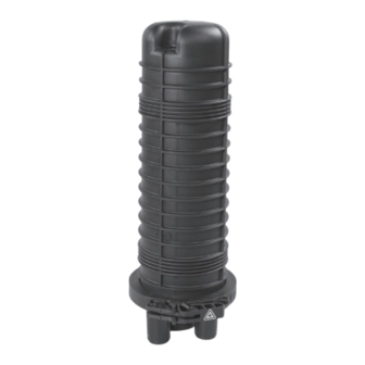
FOSC-400B closure with gel sealing
1 General information
2 Kit content
3 Installation
4 Closing the closure
1
General information
The installation instruction describes the necessary steps to install the FOSC-400BG. The used optical fiber
cables may consist of a loose tube, slotted core, central core or ribbon construction depending on the type
of FOSC kit. Illustrated are the loose tube construction and fusion splicing protected by heat-shrinkable splice
protectors.
The FOSC-400BG can accommodate up to 6 splice tray organizers. One tray can accommodate up to 24
fiber splices.
The closure is a single-ended design made of a thermoplastic material. The base and dome are sealed with a
clamp and an O-ring system. One oval entry port for looped (uncut) cable management and two round ports
for single cable entry/exit are included in the base. Both heat shrinkable cable seals and multi-out cold gel
seals can be used for cable sealing.
The FOSC-400BG can be installed in direct buried, manholes or aerial locations. The kit contents listed in this
installation instruction reflect the standard contents. Alternative configurations are possible.
FOSC-400BG
I N S T A L L A T I O N
I N S T R U C T I O N
Advertisement

Related Manuals for CommScope FOSC-400BG


Summary of Contents for CommScope FOSC-400BG
- Page 1 Both heat shrinkable cable seals and multi-out cold gel seals can be used for cable sealing. The FOSC-400BG can be installed in direct buried, manholes or aerial locations. The kit contents listed in this installation instruction reflect the standard contents. Alternative configurations are possible.
-
Page 2: Kit Content
Kit content Preparation of the oval port 3.2.1 Open the port; the cutting wire can be used. Make sure inner edges are free of burrs! Preparation of the loop cable Make a window cut of 2.60 m, cut strength member at 45 mm. Loop cable mounting •... - Page 3 3.4.3 Feed the loop trough the oval port such that the hose clamps 3.4.5 Lubricate the gel parts and insert the assembly. are ± 5 cm in the port. 3.4.4 Take the first gel part (with trigger) and put the cables in place, if needed (when large cables) lubricate the cables.
- Page 4 3.4.10 Determine the correct length of the transportation tube and fix with 2 tie-wraps to the tray. Knobs at the side! Avoid that the tube is 3.4.7 Make sure that the plastic hooks are flush with the edge of the passing the inner radius of the tray.
- Page 5 3.5.3 Fix the metal bracket as shown. 3.5.6 Feed the cable(s) trough the gel port. Pull back and secure the strength member(s) between the 2 metal plates and fix the cable jacket with the hose clamp as shown.(In case of cables with a soft cable jacket, wrap some foam at the end of the cable jacket).
- Page 6 Closing the closure Position the dome so that the 2 arrows match. Install the cover on the tray and bundle the assembly with the hook and loop fastener as shown. Close of with the clamp. Take the silica gel out of the aluminum packaging and place on top of the tray, attach with some tape.
- Page 8 © 2017 CommScope, Inc. All rights reserved. web at www.commscope.com Fosc and all trademarks identified by ® or ™ are registered trademarks or trademarks, respectively, of CommScope, Inc. For technical assistance, customer service, or to report any This document is for planning purposes only and is not intended to modify or supplement any specifications or warranties relating to missing/damaged parts, visit us at: CommScope products or services.
Need help?
Do you have a question about the FOSC-400BG and is the answer not in the manual?
Questions and answers