Table of Contents
Advertisement
Installation Instructions
TC-96202-IP
Rev C, Aug 2018
www.commscope.com
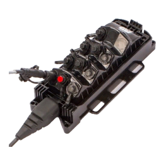
FIBER INDEXING TERMINAL
1.
About this installation instruction
This installation instruction describes the installation of the fiber indexing terminal of both housings, the DLX connector
housing and the full size hardened connector housing, and their different applications: the standard indexing terminal
with splitter (1:4 or 1:8), the indexing only terminal, the branch terminal and the multi-use terminal.
The instruction will explain how to handle the stubbed cable, how to mount the terminal in different situations (hand
hole, pedestal, pole and aerial), how to connect and maintain the different connector types (DLX, full size hardened
connector and HMFOC) and how to test the installed chain of terminals.
660001737
Page 1 of 29
Rev. C
© 2017 CommScope, Inc. All Rights Reserved
Advertisement
Table of Contents

Related Manuals for CommScope FIBER INDEXING TERMINAL


Summary of Contents for CommScope FIBER INDEXING TERMINAL
-
Page 1: About This Installation Instruction
FIBER INDEXING TERMINAL About this installation instruction This installation instruction describes the installation of the fiber indexing terminal of both housings, the DLX connector housing and the full size hardened connector housing, and their different applications: the standard indexing terminal with splitter (1:4 or 1:8), the indexing only terminal, the branch terminal and the multi-use terminal. -
Page 2: Table Of Contents
Visual Fault Locator Lead a single chain of terminals Upstream a position closer to the CO or head end Downstream to a position closer to the end of a lead Page 2 of 29 © 2017 CommScope, Inc. All Rights Reserved... -
Page 3: Fiber Indexing
It allows to build the FTTX network in the outside plant environment faster, with plug and play installation. The exact same components (fiber indexing terminal and the corresponding drops to the homes) are installed between a fiber distribution hub (FDH) and subscribers (homes) in a daisy chain architecture. -
Page 4: Fiber Indexing Terminal
12 fiber cable that enters the terminal through a sealed opening located at the bottom of the terminal. The stub cable is terminated with an HMFOC connector (female). The terminal ships with its UMB. Page 4 of 29 © 2017 CommScope, Inc. All Rights Reserved... -
Page 5: Configurations
12 fiber cable output to the next terminal BLUE HMFOC-branching only 12 fiber cable output that route a portion of the 12 input fibers to another terminal Reverse port Page 5 of 29 © 2017 CommScope, Inc. All Rights Reserved... - Page 6 Reverse port Drop port Reverse port Image below illustrates the positions of the different terminal configurations in the network: INDEXING 1:4 INDEXING 1:8 INDEXING BRANCH SPLITTER ONLY INDEXING ONLY Page 6 of 29 © 2017 CommScope, Inc. All Rights Reserved...
- Page 7 HMFOC taking in the first positions (position 1-9) in the connector. The image below shows the color code and the letter code of the 2 HMFOC adapter ports. HMFOC Adapter port A HMFOC Adapter port B Page 7 of 29 © 2017 CommScope, Inc. All Rights Reserved...
-
Page 8: Cable Stub
Fiber 1 A serial number label is applied on the cable approximately 0.2 m (8 inch) from the connector body. See image below. a1, Fiber 1-12 a2, Fiber 13-24 Page 8 of 29 © 2017 CommScope, Inc. All Rights Reserved... -
Page 9: Universal Mounting Bracket
“P” clamps for self supporting aerial installations. How to use this is explained in chapter 14 maintenance. Cable routing rings or fasteners (see local practices). Cable can be lashed for messenger applications. Page 9 of 29 © 2017 CommScope, Inc. All Rights Reserved... -
Page 10: Installation Overview
For installation, refer to section 11 or 12). 6. Maintenance Maintenance for the indexing terminal is limited to cleaning the hardened adapters as needed to maintain optimal performance. Refer to section14. Page 10 of 29 © 2017 CommScope, Inc. All Rights Reserved... -
Page 11: Cable Handling Recommendations
NESC Medium load Destrict NESC Heavy load Destrict 4. Mount the UMB or NDX-pole-BRKT and secure the cable (for example with a P-clamp attached to a D-ring in aerial applications). Page 11 of 29 © 2017 CommScope, Inc. All Rights Reserved... -
Page 12: Mounting The Terminal
CARSON INDUSTRIES ® Release the terminal and move it slightly upwards. Now the cable end can be taken out of the bracket: CHANNELL ® Page 12 of 29 © 2017 CommScope, Inc. All Rights Reserved... -
Page 13: Pedestal Mounting
HAND-HOLE SWING ARM MOUNT HAND-HOLE LEDGE MOUNT 7-INCH PROFORM ® #10 X 1 INCH SELF TAPPING SCREWS HAND-HOLE HANGER MOUNT 6- OR 8-INCH CHANNELL ® Page 13 of 29 © 2017 CommScope, Inc. All Rights Reserved... -
Page 14: Pole-Mounting
Also metal straps can be used to mount the UMB to a pole, for instance in case of a metal pole. USE SIDE HOLES WHEN SECURING UMB WITH CONSTRUCTION SCREWS #10 X 1 INCH SELF TAPPING SCREWS METAL STRAPS Page 14 of 29 © 2017 CommScope, Inc. All Rights Reserved... -
Page 15: Strand-Mounting
UMB until the latch snaps closed. 2. PUSH ON FRONT OF MST UNTIL LATCH SNAPS SHUT 1. INSERT CABLE END OF MST INTO THE UMB Page 15 of 29 © 2017 CommScope, Inc. All Rights Reserved... -
Page 16: Link Installation (Hmfoc)
Before removing the cable’s con- nector dust cap, clean any debris from around the cable connector housing, preferably using compressed air, to minimize the risk of introducing contaminants onto the ferrule. Page 16 of 29 © 2017 CommScope, Inc. All Rights Reserved... -
Page 17: Disconnecting The Hmfoc
Thread the optical port dust cap into the optical port and tighten until finger tight. 10.5.7. Thread the drop cable connector coupling nut into the drop cable dust cap and tighten until finger tight. Page 17 of 29 © 2017 CommScope, Inc. All Rights Reserved... -
Page 18: Dlx Connector Installation
The dust cap threads into the adapter housing. An O-ring on the dust cap provides a water tight seal when the dust cap is in place. The 216B key tool is required to remove the dust cap. Page 18 of 29 © 2017 CommScope, Inc. All Rights Reserved... -
Page 19: Dlx Specifications
11.4.1.5. Unscrew the coupling nut from the drop cable connector dust cap. (See figure on pg 18). Page 19 of 29 © 2017 CommScope, Inc. All Rights Reserved... -
Page 20: Disconnecting The Drop Cable From The Indexing Terminal (Dlx Connector Housing) Adapter Port
Thread the drop cable connector coupling nut into the drop cable dust cap and tighten until finger tight. ARROW PROTRUSIONS COUPLING NOTE: ORIENT CONNECTOR SO ARROW IS ALIGNED WITH PROTRUSIONS. Page 20 of 29 © 2017 CommScope, Inc. All Rights Reserved... -
Page 21: Full Size Hardened Connector Installation
Latching: Twist-lock secure long term connection. Physical Contact: Angled Polished Contact (APC), standard 8-degree angle Retention Force: 444.8 N (100 lbs) Cable pull when connected: 111.2N (25 lbs) Page 21 of 29 © 2017 CommScope, Inc. All Rights Reserved... -
Page 22: Connecting The Drop Cable To The Indexing Terminal (Full Size Hardened Connector Housing) Adapter Port
Before removing the cable’s con- ORIENT CONNECTOR SO ARROW IS ALIGNED WITH NOTCH COUPLING Page 22 of 29 © 2017 CommScope, Inc. All Rights Reserved... -
Page 23: Disconnecting The Drop Cable From The Indexing Terminal (Full Size Hardened Connector Housing) Adapter Port
* 12th fiber continuity testing relies on all fibers being spliced or connected prior to the first terminal. ** Applies to twelfth link in chain Page 23 of 29 © 2017 CommScope, Inc. All Rights Reserved... - Page 24 If any ports terminal. show light, continuity is confirmed. • Connect a reflective event upstream to the fiber associated with the targeted terminal record test readings. Page 24 of 29 © 2017 CommScope, Inc. All Rights Reserved...
-
Page 25: Bench Testing
Determine status of adjacent terminals • Understand the cable leads and their counts. • Do not disconnect multi fiber connectors until you can physically see its other end or damage. Page 25 of 29 © 2017 CommScope, Inc. All Rights Reserved... -
Page 26: Restoral
Suggest using GATOR splice closure, FDSC-GATOR-12F-T. 13.5. Appendix 13.5.1. HMFOC Fiber map ABS (n-13)= position of first reverse fiber in HMFOC n=terminal position in the chain 13.5.2. Loss Table - MONTE-CARLO Page 26 of 29 © 2017 CommScope, Inc. All Rights Reserved... -
Page 27: Maintenance
14.2.1.9. When the connector and the adapter are clean, install the connector into optical port. 14.1.7. After cleaning, inspect the multi fiber ferrule on adapter and connector side again. Page 27 of 29 © 2017 CommScope, Inc. All Rights Reserved... -
Page 28: Cleaning Full Size Hardened Connector And Adapter
14.3.1.8. Repeat Step 12.4.2.3 through 12.4.2.6 until the connector has been cleaned three times. 14.3.1.9. When the connector and the adapter are clean, install the connector into optical port.. Page 28 of 29 © 2017 CommScope, Inc. All Rights Reserved... -
Page 29: Trademarks
Trademarks REPEAT CLEANING PROCEDURE THREE TIMES USING A CLEAN TAPE CommScope and all other trademarks identified by ® or EACH PASS. RELEASE AND RE-SQUEEZE LEVER TO ADVANCE THE ™ are registered trademarks or trademarks, respectively, TAPE of CommScope, Inc. DIRECTION...
Need help?
Do you have a question about the FIBER INDEXING TERMINAL and is the answer not in the manual?
Questions and answers