Table of Contents
Advertisement
Quick Links
TC-2039-IP
Rev A, Apr 2018
www.commscope.com
Contents
CY6998-000
Rev. D
1
General
1.2 Product description
2
Sizing and product kit
Information
2.1 Dimensions
3
precautions
4
1
General
1.1
Installation Instruction description
The installation instruction describes the necessary steps to install the FOSC-350C.
The installation instruction illustrates the use on loose tube cables. If other cable types (slotted
core or central core) are used, supplementary installation steps have to be made. Contact the
local agent to get the relevant accessories and instructions.
1.2
Product description
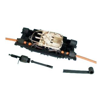
The FOSC-350C in-line closure is a gel-sealed fiber optic splice closure designed for cable joint
applications in the telecom outside plant network. The closure has maximum splicing capacity of
192 splices and is suitable for deployment in aerial, underground or direct buried environments.
Sealing is achieved via built-in gel technology, resulting in extremely convenient re-entry and re-
sealing. The closure has four cable ports, two on both sides.
2
Sizing and product kit information
2.1
Dimensions
Cable diameter range in port
Outer closure dimension
FOSC-350C
I N S T A L L A T I O N
Gel-sealed In-line Fiber Optic Closure
5
6
6.1
6.2
When using Tray 48
7
8
9
8 - 20 mm (8 - 17 mm if using 4x48 tray)
367 x 182 x 106 mm
I N S T R U C T I O N
Advertisement
Table of Contents

Related Manuals for CommScope FOSC-350C


Summary of Contents for CommScope FOSC-350C
-
Page 1: Table Of Contents
Product description The FOSC-350C in-line closure is a gel-sealed fiber optic splice closure designed for cable joint applications in the telecom outside plant network. The closure has maximum splicing capacity of 192 splices and is suitable for deployment in aerial, underground or direct buried environments. -
Page 2: Installation Instruction Description
Kit content 2.3.2 Tray kit –Tray 48 1. Splicing tray (Using Tray 48) 2. Fusion splice protectors 3. Transportation tube 4. Tie Wraps Installation conditions precautions The closures can be installed at temperature between -5°C and 45°C. Standard kit is listed below, alternative kits and accessories are available. Body and cover Follow the installation instruction steps to ensure the Splicing tray with splice holder... - Page 3 Cut the strength member on both jacket ends at a Clean the cable sheath with the cleaning tissue distance of 45 mm from the cable jacket. Note: If a dual strength member is present, cut one of the strength members flush with the jacket end.
- Page 4 4.12 Mark the cable where the blocking rings will be 4.15 At the cable port where the cable will be installed, install installed as shown. Install the rings over the cable with two black tie wraps. the slit positioned under the cable. 4.16 Position cable...
-
Page 5: Cable Installation (Fixed Cable Bracket)
4.19 Install a cable plug (hole towards outside) in all unused Wrap the cable with gel strip. Continue wrapping the closure cable ports. strip smoothly until the area between the two blocking rings is completely filled with gel and add 1 extra turn of gel. In this case, the gel will exceed the diameter of the blocking rings. -
Page 6: Fiber Preparation 6.1 When Using Tray
Make sure the ring tree in the slot and secure the Fiber preparation cable. When using Tray 24 6.1.1 In case of a looped cable, coil the loops and store them in the space in front of the tower of the closure (loops can be stored around the tower as well). - Page 7 6.1.5 Route the transportation tubes to the tray entrance. 6.2.2 Remove the loose tubes up to 100mm from the cable Always route the tubes around the tray tower before entering the jacket end. tray. 6.2.3 Degrease the fiber bundle and slide the transportation tube (length of +/- 230mm) over the fibers until the transportation tube has an overlap with the tube of 50mm.
-
Page 8: When Using Tray 12 (Thin Tray)
6.2.8 Remove/Install tray 48 as following shows Splicing and fiber storage Position the FOSC-350C close to the splicing machine in a convenient location and secure the closure. Slide the heat-shrinkable splice protection over one fiber and fuse fibers according to local recommendations and procedures. - Page 9 Incoming fibers should be routed first behind the splice Put on butterfly tabs and tray lid to secure the fiber if holder before the over-length is coiled into the tray. Route the using 48 trays fibers through the cross of the tray as shown. Secure the trays by the Velcro.
-
Page 10: Closing Of The Closure
Termination in manholes. Secure the closure to the Closing of the closure manhole frames with bolts in the provided positions on the Close the cover by closing the latches in the proper bottom part of the closure. sequence shown in 8.2. Re-opening 10.1 Remove the latches in the reversed order as... - Page 12 © 2018 CommScope, Inc. All rights reserved. web at www.commscope.com SMOUV and all trademarks identified by ® or ™ are registered trademarks or trademarks, respectively, of CommScope, Inc. For technical assistance, customer service, or to report any This document is for planning purposes only and is not intended to modify or supplement any specifications or warranties relating to missing/damaged parts, visit us at: CommScope products or services.
Need help?
Do you have a question about the FOSC-350C and is the answer not in the manual?
Questions and answers