Table of Contents
Advertisement
Quick Links
F573
Rev C, April 2023
www.commscope.com
Contents
1
General product information 1
2
Kit contents 2
3
Other Accessory Kits (Sold separately) 2
4
Warnings and Cautions 2
5
Closure entry 3
6
Base removal 3
7
Cable preparation 3
7.1
Table cable cut length ................................................................................... 4
7.2
Loose Buffer Tube cable ................................................................................ 4
7.3
Ribbon cable .................................................................................................... 4
1
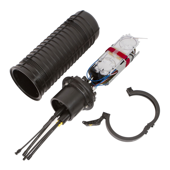
General product information
FOSC450 C and D fiber optic splice closures, use compressed gel cable seals to environmentally seal fiber cable splice points.
Both C and D closures share the same base which allows 6 cable entry ports. Size D however comes with a longer dome
allowing a size-D tray to be used which has more splicing capacity.
Tray type / closure
Number of single height unit splice trays
Number of double height unit splice trays
Number of single splices (stranded fiber) with
SM6 Modules
Number of single splices (stranded fiber) with
SM12 Modules
Number of mass fusion splices using single
height trays for rollable ribbon
Number of mass fusion splices using double
height trays for rollable ribbon or flat matrix
ribbon
Table above shows splicing capacity of FOSC450 C and D closures. Splicing capacity depend on tray type, slack storage
basket, and whether ribbon fibers or stranded are used.
The standard basket is the standard size for buffer tube storage and provides a proportioned balance between splice capacity
and slack storage. For applications requiring more splice capacity, a flexible sock or tray backbone may be used in place of
the basket to maximize splicing capacity. For applications requiring more buffer tube storage, such as mid-span applications,
tall baskets may be used to maximize slack storage.
Splicing trays are either single height or double height. Double height trays are deeper trays allowing storage of flat matrix
ribbon within the tray. Single height trays can be used for flat ribbon, but slack fiber should be pulled back and stored in the
basket and shouldn't be stored within the tray.
FOSC450 C AND D CLOSURES
C Closure
Tall basket
Standard
basket
5
2
60
72
120
144
720
864
432
648
Installation Instructions
8
Cable installation 4
9
Routing fibers to the splice tray 7
10
Gel Block Installation 10
11
Flash Test 13
12
Re-entry 13
13
Adding cables 13
14
Disclaimer 13
15
Contact information 13
No basket
Tall basket
6
8
3
4
96
192
NA
NA
D Closure
Standard
basket
5
6
2
3
180
216
360
432
2160
2592
1152
1728
© 2023 CommScope, Inc. All Rights Reserved
No basket
8
4
288
576
NA
NA
Page 1 of 13
Advertisement
Table of Contents


Need help?
Do you have a question about the FOSC450 C and is the answer not in the manual?
Questions and answers