Table of Contents
Advertisement
Available languages
Available languages
Quick Links
Advertisement
Chapters
Table of Contents

Related Manuals for KNOVA KN M-2509RC


Summary of Contents for KNOVA KN M-2509RC
- Page 1 ” Slide compound miter saw Sierra angular compuesta deslizable KN M-2509RC...
-
Page 2: Table Of Contents
TABLE OF CONTENTS Table of contents .............. Know your slide compound miter saw ....... Product specifications ............Glossary of terms .............. Warnings ................Assembly ................Symbols ................1 Adjustments ..............13 Power tool safety .............. Operation ................17 Compound miter saw safety ..........Maintenance .............. -
Page 3: Power Tool Safety
POWER TOOL SAFETY GENERAL SAFETY INSTRUCTIONS BEFORE USING 14. SECURE WORK. Use clamps or a vise to hold work when practical. It is safer than using your THIS POWER TOOL hand and it frees both hands to operate the tool Safety is a combination of common sense, staying aled and knowing how to use your power tool. -
Page 4: Compound Miter Saw Safety
COMPOUND MITER SAW SAFETY SPECIFIC SAFETY INSTRUCTIONS FOR THIS 22. PROVIDE adequate support to the sides of the saw table COMPOUND MITRE SAW for long work pieces. 1. DO NOT operate the miter saw until it is completely 23. NEVER use the miter saw in an area with flammable assembled and installed according to these instructions. -
Page 5: Electrical Requirements And Safety
ELECTRICAL REQUIREMENTS AND SAFETY POWER SUPPLY AND MOTOR SPECIFICATIONS 4. FUSES may “blow” or circuit breakers may trip frequently if: The AC motor used in this saw is a universal, nonreversible a. MOTOR is overloaded – overloading can occur if you feed too rapidly or make too many start/stops in a short time. -
Page 6: Accessories And Attachments
ACCESSORIES AND ATTACHMENTS RECOMMENDED ACCESSORIES cause tips to crack or break off. Before using, always visually examine the blade and tips for bent blade, WARNING cracks, breakage, missing or loose tips, or other damage. Do not use if damage is suspected. Failure to •... -
Page 7: Carton Contents
To avoid electric shock, use only identical handle. It may cause misalignment. Lift machine by the replacement parts when servicing double insulated tools. hand holds for transportation. Call 01-800-70-KNOVA (56682) for replacement parts. Miter saw Miter handle hardware bag Operator’s manual... -
Page 8: Motor
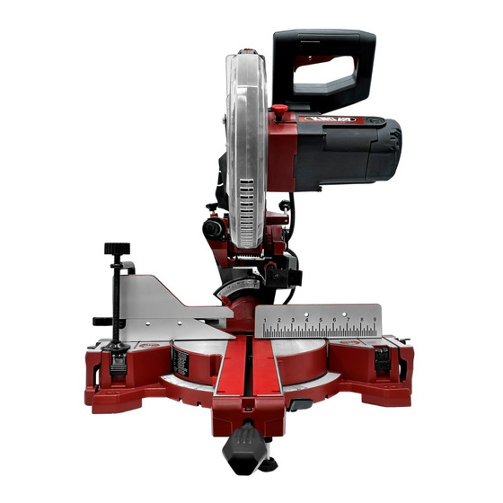
KNOW YOUR SLIDE COMPOUND MITER SAW ON/OFF Laser ON/OFF Trigger switch switch handle Cover plate Slide carriage Motor brush cap lock knob Laser vertical adjustment knob Slide carriage Laser horizontal adjustment knob Bevel locking handle Lower blade guard Hold-down clamp Table Sliding fence Miter detent... -
Page 9: Glossary Of Terms
GLOSSARY OF TERMS AMPERAGE (AMPS) – A measure of the flow of electric POSITIVE STOP LOCKING LEVER – Locks the miter saw current. Higher ratings generally means the tool is suited at a preset positive stop for the desired miter angle. for heavier use. -
Page 10: Assembly
ASSEMBLY WARNING WARNING To avoid injury, do not connect this miter Do not use this saw to cut and/or sand saw to the power source until it is completely metals. The hot chips or sparks may ignite sawdust assembled and adjusted and you have read and un- from the bag material. - Page 11 ASSEMBLY INSTALLING THE HOLD-DOWN CLAMP ASSEMBLY REMOVING AND INSTALLING THE BLADE (FIG. E, F) WARNING • Do not use a blade larger than 10 in. Place the hold-down clamp assembly (1) in one of in diameter. To avoid injury from an accidental start, the mounting holes (2) located behind the fence.
- Page 12 ASSEMBLY 5. Rotate the cover plate (3) and lower blade guard (1) back to its original position. (Fig. H-1) 6. Lower the blade guard and replace the cover plate screw (2) and tighten with a Phillips screwdriver. (Fig H) 7. Pull the main handle down and up several times to confirm the lower blade guard operates without binding.
- Page 13 ASSEMBLY MOUNTING THE MITER SAW (FIG. L, M) 3/4 in. plywood WARNING To avoid injury from unexpected saw movement: • Before moving the saw, disconnect the power cord from the outlet, and lock the cutting arm in the lower position using the head hold-down latch. NOTE: The head hold-down latch is for carrying or storing the tool.
-
Page 14: Adjustments
ADJUSTMENTS BEVEL STOP ADJUSTMENT 45° Bevel Stop Adjustment (Fig. P, Q) 1. Set the miter angle to zero degrees. Fully extend the WARNING To avoid injury from an accidental start, sliding fence completely to the left then pull the bevel make sure the switch is in the OFF position and the detent pin (3) toward the front of the machine. - Page 15 ADJUSTMENTS Adjusting Miter Angles: ADJUSTING CUTTING DEPTH (FIG. T, T-1) The maximum depth travel of the cutting head was set at the 1. Lift up on the quick-cam miter locking lever (1) to unlock factory. the table. Setting the maximum width travel of the cutting head, 2.
- Page 16 ADJUSTMENTS Setting the cutting depth (Fig. T-1): ALIGNING THE LASER GUIDE The depth of cut can be preset for even and repetitive shallow The laser beam must always be correctly aligned with the cuts. blade to ensure straight, even cutting. Your tool is equipped with the Laser Guide cutting guide using Class IIIa laser beam.
- Page 17 ADJUSTMENTS Procedure B (Fig. X, Z) Laser 2. Slightly turn the laser horizontal adjustment knob (2) to Laser warning adjust the horizontal angle of laser beam on the top of the Aperture label board. If the laser beam is out of parallel from left to right, Label turn the laser horizontal adjustment knob (2) clockwise;...
-
Page 18: Operation
ADJUSTMENTS EXTENSION WING USE AND ADJUSTMENT (FIG. AA) The left and right side extension wings can offer extra support for long workpieces. 1. Lift up on the locking lever (1) and pull out the left extension wing to the desired support length. Push down on the locking lever (1) to tighten the extension wing. - Page 19 OPERATION • Make sure the blade is sharp, undamaged and properly INSPECT YOUR WORKPIECE aligned. With the saw unplugged, push the cutting arm all • Make sure there are no nails or foreign objects in the part the way down. Manually spin the blade and check for of the workpiece being cut.
- Page 20 OPERATION WHEN SAW IS RUNNING BASIC SAW OPERATIONS WARNING WARNING Do not allow familiarity from frequent For your convenience, your saw has a use of your miter saw to result in a careless blade brake. The brake is not a safety device. mistake.
- Page 21 OPERATION REMOVING OR INSTALLING THE SLIDING FENCE Fig. FF (FIG. EE) WARNING DRY RUN - It is important to know where the blade will intersect with the workpiece during cutting operations. Always perform a simulated cutting sequence with the power tool switched OFF to gain an understanding of the projected path of the saw blade.
- Page 22 OPERATION 4. To disengage the detent override, pull the quick-cam miter locking lever (1), pull the positive stop locking lever (3) up. This will release the override lock and the table will now stop at the positive detent angles. Fig. HH BEFORE LEAVING THE SAW Fig.
- Page 23 OPERATION 33.9° BEVEL DETENT PIN FOR CROWN MOLDINGS To Slide Cut Wide Boards (Fig. MM) (FIG. KK) 1. Unlock the sliding carriage lock knob (1) and allow the 1. Push the bevel detent pin (1) in toward the rear cutting head assembly to move freely. of the machine.
- Page 24 OPERATION CUTTING GROOVES (FIG. OO) CUTTING BASE MOLDING (FIG. QQ) Base moldings and many other moldings can be cut on a WARNING DO NOT USE A DADO BLADE, use only compound miter saw. The setup of the saw depends on the standard 10 in.
- Page 25 OPERATION NOTE: The chart below references a compound cut for crown molding ONLY WHEN THE ANGLE BETWEEN THE WALLS EQUALS EXACTLY 90°. BEVEL SETTING MITER SETTING TY P E OF C U T Inside corner-Left side 1. Position top of moulding against fence. 33.9º...
- Page 26 OPERATION CROWN MOLDING CHART 52/38” Crown Molding 45/45” Crown Molding 52/38” Crown Molding 45/45” Crown Molding Angle Miter Bevel Miter Bevel Between Angle Setting Setting Setting Setting Miter Bevel Miter Bevel Walls Between Setting Setting Setting Setting Walls 10.34 12.93 11.83 11.59 21.42...
-
Page 27: Maintenance
MAINTENANCE MAINTENANCE SAWDUST Periodically, sawdust will accumulate under the work table DANGER To avoid injury, never put lubricants on and base. This could cause difficulty in the movement of the the blade while it is spinning. worktable when setting up a miter cut. Frequently blow out or vacuum up the sawdust. -
Page 28: Troubleshooting Guide
3. Arbour bolt loose. 3. Retighten. See REMOVING OR INSTALLING THE BLADE section. 4. Brushes cracked, damaged, etc. 4. Replace brushes. 5. Contact Knova Service Centre. 5. Other. 1. Limit switch failure 1. Replace limit switch. Motor does not start. -
Page 29: Parts List
Any attempt to repair or replace electrical parts on this Miter Saw may create a HAZARD un- less repair is done by a qualified service technician. Repair service is available at your nearest Knova Service Centre. PARTS LIST FOR MITER SAW (A) I.D. - Page 30 PARTS LIST PARTS LIST FOR MITER SAW (B) I.D. No. D e s c r i p t i o n S i z e Qty. I.D. No. D e s c r i p t i o n S i z e Qty.
-
Page 31: Diagram Parts
DIAGRAM PARTS KN M-2509RC ” Slide compound miter saw Sierra angular compuesta deslizable... -
Page 32: Parts List And Motor Diagram
PARTS LIST AND MOTOR DIAGRAM PARTS LIST FOR MOTOR I.D. No. D e s c r i p t i o n S i z e Qty. I.D. No. D e s c r i p t i o n S i z e Qty. -
Page 33: Indice
INDICE Indice ................. 32 Conozca su sierra ingletadora compuesta deslizante ..38 Especificaciones del producto ..........32 Glosario de términos ............39 Advertencia ................ 32 Ensamble ................40 Símbolos de seguridad ............32 Ajustes ................44 Seguridad en el manejo de herramientas eléctricas ..33 Operación ................ -
Page 34: Seguridad En El Manejo De Herramientas Eléctricas
SIMBOLOS DE SEGURIDAD MANTENGA LAS MANOS ALEJADAS DE LA HOJA: ADVERTENCIA ADVERTENCIA: Indica una posible El no mantener las manos alejadas de la hoja situación de riesgo que, si no se evita, puede ocasionar puede causar graves lesiones personales. lesiones graves o la muerte. APOYE LA PIEZA DE TRABAJO Y ASEGURELA PRECAUCION PRECAUCION: Indica una posible... -
Page 35: Seguridad Para La Sierra Ingleteadora Compuesta Deslizable
SEGURIDAD EN EL MANEJO DE HERRAMIENTAS ELÉCTRICAS 23. NO USE la herramienta eléctrica en presencia de líquidos PELIGRO 26. Las personas que tienen dispositivos ó gases inflamables. electrónicos, como marcapasos, deben consultar al médico antes de usar este producto. La operación de 24. -
Page 36: Requisitos Eléctricos Y Seguridad
SEGURIDAD PARA LA SIERRA INGLETEADORA COMPUESTA DESLIZABLE 31. Con las sierras ingletadoras, no se deben usar discos de 34. Después de terminar un corte, suelte en interruptor del corte abrasivos. Las cubiertas de las sierras ingletadoras gatillo y permita que la sierra se detenga completamente, no son adecuadas para los discos de corte abrasivos. -
Page 37: Accesorios Y Acoplamientos
ACCESORIOS Aunque las hojas HSS son más baratos que las carburo Visite las tiendas Knova o véase el Catálogo de Herramientas calzado (TCT), la agudeza de las hojas TCT es más larga que Mecánicas y Manuales Knova para comprar los accesorios HSS. -
Page 38: Herramienta Necesaria Para El Montaje
Levante la máquina por los mangos de herramientas de doble aislamiento. LLAME AL transporte incorporados. 01-800-70-KNOVA (56682) para piezas de repuesto. Bolsa de aditamentos Manual para la manija de la Prensa de sujeción... -
Page 39: Conozca Su Sierra Ingletadora Compuesta Deslizante
CONOZCA SU SIERRA INGLETADORA COMPUESTA DESLIZANTE Mango de interruptor de gatillo Interruptor de encendido de ENCENDIDO/APAGADO /apagado del láser Cubreplaca Tapa de cepillo Mango de sujeción del motor del soporte deslizante Perilla para ajuste vertitcal Soporte de laser Deslizante Perilla para ajuste horizontal Orificios de de laser... -
Page 40: Glosario De Términos
GLOSARIO DE TERMINOS AMPERAJE (A) – Es la medición del flujo de corriente TRABA DE RESORTE DE LA MESA DE INGLETES – Traba eléctrica. Las calificaciones más altas generalmente indican la sierra para cortar ingletes en una posición predeterminada, que la herramienta es apropiada para un uso más pesado. para lograr el ángulo de inglete deseado. -
Page 41: Ensamble
ENSAMBLE IMPORTANTE: Revise frecuentemente y vacíe la bolsa antes ADVERTENCIA Para evitar lesiones, no conecte de que se llene. esta sierra para cortar ingletes a la fuente de energía hasta que esté completamente ensamblada ADVERTENCIA Para evitar lesiones, no conecte y ajustada, y hasta haber leído y entendido este esta sierra para cortar ingletes a la fuente de energía Manual del Operador. - Page 42 ENSAMBLE INSTALACIÓN EL ENSAMBLE DE LA ABRAZADERA DE EXTRACCIÓN E INSTALACIÓN DE LA HOJA FIJACIÓN (FIG. E, F) ADVERTENCIA • Use sólo hojas de 25,4 cm de Coloque el ensamble de la abrazadera de fijación (1) en uno diámetro. Para evitar lesiones por incendios de los agujeros de montaje (2) ubicados detrás de la guía.
- Page 43 ENSAMBLE 5. Gire la placa de cubierta (3) y la cubierta inferior de la hoja (1) a su posición original. (Fig. H-1) 6. Baje el cubierta inferior de la hoja y reemplace el tornillo de la placa de cubierta (2) y ajuste el tornillo con un destornillador Phillips.
- Page 44 ENSAMBLE MONTAJE DE LA SIERRA PARA CORTAR INGLETES 2. Para uso portátil, coloque la sierra sobre un pedazo (FIG. L, M) grueso de madera contrachapada de 1,9 cm. Asegure con firmeza la base de la sierra a la madera ADVERTENCIA contrachapada usando los orificios de montaje de la base.
-
Page 45: Ajustes
AJUSTES AJUSTE DE TOPE DE BISEL Ajuste de bisel a 45° (Fig. P, Q) 1. Coloque el ángulo de ingletado a cero grados. Extienda ADVERTENCIA Para evitar lesiones por encendidos totalmente la barra deslizable completamente a la accidentales, asegúrese de que el interruptor esté izquierda, después tire el pasador de retén de biselado (3) hacia la parte frontal de la máquina. - Page 46 AJUSTES Ajuste los ángulos de inglete: AJUSTE DE LA PROFUNDIDAD DE CORTE (FIG. T, T-1) 1. Levante la leva de sujeción rápida de ingletes (1) para El recorrido de máxima profundidad del cabezal de corte se desbloquear la mesa. configuró en fábrica. 2.
- Page 47 AJUSTES Configuración de la profundidad de corte (Fig. T-1): ALINEAMIENTO DE LA GUÍA LÁSER Puede preestablecerse la profundidad de corte para cortes El rayo láser debe estar siempre correctamente alineado con repetitivos uniformes y de poco calado. la hoja para asegurar un corte recto y parejo. Su herramienta está...
- Page 48 AJUSTES Procedimiento B (Fig. X, Z) Etiqueta de Etiqueta de 2. Gire ligeramente la perilla de ajuste horizontal de laser (2) advertencia para ajustar el ángulo horizontal de rayo de laser en la abertura de láser cima de la tabla. Cuando el rayo de laser sea girado del láser desde la izquierda hasta la derecha, gire la perilla de ajuste horizontal de laser (2) en el sentido de aguja del...
-
Page 49: Operación
AJUSTES USO Y AJUSTE DE ALA DE EXTENSION (FIG. AA) Las alas de extension en el lado izquierdo y derecho pueden ofrecer el extra-soporte para las piezas de trabajo largas. 1. Levante arriba en la palanca cerradora (1), y tire afuera la ala de extensión izquierda hasta la longitud apoyada deseada. - Page 50 OPERACIÓN ACCESORIOS RECOMENDADOS UTILICE VESTIMENTA SEGURA • Consulte la sección de ACCESORIOS y Cualquier herramienta eléctrica puede despedir y ACOPLAMIENTOS de este Manual del operador para hacer que se introduzcan en sus ojos objetos obtener información acerca de los accesorios extraños.
- Page 51 OPERACIÓN TENGA EXTREMO CUIDADO CON LAS PIEZAS DE Para comenzar un corte: TRABAJO GRANDES O DE FORMA IRREGULAR • Coloque las manos al menos a 19,05 cm del recorrido de • Use soportes adicionales (mesas, caballetes, bloques, la hoja, fuera de la “zona de manos alejadas” (Véase (1) etc.) para las piezas suficientemente grandes para en Fig.
- Page 52 OPERACIÓN NOTA: El interruptor de ENCENDIDO/ APAGADO ADVERTENCIA La barra deslizable del lado (ON/OFF) debe tener protección de seguridad para los niños. izquierdo se debe retirar al hacer cualquier corte Coloque un candado, o una cadena con un candado, a través de ángulo biselado a la derecha o a la izquierda del orificio (2) del interruptor de gatillo y trábelo para evitar mayor de 33,9°...
- Page 53 OPERACIÓN 3. Gire la mesa al ángulo deseado, asegura la mesa en el Fig. FF ángulo deseado presionando la leva de sujeción rápida de ingletes (1). 4. Para desconectar la anulación del retén, tire la leva de sujeción rápida de ingletes (1), tire la tapa de bloqueo del tope positive del inglete (3) hacia arriba.
- Page 54 OPERACIÓN 6. Abra la guía de laser, y 4. Abra la guía de laser, y ponga la pieza de trabajo en la ponga la pieza de trabajo mesa para pre-alineamiento de corte. en la mesa para pre-alineamiento de corte. PASADOR DE RETÉN PARA BISELADO DE 33,9° PARA MOLDURAS TIPO CORONA (FIG.
- Page 55 OPERACIÓN • Deje que la hoja desarrolle el máximo de velocidad CORTE DE RANURAS (FIG. OO) antes de realizar un corte. Esto ayudará a reducir el ADVERTENCIA riesgo de que la pieza de trabajo salga despedida. NO USE UNA CUCHILLA PARA REDONDEAR, solo use la hoja de sierra estándar de Para realizar cortes deslizantes de tablas anchas (Fig.
- Page 56 OPERACIÓN La mayoría de las molduras de corona tienen un ángulo CORTE DE MOLDURAS DE BASE (FIG. QQ) superior trasero (la sección que encaja perfectamente a tope Las molduras de base y muchas otras molduras pueden contra el techo) de 52° y un ángulo inferior trasero (la sección cortarse con una sierra compuesta para cortar ingletes.
- Page 57 OPERACIÓN CUADRO PARA MOLDURAS DE CORONA Sierra compuesta para cortar ingletes. Configuraciones del ángulo de inglete y de bisel. Angulo de la pared respecto de la moldura de corona. Moldura de corona de 52/38” Moldura de corona de 45/45” Moldura de corona de 52/38” Moldura de corona de 45/45” Angulo Angulo Configuración...
-
Page 58: Mantenimiento
OPERACIÓN TABLA DE MOLDURA DE CORONACION Moldura de corona de 52/38” Moldura de corona de 45/45” Moldura de corona de 52/38” Moldura de corona de 45/45” Angulo Configuración Configuración Configuración Configuración formado por Angulo de bisel de inglete de bisel de inglete Configuración Configuración... -
Page 59: Guía Para La Solución De Problemas
3. El perno del eje está flojo. INSTALACION DE LA HOJA. 4. Las escobillas están partidas, dañadas, etc. 4. Reemplace los cepillos. 5. Contacte al Centro de servicio Knova. 5. Otro. EI motor no 1. El interruptor de límite falla. -
Page 60: Lista De Piezas
PELIGROSO, a menos que la reparación sea efectuada por un técnico de servicio calificado. El servicio DE PIEZAS A de reparaciones está disponible en el centro de servicio Knova más cercano. PARTS LIST FOR MITER SAW (A) No. de ID D e s c r i p c i ó... - Page 61 LISTA DE PIEZAS PARTS LIST FOR MITER SAW (A) No. de ID D e s c r i p c i ó n T a m a ñ o Cant. No. de ID D e s c r i p c i ó n T a m a ñ...
-
Page 62: Diagrama De Partes
DIAGRAMA DE PARTES KN M-2509RC ” Slide compound miter saw Sierra angular compuesta deslizable... -
Page 63: Lista De Piezas Y Diagrama Del Motor
LISTA DE LAS PIEZAS PARTS LIST FOR MITER SAW (B) No. de ID D e s c r i p c i ó n T a m a ñ o Cant. No. de ID D e s c r i p c i ó n T a m a ñ... - Page 64 www.knova.com.mx...
Need help?
Do you have a question about the KN M-2509RC and is the answer not in the manual?
Questions and answers