Table of Contents
Advertisement
Advertisement
Table of Contents

Related Manuals for Prodigit 3350F Series


Summary of Contents for Prodigit 3350F Series
- Page 1 3350F Series High power Electronic Load Operation manual S/N:9003350F04 REV: I...
- Page 2 SAFETY SYMBOLS Direct current (DC) Alternating current (AC) Both direct and alternating Three-phase alternating Protective earth On (Supply) Off (Supply) Fuse Caution!Refer to this manual before using the meter. Caution, risk of electric shock – Is for measurements performed at the source of the low-voltage CAT IV installation.
- Page 3 会也可能不会含有所有所列的部件。This table shows where these substances may be found in the supply chain of Prodigit electronic information products, as of the date of sale of the enclosed product. Note that some of the component types listed above may or may not be a part of the enclosed product. ○:表示该有毒有害物质在该部...
- Page 4 Failure to comply with these precautions or with specific warnings elsewhere in this manual violates safety standards of design, manufacture, and intended use of the instrument. PRODIGIT assumes no liability for the customer's failure to comply with these requirements.
- Page 5 DECLARATION OF CONFORMITY PRODIGIT ELECTRONICS CO., LTD Company Name: 8F, No.88, Baojhong Rd., Sindian City, Taipei County,Taiwan, R.O.C. Address: Declares under sole responsibility that the product as originally delivered DC Electronic Loads Product Names: 3350F、3351F、3352F、3353F、3354F、3356F Model Numbers: (And other customized products based upon the above) Safety and EMC Information: This declaration covers all options and customized products based on the above products.
-
Page 6: Table Of Contents
3350F Series High Power Electronic load operation manual Table of Contents CHAPTER 1 INTRODUCTION........................... 1 1-1.......................... 1 ENERAL DESCRIPTION 1-2............................9 EATURES 1-3............................9 CCESSORIES 1-4..............................9 PTION 1-5............................ 9 PECIFICATIONS CHAPTER 2 INSTALLATION.......................... 12 2-1. - Page 7 5-8...................... 108 OLT LOADING APPLICATION 5-9........................108 ARALLEL OPERATION 5-10. P ......................109 OWER UPPLY TESTING 5-11. P ......................111 OWER UPPLY TESTING 5-12. P SHORT ...................... 113 OWER UPPLY TESTING APPENDIX A GPIB PROGRAMMING EXAMPLE ..................115 APPENDIX B 3350F USB INSTRUCTION .....................
- Page 8 Fig 2-13 Length of wiring ..................... 23 Fig 3-1 3350F-Series High Power Front Panel..............24 Fig 3-2 3350F Series High Power electronic load ..............25 Fig 3-3 Remote sense connection on front panel ..............51 Fig 3-4 an equivalent circuit in terms of the current monitor ..........52 Fig 3-5 (Correct) Connections to an oscilloscope..............
- Page 9 Tables Table 1-1A 3350F Series Specifications ................9 Table 1-1B 3350F Series Specifications ................11 Table 3-1 3350F initialize..................... 65 Table 3-2 3351F initialize..................... 65 Table 3-3 3352F initialize..................... 66 Table 3-4 3353F initialize..................... 66 Table 3-5 3354F initialize..................... 67 Table 3-6 3356F initialize.....................
-
Page 10: Chapter 1 Introduction
3350F Series Operation Manual 1 Chapter 1 Introduction 1-1. General description The 3350F Series Electronic Load is designed to test, evaluation and burn-in of DC power supplies and batteries. The 3350F Series electronic load can be operated for manual and GPIB operation. The power contour of 3350F 1200 Watts Electronic Load is shown in Fig 1-1~1-6, it has an input from 0-120A, and 0 -60V current and voltage operating range respectively. -
Page 11: Fig 1-1 3350F Power Contour
2 PRODIGIT Voltage 1200W CONTOUR Current 20 30 120 A Fig 1-1 3350F Power Contour Voltage 1800W CONTOUR 0.225 0.15 Current 30 40 120 A Fig 1-2 3351F Power Contour... -
Page 12: Fig 1-3 3352F Power Contour
3350F Series Operation Manual 3 Voltage 1200W CONTOUR 0.35 0.23 Current 240 A 20 34.38 60 Fig 1-3 3352F Power Contour Voltage 1800W CONTOUR 0.35 0.175 Current 30 34.38 60 240 A Fig 1-4 3353F Power Contour Voltage 1800W CONTOUR 0.15... -
Page 13: Fig 1-6 3356F Power Contour
Fig 1-6 3356F Power Contour CC Mode: With the operating mode of constant current, the 3350F Series Electronic load will sink a current in accordance with the programmed value regardless of the input voltage (see Fig.1- Fig 1-7 Constant Current mode... - Page 14 3350F Series Operation Manual 5 CR Mode: At constant resistance mode, The 3350F Series Electronic Load will sink a current linearly proportional to the load input voltage in accordance with the programmed resistance setting (see Fig 1-8). LOAD RESISTANCE CURRENT...
- Page 15 6 PRODIGIT CP Mode: At Constant Power mode, the 3350F Series Electronic Load will attempt to sink load power (load voltage x load current) in accordance with the programmed power. (See Fig 1-10). Fig 1-10 Constant Power mode Dynamic wave form definition:...
- Page 16 3350F Series Operation Manual 7 The load current level and load status are can be set with Front panel on each module, GPIB command. It is called manual operation and GPIB operation respectively, the load input voltage and load current can be read back to computer through GPIB.
-
Page 17: Fig 1-12 Rise Time Transition Limitation
8 PRODIGIT Fig 1-12 Rise Time Transition Limitation... -
Page 18: Features
3350F Series Operation Manual 9 1-2. Features 1.2.1. Flexible configuration of high power Electronic Load. 1.2.2. Fully GPIB control of Load condition setting and meter read back. 1.2.3. Dual high accuracy & resolution 5 digit voltage and current meter. 1.2.4. - Page 19 10 PRODIGIT Model 3350F 3351F 3352F 3353F 3354F 3356F Power 1200W 1800W 1200W 1800W 1800W 600W Current 0~120A 0~120A 0~240A 0~240A 0~360A 0~120A Voltage 0~60V 0~60V 0~60V 0~60V 0~60V 0~60V Min. Operating Voltage 0.6V @ 120A 0.4V @ 120A 0.7V @ 240A 0.7V @ 240A...
-
Page 20: Table 1-1B 3350F Series Specifications
3350F Series Operation Manual 11 Ethernet Optional Others Load ON Voltage Range 0.1~25.0V Resolution 0.1V Accuracy 1% of Setting + 0.25V Load OFF Voltage Range 0~25V Resolution Same as Voltage Meter Accuracy Same as Voltage Meter General Short Circuit Current... -
Page 21: Chapter 2 Installation
Prodigit's sales and service office or representative. Your 3350F Series high power load was shipped with a power cord for the type of outlet used at your location. If the appropriated cord was not included, please contact your nearest Prodigit sales office to obtain the correct cord. -
Page 22: Fuse Exchange
3350F Series Operation Manual 13 2-3. Fuse Exchange This product has the power fuse, and exchanges it according to the following procedure. Never fail to turn off the power of this product, and disconnect the plug of the AC Power cable. -
Page 23: Grounding Requirements
2-5. Adjust the feet The 3350F Series high power load is equipped with feet and tilt stands installed and is ready for used as a bench instrument. The feet provide a good viewing angle for bench-top use. -
Page 24: Cleaning
Terminal of the equipment under test. 2-12. Repair If the instrument is damaged, please attach a tag to the instrument to identify the owner and indicated they require service or repairing. And inform the prodigit sales and service office or representative. 2-13. GPIB connection Option The GPIB connector is on the rear panel which to connect the 3350F mainframe to the controller and other GPIB devices. -
Page 25: Rs-232C C
16 PRODIGIT Fig 2-3 3350F series GPIB Rear panel 2-14. RS-232C Connection Option The RS-232C connector (Female) on the rear panel connects 3350F mainframe to RS-232C port of computer in one by one configuration .The RS-232C BAUD-RATE can be set in the front panel, it will be lit the GPIB address when press the “SYSTEM”... -
Page 26: Onnection Ption
3350F Series Operation Manual 17 2-16. LAN Connection Option Fig 2-6 shows the LAN connector in the rear panel of 3350F mainframe. Please refer Appendix C. Fig 2-6 3350F LAN Connection 2-17. GPIB & RS232 connection 2.17.1. GPIB + RS-232C connector is on the rear panel of 3350F mainframe for Application GPIB or RS-232 C. -
Page 27: Nalog Programming Erminal Input
The slew rate determines a rate at which the current changes to a new programmed value. The slew rate can be set at the front panel or via GPIB on the rear panel of 3350F Series high power load. -
Page 28: Fig 2-9 The Relationship Of Load Current Load On/Off, Load Level And Output Voltage Of Dc
3350F Series Operation Manual 19 supply testing task by using Constant current mode only, it can significantly improve the testing quality and process as well as efficiency. There are two load current range in 3350F Load, Range I and Range II, the slew rate of range I, range II, RISE/FALL slew rate are listed in chapter 1-5 specifications.5. -
Page 29: Mergency Stop And Larm
20 PRODIGIT 2-20. Emergency stop and Alarm 3350F series electronic load provided emergency stop signal input and alarm signals output interface on the Rear panel, connector to be D-sub25 Pin female port, Emergency stop signal and Alarm signal are isolated. -
Page 30: Load Wire Inductance
Generates a large voltage at both ends of the wiring cable. This voltage applies to all of the Load input terminals of the 3350F series when the impedance of the EUT is relatively small. The voltage generated by the load wire inductance (L) and the current variation (I) is Expressed using the following equation. -
Page 31: Fig 2-12 Waveform Example: Generate Unstable Oscillation
22 PRODIGIT In such event, the electronic load (3350F) may generate unstable oscillation. In such condition, the input voltage may exceed the maximum input voltage and Cause Damage to the 3350F Series. Current △ I △ Voltage at Load Input Terminal... -
Page 32: Fig 2-13 Length Of Wiring
3350F Series Operation Manual 23 To prevent problems, connect the 3350F series and the equipment under test using the Shortest Twisted Wire possible to keep the voltage caused by inductance between the Minimum operating Voltage and the maximum input voltage range or set a low slew rate. -
Page 33: Chapter 3 Operation
24 PRODIGIT Chapter 3 Operation This chapter describes the front panel function and operation of each 3350F Series load, the memory Store/Recall, GPIB/RS-232/LAN/USB remote programming are described in the mainframe operation manual. Please refer to the mainframe's operation manual for mainframe store/recall and GPIB/RS-232/LAN/USB programming. -
Page 34: Operating Instructions
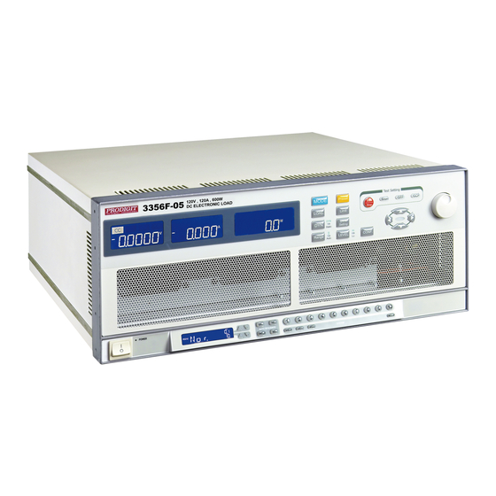
3350F Series Operation Manual 25 Fig 3-2 3350F Series High Power electronic load 3-2. Operating instructions 3.2.1. 3354F 60V/360A,1200W DC ELECTRONIC LOAD It indicates the model number and specifications of 3350F electronic load. 3.2.2. Indicator The user can adjust upper and lower limits for voltage, current and power within the CONFIG menu and turn the NG Indicator ON. - Page 35 26 PRODIGIT 3.2.5. Left 5 digit LCD display The 5 digit LCD display is a multi-function display. The function of the display Changes depending whether the user is in NORMAL mode or in a SHORT, OPP or OCP test modes: Normal mode: The left 5 digit display displays the voltage present at the load’s input terminals.
- Page 36 3350F Series Operation Manual 27 3.2.7. Right 5 digit LCD display The right 5 digit displays also changes function depending if the unit is in normal mode or one of the setting menus has been activated. Normal mode: In normal mode the lower 5 digit display shows the power consumption in Watts (W).
- Page 37 28 PRODIGIT 3.2.7.4. CONFIG. Each press of the CONFIG button changes the middle LCD Text. The sequence and the corresponding setting value shown on the bottom Display are as follows: SENSE can be set to「AUTO」or 「ON」 LDon (load ON voltage) displays the set value in volts “V”...
- Page 38 The appropriate LCD will illuminate according to the operating mode is selected. LOAD 3.2.9. Key and LED The input to the 3350F series Electronic Load can be switched ON/OFF by using The “LOAD” button. Indication of the ON/OFF state is provided by illumination of The button. LOAD button lit...
- Page 39 3.2.11. Key and LED The 3350F series Load Module features 2 setting ranges for CC, CR, CV & CP Operation. This allows improved resolution for setting low values. When left in the Default AUTO mode the changeover between ranges is automatic depending on The setting value entered.
- Page 40 3350F Series Operation Manual 31 P.S Automatically Push Function Level setting, Level High must be higher or equal than Level Low; When Level High equal to than LEVEL Low, it can not be adjusted anymore. When Level High equals to lower low, the Automatic push function can push Down the level Low value.
- Page 41 32 PRODIGIT Limit 3.2.14. Key and LED The LIMIT button allows the user to set upper and lower thresholds for voltage, Current or power. These threshold settings are used in conjunction with the NG Function to flag when the load is operating outside the desired limits Each press of the LIMIT key enables a different value to be entered.
- Page 42 3350F Series Operation Manual 33 Setting Upper limit voltage VH , Middle 5 digit LCD display「V-Hi」,right 5 digit LCD Display the unit is "V”, The V-Hi set range from 0.000 V to 60.000V step 0.001V by Rotating the Setting knob.
- Page 43 34 PRODIGIT Setting Upper limit power WH, Middle 5 digit LCD display「W-Hi」right 5 digit LCD Display the unit is "W", The W-Hi set range from 0.0 W to 1800.0W step 0.1W by Rotating the Setting knob. Setting lower limit power WL, Middle 5 digit LCD display「W-Lo」lower 5 digit LCD Display the unit is "W", The W-Lo set range from 0.0 W to 1800.0W step 0.1W by...
- Page 44 3350F Series Operation Manual 35 CC Dynamic Mode, press key to set the Level Hi and Level Low voltage upper and lower limits of the GO / NG. Current Level Hi Level Low Voltage High CR mode, press limits key to set the V-Hi and V-Lo voltage upper and lower limits of the GO / NG.
- Page 45 36 PRODIGIT CP mode, press limits key to set the W-Hi and W-Lo power upper and lower limits of the GO / NG. Load Current High POWER Voltage setting 3.2.15. Key and LED The DYN button allows the user to define the timings of the dynamic load Waveform.
- Page 46 3350F Series Operation Manual 37 Press DYN setting key, LED will ON Setting level High Period, Middle 5 digit LCD Display will show 「T-Hi」right 5 digit LCD display will show setting value, the unit Is “ms” , The T-Hi Set range from 0.050 ms to 9999 ms step 0.001ms by rotating the Setting Knob.
- Page 47 38 PRODIGIT Setting rise time, Middle 5 digit LCD display will show 「RISE」, right 5 digit LCD Display will show setting value, the unit is “A/µs”, The RISE time set range from 0.024 A/us to 1.53 A/us step 0.006 A/us by rotating the Setting knob.
- Page 48 3350F Series Operation Manual 39 Note 1: The adjustable LDon (LOAD ON) voltage is valid for CC, CR & CP operating Modes. The adjusted LDon voltage will not operate in CV mode. Note 2: The LDon (LOAD ON) voltage setting cannot be lower than the LDoff (LOAD OFF) voltage.
- Page 49 40 PRODIGIT Setting Vsense and load input switching methods, the middle of the 5 digit LCD Display will show "SENSE", right 5 digit LCD display will show "AUTO" or "ON". Set Load ON voltage, the middle of the 5 digit LCD display will show "LDon", right 5 Digit LCD display will show setting value, the units is V, The Load ON Voltage set Range from 0.1V to 25.0V step 0.1V by rotating the setting knob.
- Page 50 3350F Series Operation Manual 41 Short 3.2.17. Key and LED The SHORT key allows the parameters of a SHORT circuit test to be entered. The SHORT test will attempt to sink high current up to the 3350F load maximum Current in order to check the power source’s protection and behavior. The test time can be adjusted and threshold values for the high and low voltage limits set.
- Page 51 42 PRODIGIT Setting the short test time,The LCD display show 「SHORT」 on left 5 digits LCD display,shows 「TIME」on middle 5 digits LCD display,right 5 digit LCD display 「CONTI」, the unit is "ms". TIME: setting the short test time, The LCD display show 「SHORT」 on left 5 digits LCD display, shows 「TIME」on middle 5 digits LCD display the unit is...
- Page 52 3350F Series Operation Manual 43 V-Lo : Short test voltage check lower limitation setting, The LCD display shows 「 SHORT」on left 5 digit LCD display, Middle 5 digit LCD display「V-Lo」,right 5 Digit LCD display setting value, the unit is "V", the V-Hi setting range from 0.000V to 60.000V step 0.001V by rotating the setting knob.
- Page 53 44 PRODIGIT ISTAR: setting the start current point, The LCD display shows 「OCP」on left 5 digit LCD display, Middle 5 digit LCD display「ISTAR」,right 5 digit LCD display Setting value, the unit is "A". The setting range is 0.00A to the full scale of the CC mode specification. The setting Is by rotating the setting knob.
- Page 54 3350F Series Operation Manual 45 ISTOP: setting the stop current point, The LCD display shows 「OCP」on left 5 digit LCD display, Middle 5 digit LCD display「ISTOP」,right 5 digit LCD display Setting value, the unit is "A", the setting range is 0.00A to the full scale of the CC Mode specification.
- Page 55 46 PRODIGIT 3.2.19. Key and LED The OPP key allows the parameters of an Over Power Protection test to be Entered. The OPP test will ramp up the load power in steps to validate the Device Under Test’s (DUT) protection and behavior. A voltage threshold level can be set.
- Page 56 3350F Series Operation Manual 47 PSTAR: setting the start power, The LCD display shows 「OPP」on left 5 digit LCD display, Middle 5 digit LCD display「PSTAR」,right 5 digit LCD display setting Value, the unit is "W", the setting range is 0.0W to the full scale of the CP mode Specification.
- Page 57 48 PRODIGIT PSTOP: setting the stop power, The LCD display shows 「OPP」on left 5 digit LCD display, Middle 5 digit LCD display「PSTOP」,right 5 digit LCD display setting Value, the unit is "W", the setting range is 0.0W to the full scale of the CP mode Specification.
- Page 58 3350F Series Operation Manual 49 3.2.20. The red START/STOP key is used in conjunction with the SHORT, OCP or OPP test functions. It is used to START a test according to the set parameters or to STOP a test before PASS or FAIL is signaled. Please refer to the preceding sections for more information on the SHORT, OCP &...
- Page 59 3.2.23. V-sense input terminal The V-sense terminals can be used to compensate for a voltage drop in the load Lines between the power supply and the 3350F series Electronic Load. This is a useful feature useful when the load current is relatively high.
-
Page 60: Fig 3-3 Remote Sense Connection On Front Panel
3350F Series Operation Manual 51 In the CONFIG menu the V-sense function can be set to AUTO or ON. Please note that if V-sense is set to AUTO and the sense leads are connected to The DUT the losses need to be approx. 700mV (3350F) before the display compensates for the voltage loss. -
Page 61: Fig 3-4 An Equivalent Circuit In Terms Of The Current Monitor
52 PRODIGIT Drain Load+ Gate MOSFET_Nch source Power Supply Ref_V Shunt R Load- IMonitor Fig 3-4 an equivalent circuit in terms of the current monitor Connecting the I-monitor to an oscilloscope When you connect this product to an oscilloscope, please ensure the correct polarities of the Connecting probes as shown in Fig. -
Page 62: Fig 3-6 (Wrong) Connections To An Oscilloscope
3350F Series Operation Manual 53 Fig 3-6 (Wrong) Connections to an oscilloscope If the probes connection is reversed as shown in Fig 3-6, a large current would flow through the Probe and the internal circuitry of the oscilloscope is likely to be damaged. -
Page 63: Front Panel Description (2)
54 PRODIGIT 3-3. Front panel description (2) The mainframe’s LCD will illuminate fully at mains power ON. 3.3.1. REMOTE mode The REM will be lit when 3350F is being controlled via the GPIB/RS232/USB or LAN -Interface. To bring back the unit to front panel control the local button on the Right hand side of the mainframe can be pressed. - Page 64 3350F Series Operation Manual 55 3.3.5. LAN Card The LCD will permanently show LAN if this computer interface has been fitted. 3.3.6. 3350F Main Display 3.3.7. BANK/T1 Display The upper digits on the right hand side of the screen relate to the memory BANK in Normal mode.
-
Page 65: Front Panel Description (3)
56 PRODIGIT 3-4. Front panel description (3) This section briefly describes the buttons on the right hand side of the mainframe. Their Functional use is further described in section 3.4. 3.4.1. The 4 buttons marked exit, test, enter and edit are used to set an auto-sequence. -
Page 66: Operating Instructions
3350F Series Operation Manual 57 3-5. Operating Instructions 3.5.1. Setting System Parameters The system button allows the setting of: GPIB address RS232 BAUD RATE Buzzer ON/OFF 3.5.1.1. To set the GPIB address you must press the system key once. The LCD will Display the current address. - Page 67 Store. 3.5.2. STORE/RECALL Operation The function keys on the front panel of 3350F series electronic load, 3350F STORE/RECALL Ten electronic load STATE Setting items and 15 BANK a total of 150 electronic load state set, each state can store a variety of electronic load status And settings.
- Page 68 3350F Series Operation Manual 59 3.5.3. WAKE-UP Function The wake up function is designed to automatically recall a setting at mains power on. Step 1 Press WAKE UP once or twice so that message SET is displayed on the 3350F LCD.
- Page 69 60 PRODIGIT 3.5.4. AUTO-SEQUENCE An auto-sequence allows the user to step through previously saved set-ups stored in The mainframe’s memory. Up to 9 auto-sequences can be saved. Each auto- Sequence can consist of up to 16 steps. There are two modes in the auto-sequence Function.
- Page 70 3350F Series Operation Manual 61 3. Press ENTER to set the next setting step. Repeat the same Process for each Setting steps. Up to 16 steps can be entered. Once the T1 and T2 settings have been entered for the final Step press the STORE button.
-
Page 71: Fig 3-7 Edit Mode Operation Flow Chart
62 PRODIGIT Press EDIT Key EDIT MODE Press STATE 1~9 Select F1~F9 SET BANK/STATE ENTER SET T1/T2 ENTER NEXT STEP EXIT STORE Fig 3-7 EDIT MODE OPERATION FLOW CHART 3.5.4.2 Test Mode 1. Pressing the TEST button will cause the TEST switch to Illuminate and the LCD to show the last selected Auto-sequence number (F1 to F9). - Page 72 3350F Series Operation Manual 63 Example 1: Once the editing of the 16 step test is completed, press the TEST key. The unit Will then automatically run through the test steps S01 to S16 in order. If all tests Steps have been completed then the LCD will show PASS.
-
Page 73: Fig 3-8 Test Mode Operation Flow-Chart
64 PRODIGIT TEST MODE 1.Press TEST key Show Fx Initial = F1 2.Press STATE 1~9 Select F1-F9 ENTER 3.Press ENTER Exit START TEST Recall correspond memory which had been stored in F1-F9 memory Normal Mode Testing(T1) Check the GO/NG indicator... -
Page 74: Initial Setting Of 3350F Series Load Module
3-6. Initial setting of 3350F series load module When you receive the 3350F series electronic load, the load value initial setting after power ON is listed in table 3-1 ~ table 3-6 respectively, this is the factory or initial setting. -
Page 75: Table 3-3 3352F Initialize
66 PRODIGIT Item Initial value Item Initial value CC L+Preset 0.000 A V_Hi 60.000 V CC H+Preset 0.000 A V_Lo 0.000 V CR H+Preset 15000 Ω I_Hi 240.00 A LIMIT CR L+Preset 15000 Ω I_Lo 0.00 A CV H+Preset 60.000 V W_Hi 1200.0 W... -
Page 76: Table 3-5 3354F Initialize
3350F Series Operation Manual 67 Item Initial value Item Initial value CC L+Preset 0.000 A V_Hi 60.000 V CC H+Preset 0.000 A V_Lo 0.000 V CR H+Preset 10020 Ω I_Hi 360.00 A LIMIT CR L+Preset 10020 Ω I_Lo 0.00 A CV H+Preset 60.000 V... -
Page 77: Input Binding Post And Wire Consideration
68 PRODIGIT 3-7. Input binding post and wire consideration The five ways connect the input wires to the Electronic load the connection methods are Made as follow: 3.7.1. Plug connectors: This is the most popular way to connect the input of Electronic load to the device under test. -
Page 78: Load Current Course/Fine Increase/Decrease Adjustment Knob
3350F Series Operation Manual 69 3-8. Load current course/fine increase/decrease adjustment knob Change amount that CC/CR/CV/CP MODE (CR contrary) load current adjusts form 3-6 shows Analyzes one degree of relations with knobing. Push the knob when operate (the figure will... - Page 79 70 PRODIGIT RANGE I RANGE II 3352F FULL SCALE LOAD 240 A CURRENT 0~24A/240A CURRENT RANGE 0.4m A/4mA METER RESOLUTION COURSE/FINE LOAD CURRENT ADJUSTMENT knob 100mA 10mA 0.8mA 100mA 10mA CC Mode 6.6mS 0.66mS 0.066mS 0.41mΩ 0.041mΩ 0.0041mΩ CR Mode 0.01V...
-
Page 80: Table 3-7 The Resolution Of Range I/Ii Vs. Course/Fine Load Setting Key
3350F Series Operation Manual 71 RANGE I RANGE II 3354F FULL SCALE LOAD 360 A CURRENT 0~36A/360A CURRENT RANGE 0.6mA/6mA METER RESOLUTION COURSE/FINE LOAD CURRENT ADJUSTMENT knob 100.2mA 10.2mA 0.6mA 1000.2mA 100.2mA 10.2mA CC Mode 10mS 0.1mS 0.27mΩ 0.027mΩ 0.0027mΩ... -
Page 81: Protection Features
When the Over power condition is occurred, the Digital Current Meter's LCD display will indicate “OPP ". As soon as the temperature of 3350F Series heat sink greater than 85 degree, the Over temperature protection is occurred, the Digital Current Meter's LCD display will indicate “OTP “at same time, the 3350F Series Electronic Load will turn load to OFF state internally. -
Page 82: Chapter 4 Remote Control Programming Operation
The rear panel remote control interface of 3350F mainframe is designed to connect PC or NOTEBOOK PC with remote control interface, the NOTEBOOK PC acts as a remote controller of 3350F series Electronic Load. This feature can be used as an automatic load/cross load regulation and centering voltage testing for a switching power supply or an rechargeable battery charge/discharge characteristic testing. -
Page 83: 3350F Remote Control Command List1
74 PRODIGIT 4-3. 3350F REMOTE CONTROL COMMAND LIST1 SIMPLE TYPE FORMAT REMARK SETTING PRESET NUMERIC COMMAND RISE{SP} {NR2} {;NL} (m)A/us FALL{SP}{;NL} (m)A/us PERD:{HIGH LOW} {SP} {NR2} {;NL} LDONV{SP} {NR2} {;NL} LDOFFV{SP} {NR2} {;NL} CC CURR:{HIGH LOW} {SP} {NR2}{;NL} CP:{HIGH LOW} {SP} {NR2}{;NL} CR RES:{HIGH LOW} {SP} {NR2}{;NL}... -
Page 84: Table 4-2 Remote Control Query Command Summary
3350F Series Operation Manual 75 QUERY RETURN PRESET NUMERIC COMMAND RISE{?} {;NL} ###.#### FALL{?}{;NL} ###.#### PERD:{HIGH LOW}{?} {;NL} ###.#### LDONV{?}{;NL} ###.#### LDOFFV{?}{;NL} ###.#### CC CURR:{HIGH LOW} {?} {;NL} ###.#### CP:{HIGH LOW} {?} {;NL} ###.#### CR RES:{HIGH LOW} {?} {;NL} ###.#### CV VOLT:{HIGH LOW} {?} {;NL}... -
Page 85: Table 4-4 Stage Command Summary
76 PRODIGIT STAGE COMMAND REMARK LOAD {SP}{ON│OFF│1│0} {;│NL} LOAD {?} {;│NL} 0:OFF 1:ON MODE {SP} {CC│CR│CV│CP} {;NL} MODE {?} {;│NL} 0:CC 1:CR 2:CV 3:CP SHOR {SP} {ON│OFF│1│0} {;│NL} SHOR {?} {;│NL} 0:OFF 1:ON PRES {SP} {ON│OFF│1│0} {;│NL} PRES {?} {;│NL} 0:OFF 1:ON... -
Page 86: Table 4-5 System Command Summary
3350F Series Operation Manual 77 System command:Available for all module. COMMAND NOTE RETURN CHAN {SP} {1 2} {;NL} {1 2} CHAN {?}{;NL} RECALL {SP} {m [,n] }{;NL} m=1~10 n=1~15 m:STATE , n:BANK STORE {SP} {m [,n] }{;NL} m=1~10 n=1~15 m:STATE , n:BANK RS232/USB/LAN REMOTE {;NL}... -
Page 87: Table 4-7 Auto Sequence Command List
78 PRODIGIT AUTO SEQUENCE: Available for all modules. AUTO SEQUENCE SET COMMAND NOTE RETURN FILE {SP} {n}{; NL} n=1~9 STEP {SP} {n} {;NL} n=1~16 1~16 TOTSTEP {SP} {n}{;NL} Total step n=1~16 1~16 SB {SP} {m,n} {;NL} m=1~10 n=1~15 m:STATE , n:BANK T1 {SP} {NR2} {;NL}... -
Page 88: Table 4-1B Remote Control Setting Command Summary
3350F Series Operation Manual 79 3350F REMOTE CONTROL COMMAND LIST2 COMPLEX TYPE FORMAT SETTING COMMAND SUMMARY REMARK [PRESet:] RISE{SP} {NR2} {;NL} (m)A/us [PRESet:] FALL{SP}{;NL} (m)A/us [PRESet:] PERI PERD:HIGH LOW {SP} {NR2} {;NL} [PRESet:] LDONv{SP} {NR2} {;NL} [PRESet:] LDOFfv{SP} {NR2} {;NL} [PRESet:] CCCURR:{HIGH LOW} {SP}... -
Page 89: Table 4-2B Remote Control Query Command Summary
80 PRODIGIT QUERY COMMAND SUMMARY RETURN [PRESet:] RISE {?} {;NL} ###.#### [PRESet:] FALL {?}{;NL} ###.#### [PRESet:] PERI PERD:{HIGH LOW}{?} {;NL} ###.#### [PRESet:] LDONv {?}{;NL} ###.#### [PRESet:] LDOFfv {?}{;NL} ###.#### [PRESet:] CCCURR:{HIGH LOW} {?} {;NL} ###.#### [PRESet:] CP:{HIGH LOW} {?} {;NL} ###.####... -
Page 90: Table 4-4B Stage Command Summary
3350F Series Operation Manual 81 STAGE COMMAND REMARK [STATe:] LOAD {SP}{ON│OFF} {;│NL} [STATe:] LOAD {?} {;│NL} 0:OFF 1:ON [STATe:] MODE {SP} {CC│CR│CV│CP} {;NL} [STATe:] MODE {?} {;│NL} 0|1|2|3:CC|CR|CV|CP [STATe:] SHORt {SP} {ON│OFF} {;│NL} [STATe:] SHORt {?} {;│NL} 0:OFF 1:ON [STATe:] PRESet {SP} {ON│OFF} {;│NL} [STATe:] PRESet {?} {;│NL}... -
Page 91: Table 4-6B Measure Command Summary
82 PRODIGIT Measure command: available for all module COMMAND RETURN MEASure:CURRent{?}{;NL} ###.#### MEASure:VOLTage{?}{;NL} ###.#### MEASure:POWer{?}{;NL} ###.#### Table 4-6B MEASURE COMMAND SUMMARY REMARK : 1. Current engineering unit: A 2. Voltage engineering unit: V 3. Period engineering unit: mS 4. Slew-rate engineering unit: (m)A/uS 5. -
Page 92: The Description Of Abbreviation
3350F Series Operation Manual 83 4-4. The description of abbreviation SP:Space, the ASCII code is 20 Hexadecimal. ;:Semicolon, Program line terminator, the ASCII code is OA Hexadecimal. NL:New line, Program line terminator, the ASCII code is OA Hexadecimal. NR2:Digits with decimal point. It can be accepted in the range and format of###.#####. -
Page 93: Remote Control Command Description
84 PRODIGIT 4-6. Remote control command description 4.6.1. PRESET Set and Read the Default of Load RISE Syntax : [ PRESet:] RISE {SP}{NR2}{;NL} [ PRESet:] RISE ? {;NL} Purpose: Set and read the RISE SLEW-RATE Description: 1. The definition of RISE SLEW-RATE is load level change or dynamic load can be programmed of RISE and FALL are completely independent. - Page 94 3350F Series Operation Manual 85 LDOFfv Syntax: [ PRESet:] LDOFfv{SP}{ NR2}{;NL} [ PRESet:] LDOFfv ?{;NL} Purpose:Set and read the voltage of LOAD OFF Description:This command is for setting the Load voltage value of LOAD OFF. CURR:HIGHLOW Syntax:[ PRESet:] CCCURR:HIGHLOW{SP}{ NR2}{;NL} [ PRESet:] CCCURR:HIGHLOW ?{;NL}...
- Page 95 86 PRODIGIT 2. The least significant number is the 5th behind the decimal point. 3. 3350F will set to the maximum value of the model automatically when the value of Voltage which has been set is over the specification of Load.
- Page 96 3350F Series Operation Manual 87 OPP: STOP Syntax: [PRESet:] OPP:STOP {SP}{NR2}{;NL} [PRESet:] OPP:STOP ? {;NL} Purpose:Set and read the maximum value of OPP test Description:This command is used for setting the maximum value (P-STOP) of OPP test TCONFIG Syntax: [PRESet:] TONFIG {NORMAL|OCP|OVP|OPP|SHORT}{;NL} [PRESet:] TONFIG ?...
- Page 97 88 PRODIGIT [LIMit:]POWer:{HIGHLOW} or WHWL Syntax: [LIMit]:POWer:{ HIGHLOW}{SP}{ NR2 }{;NL} [LIMit]:POWer:{ HIGHLOW} ?{;NL} [WHWL]{SP}{ NR2 }{;NL} [WHWL]?{;NL} Purpose:To set the upper/lower limit value of threshold power (W). Description:This command is to set the upper/lower limit value of threshold power (WATT). When power (WATT) is lower than this lower limit value or higher than the upper limit value, NG indicating light will come on to indicate〝NO GOOD〞.
-
Page 98: Table 4-9 Module For Each Series
3350F Series Operation Manual 89 4.6.3. STAGE Set and read the status of Load [STATe:] LOAD {SP}{ONOFF} Syntax: [STATe:] LOAD{SP}{ONOFF}{;NL} [STATe:] LOAD ?{;NL} Purpose:Set and read the status of Sink Current or not Description:This command is used for setting the status of Sink Current . When setting it to ON, the Load is going to sink current from appliance. - Page 99 90 PRODIGIT [STATe:] SENSe{SP}{ONOFFAUTO} Syntax: [STATe:] SENSe{SP}{ONOFFAUTO }{;NL} [STATe:] SENSe ? {;NL} Purpose:Set and read the Load voltage to read whether is carried by the VSENSE or not. Description:This command is for setting the Load voltage to read whether is carried by VSENSE or INPUT Connector.
-
Page 100: Table 4-10 Register Of Prot Status
3350F Series Operation Manual 91 [STATe:] PROTect? Syntax: [ STATe:] PROTect?{;NL} Purpose:Query if there have protection flag which had been set in this 3350F Description:1.PROT? means the status of Protection of 3350F. “1” means OPP occurred.”4”means OVP. “8” means OCP. Table 4-10 shows the corresponding number of protection status 2.Use command CLR to clear the register of PROT status to be “0”... - Page 101 92 PRODIGIT 4.6.4. SYSTEM Set and Read the Status of 3350F [SYStem:] RECall{ SP }m{ ,n } Syntax:[ SYStem:] RECall{ SP }m{ ,n }{;NL} Purpose: Recall the status of Loading which had been saved in the Memory Description: This command is for recalling the status of Load which had been saved in the Memory .
-
Page 102: Table 4-11 Model Number
3350F Series Operation Manual 93 [SYStem:] NAME? Syntax:[SYStem:] NAME?{;NL} Use : Read the model number of Load State : This command is for reading the model number of Load. it will be lit the model number as table 4-11 :... - Page 103 94 PRODIGIT 4.6.5. MEASURE Measure the actual current and voltage value of Load MEASure:CURRent? Syntax:MEASure:CURRent?{;NL} Purpose:Read the current which is loading of Load Description:Read the five numbers of current meter, and the unit is Ampere(A) MEASure:VOLTage? Syntax:MEASure:VOLTage?{;NL} Purpose:Read the voltage which is loading of Load Description:Read the five numbers of current meter, and the unit is Voltage(V)
-
Page 104: Chapter 5 Applications
3350F Series Operation Manual 95 Chapter 5 Applications This chapter describes the application information of 3350F Series Electronic Load. 5-1. Local sense connections Fig 5-1 illustrates a typical set up with the electronic load connected to the DC power supply. -
Page 105: Remote Sense Connections
96 PRODIGIT 5-2. Remote sense connections Fig 5-2 illustrates a typical set up with the electronic load connected for remote sense operation. The remote Vsense cables of the electronic load are connected to the output of the power supply. Remote sensing compensates for the voltage drop in applications that require long lead lengths. -
Page 106: Constant Current Mode Application
3350F Series Operation Manual 97 5-3. Constant Current mode application The Constant Current (CC) mode is ideal for testing the Load Regulation, Cross Regulation, Output Voltage and Dynamic Regulation of the power supply under test. The CC mode can Also be used to test the Discharge Characteristics and the Life Cycle of cells and battery packs. -
Page 107: Fig 5-4 Dynamic Load Current With Independent Programmed Rise/Fall Slew Rate
Programming input allows a complex dynamic waveform to be set up on an external Oscillator. The 3350F series load module will track and load according to the external Signal as long as it is within its dynamic capability. The input signal can be the range of 0-10V (dc+ac). - Page 108 3350F Series Operation Manual 99 5.3.4. CC Mode Operating Instructions Example: PSU 5 V / 3 A, CC mode, Level HI 3.000A, Level 1.500A 5.3.4.1. These can be selected in turn by pressing the "MODE" key (8), LCD will Illuminate According to the operating mode is selected CC.
-
Page 109: Constant Voltage Mode Application
100 PRODIGIT 5.3.4.3. Pressing the "Preset" Key (13) LED once will cause the button to off, Leave Setting mode. 5.3.4.4. Pressing the “LOAD “ Key(9) LOAD button lit(Load on), Pressing the "LEVEL" Key (12), LED Once will illuminate, Select is “LEVEL Hi”... - Page 110 3350F Series Operation Manual 101 CURRENT SOURCE INPUT ELECTRONIC LOAD CV MODE CONSTANT VOLTAGE SETTING CV SETTING INPUT VOLTAGE LOAD CURRENT POWER SUPPLY CURRENT LIMIT TESTING Fig 5-5 Constant Voltage mode application...
- Page 111 102 PRODIGIT 5.4.3 CV Mode Operating Instructions Example: PSU 5 V / 1A, CV mode, Level HI 4.000V, Level 3.000V 5.4.3.1. These can be selected in turn by pressing the "MODE" key (8), LCD will illuminate According to the operating mode is selected CV.
-
Page 112: Constant Resistance Mode Application
This is because in CR mode the current and voltage ramp up together providing a ‘soft start’ when compared to standard CC mode. However please note that with the 3350F series of Electronic Loads allow an adjustable current ramp can be set. This feature is found within the dynamic settings as RISE slew rate. - Page 113 104 PRODIGIT 5.5.2 CR Mode Operating Instructions Example: PSU 5 V / 3 A, CR mode, Level HI 2.0 Ohm, Level Lo 4.0 Ohm 5.5.2.1. These can be selected in turn by pressing the "MODE" key (8), LCD will illuminate According to the operating mode is selected CR 5.5.2.2.
-
Page 114: Constant Power Mode Application
(Fig 4-7b). Operating the 3350F series electronic load in CP mode is ideal for testing the characteristics of a battery. This is because as the battery voltage drops the load current will automatically increase in order to keep the CP setting. - Page 115 106 PRODIGIT (a) The output voltage of battery (b) The output current of battery (c) The output power of battery Battery Battery Plow Phigh (e) Constant Power Mode (DYNAMIC) (d) Constant Power Mode (STATIC) Fig 5-7 CONSTANT POWER MODE APPLICATION 5.6.2.
-
Page 116: Constant Current Source Operation
3350F Series Operation Manual 107 5.6.2.2.2. Pressing the LEVEL key (12) LED once will illuminate, Select LEVEL Hi, Adjusted by the rotary knob and arrow key (21) can be read from the lower Display during Setting 5.00W. 5.6.2.3. Pressing the "Preset" Key (13) LED once will cause the button to off, Leave setting Mode. -
Page 117: Zero-Volt Loading Application
Fig 5-9 Zero-Volt loading connection 5-9. Parallel operation The following is a rule for a multiple output power supply connects to the 3350F series Electronic Loads. Rule: The potential of positive input (Red binding post) must be higher than the potential of negative input (Black binding post) of 3350F series Electronic load. -
Page 118: Ower Supply Ocp Testing
3350F Series Operation Manual 109 5-10. Power Supply OCP testing 5.10.1 OCP Manual control Example: 5.10.1.1. First, press Limit Key function to setting I_Hi 6A. 5.10.1.2. Press Limit Key function to setting I_Lo 0A. 5.10.1.3. Setting OCP test, press OCP key to the next step. - Page 119 110 PRODIGIT 5.10.1.8. Press START/STOP test key. 5.10.1.9. The UUT’s output voltage drop-out lower than the threshold voltage (V-th Setting), and the OCP trip point is between I_Hi and I_Lo limitation, then Middle 5 digits LCD display will shows "PASS", otherwise shows "FAIL".
-
Page 120: Ower Supply Opp Testing
3350F Series Operation Manual 111 5-11. Power Supply OPP testing 5.11.1. OPP Manual control Example: 5.11.1.1. First, press Limit Key function to setting W_Hi 30.00W. 5.11.1.2. Press Limit Key function to setting W_Lo 0W. 5.11.1.3. Setting OPP test, press OPP key to the next step. - Page 121 112 PRODIGIT 5.11.1.9. The UUT’s output voltage drop-out lower than the threshold voltage (V-th Setting), and the OPP trip point is between W_Hi and W_Lo limitation, then Right 5 digits LCD display will shows "PASS", otherwise shows "FAIL". 5.11.2. Remote control OPP EX:...
-
Page 122: Ower Supply Short Testing
3350F Series Operation Manual 113 5-12. Power Supply SHORT testing 5.12.1. SHORT Manual control Example 5.12.1.1. Setting SHORT test, press Short key to the next step. 5.12.1.2. Press UP key, setting Short time to 10000ms, press Short key to the next Step. - Page 123 114 PRODIGIT 5.12.2. Remote control SHORT EX: REMOTE (Set Remote) TCONFIG SHORT (Set SHORT test) STIME 1 (Set short time 1ms) START (Start SHORT testing) TESTING? (Ask Testing? 1:Testing,0:Testing End) STOP (Stop SHORT testing)...
-
Page 124: Appendix A Gpib Programming Example
Instruments Cooperation (NIC) Model PC-2A board provides the interface between the PC-AT and a PRODIGIT MPAL ELECTRONIC LOAD. The appropriate *cib*.obj file is required in each program to properly link the NIC board to C LANGUAGE. and include the <decl.h.> HEADER FILE to C LANGUAGE. - Page 125 116 PRODIGIT ibwrt( load,"NAME?",5); /* Get the 3350F load specification */ strset(rdbuf,'\0'); /* Clear rdbuf string buffer */ strset(spec,'\0'); /* Clear spec string buffer */ ibrd(load,spec,20); if (spec[3] == '9') printf("\n 3350F specification error !"); /* Set the channel 1, preset off, current sink 1.0 amps and load on commands to the load. */ ibwrt( load,"chan 1;pres off;curr:low 0.0;curr:high 1.0;load on ",43);...
- Page 126 165 REM 170 REM Clear the device 175 REM CALL ibclr (load%) 185 REM 190 REM Get the 3350F series module load specification 195 REM wrt$ = "NAME?" : CALL ibwrt(load%,wrt$) rd$ = space$(20) : CALL ibrd(load%,rd$) 215 REM 220 REM Set the channel 1, preset off, current sink 1.0 amps and load on commands to the load.
-
Page 127: Appendix B 3350F Usb Instruction
118 PRODIGIT Appendix B 3350F USB Instruction 1.Install the USB DRIVER,select USB\SETUP\PL-2303 Driver Installer.exe... - Page 128 3350F Series Operation Manual 119 2. After the installation, connect the 3350F and PC with USB . Then select the item USB to Serial Port (COM3), set the BAUD-RATE and Flow control to 115200bps and Hardware to control 3350F with COM3.
-
Page 129: Appendix C 3350F Lan Instruction
120 PRODIGIT Appendix C 3350F LAN Instruction 1. Connecting AC power and the network line to the 3350F mainframe, connect the other side of the network line to the HUB. , it will show as fig D2-1 if not , Run the ETM.EXE which bellows the path of the LAN on the CDROM drive... - Page 130 3350F Series Operation Manual 121 5. It will be shown the Setup Device as the following figure if all steps was corrected to be run. 6. Insert the numbers as the following : IP Address: as recommended according to your network...
-
Page 131: Appendix D 3350F Mainframe Auto. Sequ Function Provide Edit, Enter, Exit, Test And Store 5 Keys Operation
122 PRODIGIT Appendix D 3350F Mainframe Auto. Sequ function provide EDIT, ENTER, EXIT, TEST and STORE 5 keys operation. Edit mode 1. Set mode, Range, current level Load Setting and Load ON 2. Press STORE key to store the load setting in memory bank 3. - Page 132 3350F Series Operation Manual 123 Example Sequence In this example, we will create a program based on following Figure. The program executes steps 1 to 8 on sequence. Sequence Number Step Number Current Value Execution Time(T1+T2) 200mS 200mS 400mS 400mS...
- Page 133 124 PRODIGIT Testing Waveform...
Need help?
Do you have a question about the 3350F Series and is the answer not in the manual?
Questions and answers