Table of Contents
Advertisement
Quick Links
Advertisement
Table of Contents

Related Manuals for Prodigit 33501 Series


Summary of Contents for Prodigit 33501 Series
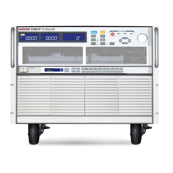
- Page 1 33501 Series High power Electronic Load Operation manual S/N:90033503 REV:G...
- Page 2 会也可能不会含有所有所列的部件。This table shows where these substances may be found in the supply chain of Prodigit electronic information products, as of the date of sale of the enclosed product. Note that some of the component types listed above may or may not be a part of the enclosed product. ○:表示该有毒有害物质在该部...
- Page 3 SAFETY SYMBOLS Direct current (DC) Alternating current (AC) Both direct and alternating Three-phase alternating current Protective earth (ground) On (Supply) Off (Supply) Fuse Caution!Refer to this manual before using the meter. Caution, risk of electric shock CAT IV – Is for measurements performed at the source of the low-voltage installation. CAT III –...
- Page 4 Approved by: Vincent Tan Acts Certification and Testing Services 2008/5/6 Document holder: Prodigit Electronics Co., Ltd. Type of product: DC Electronic Loads Type designation: 33501, 33511, 33521, 33531, 33541, 33512,33513,33514,33515,33532,33533 Technical data: 115/230 Vac, 50 / 60 Hz, 300 W,...
-
Page 5: Table Of Contents
33501 Series High Power Electronic load operation manual Table of Contents CHAPTER 1 INTRODUCTION ......................1-1 1-1. G .......................1-1 ENERAL DESCRIPTION 1-2. F ..........................1-9 EATURES 1-3. A ..........................1-9 CCESSORIES 1-4. O ............................1-9 PTION 1-5. S .........................1-9 PECIFICATIONS CHAPTER 2 INSTALLATION ......................2-1 2-1. - Page 6 Fig 1-5 Constant Power mode ....................1-7 Fig 1-6 Dynamic Wave form....................1-7 Fig 1-7 Rise Time Transition Limitation ................1-8 Fig 1-8 Block Diagram of 33501 Series Electronic Load..........1-13 Fig 2-1 SET OF SWITCH ......................2-1 Fig 2-2 AC LINE RECEPTACLE ..................2-1 Fig 2-3 33501 FRONT/REAR PANEL ..................2-3 Fig 2-4 33501 Series High Power Load Rear panel............2-4...
- Page 7 Tables Table 1-1 AC INPUT Specifications..................1-9 Table 3-1 33501 initialize....................3-12 Table 3-2 33511 initialize....................3-12 Table 3-3 33521 initialize....................3-13 Table 3-4 33531 initialize....................3-13 Table 3-5 33541 initialize....................3-14 Table 3-6 33512 initialize....................3-14 Table 3-7 33513 initialize....................3-15 Table 3-8 33514 initialize....................3-15 Table 3-9 33515 initialize....................3-16 Table 3-10 33532 initialize....................3-16 Table 3-11 33533 initialize....................3-16 Table 3-12 the resolution of range I/II vs.
-
Page 8: Chapter 1 Introduction
Chapter 1 Introduction 1-1. General description The 33501 Series Electronic Load is designed to test, evaluation and burn-in of DC power supplies and batteries. The 335011 Series electronic load can be operated for manual and GPIB operation. The power contour of 33501 1800 Watts Electronic Load is shown in Fig 1- 1.1~1-1.5, it has an input from 0-360A, and 0 -60V current and voltage operating range... -
Page 9: Fig 1-1.3 33521 0-60V / 0-480A 2400W Power Contour
1-2 PRODIGIT Voltage 2400W CONTOUR 0.35 0.175 Current 40 68.57 120 480 A Fig 1-1.3 33521 0-60V / 0-480A 2400W Power Contour Voltage 3600W CONTOUR 0.45 Current 480 A 60 80 90 Fig 1-1.4 33531 0-60V / 0-480A 3600W Power Contour... -
Page 10: Fig 1-1.6 33512 0-60V / 0-360A 5400W Power Contour
33501 Series Operation Manual 1- Voltage 5400W CONTOUR Current 360 A Fig 1-1.6 33512 0-60V / 0-360A 5400W Power Contour Voltage 7200W CONTOUR Current 480 A 120 180 Fig 1-1.7 33513 0-60V / 0-480A 7200W Power Contour... -
Page 11: Fig 1-1.8 33514 0-60V / 0-600A 9000W Power Contour
1-4 PRODIGIT Voltage 9000W CONTOUR Current 600 A 150 225 Fig 1-1.8 33514 0-60V / 0-600A 9000W Power Contour Voltage 10800W CONTOUR Current 180 270 720 A Fig 1-1.9 33515 0-60V / 0-720A 10800W Power Contour... -
Page 12: Fig 1-1.10 33532 0-60V / 0-720A 5400W Power Contour
Fig 1-1.11 33533 0-60V / 0-960A 7200W Power Contour CC Mode: With the operating mode of constant current, the 33501 Series Electronic load will sink a current in accordance with the programmed value regardless of the input voltage (see Fig.1-... - Page 13 INPUT VOLTAGE Fig 1-2 Constant Current mode CR Mode: At constant resistance mode, The 33501 Series Electronic Load will sink a current linearly proportional to the load input voltage in accordance with the programmed resistance setting (see Fig 1-3). LOAD...
-
Page 14: Fig 1-5 Constant Power Mode
33501 Series Operation Manual 1- CP Mode: At Constant Power mode, the 33501 Series Electronic Load will attempt to sink load power (load voltage x load current) in accordance with the programmed power. (See Fig 1-5). P O W E R... -
Page 15: Fig 1-7 Rise Time Transition Limitation
1-8 PRODIGIT Slew Rate: Slew rate is defined as the change in current or voltage over time. A programmable slew rate allows a controlled transition from one load setting to another to minimize induced voltage drops on inductive power wiring, or to control induced transients on a test device (such as would occur during power supply transient response testing). -
Page 16: Features
33501 Series Operation Manual 1- 1-2. Features 1-2-1 CC, CR, CV, CP, Dynamic, and Short Operating Mode. 1-2-2 Fully GPIB control of Load condition setting and meter read back. 1-2-3 Dual high accuracy & resolution 4 1/2 digit voltage and current meter. - Page 17 1-10 PRODIGIT Model 33501 33511 33521 33531 33541 INPUT RATINGS Power (Watt) 2400 W 3600W 2400W 3600W 3600 W Current (Ampere) 240 A 240 A 480 A 480 A 720A Voltage (Volt) 60 V 60 V 60 V 60 V...
- Page 18 33501 Series Operation Manual 1- Model 33512 33513 33514 33515 33532 INPUT RATINGS Power (Watt) 5400 W 7200W 9000W 10800W 5400 W Current (Ampere) 360 A 480 A 600 A 720 A 720A Voltage (Volt) 60 V 60 V 60 V...
- Page 19 1-12 PRODIGIT Model 33533 INPUT RATINGS Power(Watt) 7200 W Current(Ampere) 960 A Voltage(Volt) 60 V PROTECTIONS Over Power Protection(OPP) ≒ 7560W Over Current Protection(OCP) ≒ 1008A Over Voltage Protection(OVP) ≒ 63V Over Temp. Protection(OTP) ≒ 85℃ RANGE 0~96/960 A CC MODE RESOLUTION 25.6mA/256mA...
-
Page 20: Fig 1-8 Block Diagram Of 33501 Series Electronic Load
33501 Series Operation Manual 1- 1-6. Block diagram The functional block diagram of 33501 Series Electronic Load is illustrated in Fig 1-8. Fig 1-8 Block Diagram of 33501 Series Electronic Load... - Page 21 1-14 PRODIGIT The load current level and load status are received from front panel of 33501, the two 12 bit D/A converter receive digital data of load current and transfer as an analog signal, the load current slew rate is controlled by the two 8 bit D/A converters, the Thigh and Tlow duration is set by two 16 bit trimmer, these six parameters constitute the wide range pulse generator, and can be used to test the power supply.
-
Page 22: Chapter 2 Installation
Prodigit's sales and service office or representative. Your 33501 Series high power load was shipped with a power cord for the type of outlet used at your location. If the appropriated cord was not included, please contact your nearest Prodigit sales office to obtain the correct cord. -
Page 23: Grounding Requirements
2-4. Adjust the feet The 33501 Series high power load is equipped with feet and tilt stands installed and is ready for used as a bench instrument. The feet provide a good viewing angle for bench-top use. -
Page 24: Gpib Connection
33501 Series Operation Manual 2-3 2-8. GPIB connection The GPIB connector on the rear panel connects the 33501 Series high power load to the controller and to other GPIB devices. An GPIB system can be connected in any configuration (star, linear, or both) as long as 2-8-1 The maximum number of devices including the controller is no more than 15. -
Page 25: Rs-232C Connection
Fig 2-4 33501 Series High Power Load Rear panel 2-10.Remote control Port The D-sub 9 pin connector on the rear panel connects the 33501 Series high power load to the PRODIGIT mode 9931C remote controller and to replace the RECALL option key 1 to 5 on the front panel of 33501 Series high power load. -
Page 26: Analog Programming Bnc Input
33501 Series Operation Manual 2-5 2-11 Analog programming BNC input The BNC connector on the rear panel connects . The 0 to 10V Analog signal can program the 0 to full scale input range in the CC mode ( 0 to 24A range when load current setting is less than 24A, or 0 to 240A range when load current setting is higher than 24A) or in the CP mode (0 to 2400W). - Page 27 After press the STORE key, it is available and useful to operate the front panel key on the 33501 series Electronic load . However, the STATE LED will be OFF if any key on any load module is operated, this indicates the front panel state of load module is not the same as STORE state.
-
Page 28: Auto Sequence Testing Function Description
Each test step has t1 (test time) and t2 (delay time), the unit is 100mS, the range is 0.1S - 9.9S in 100mS resolution. 33501 series mainframe will check each module GO/NG at the end of t1 (test time), the next step will be started after duration t2 (delay time). -
Page 29: Fig 2-9 Store (Edit) Mode Operationo Flow-Chart
(flash) if there is at least one failure during the test. 2-14-2-4 User can press Start key to continue another test, or the 33501 series can quit from Auto-Sequence mode by press EXIT key. -
Page 30: Fig 2-10 Test Mode Operation Flow-Cha
33501 Series Operation Manual 2-9 1.Press S3+S4 key, and S3 and S4 LED are ON S3+S4 Show n1-n9 Initial = n1 2.Show AUTO SEQ. No.1-No.9, Press Up/Down key to set n1-n9 3.Press Start key to Start Mode Start Mode Press Start key 1.To recall correspond memory which had been stored in n1-n9 memory... -
Page 31: Load Current Slew Rate Setting
The slew rate determines a rate at which the current changes to a new programmed value. The slew rate can be set at the front panel or via GPIB on the rear panel of 33501 Series high power load. -
Page 32: Chapter 3 Operation
33501 Series Operation Manual 3-1 Chapter 3 Operation This chapter describes the front panel function and operation of each 33501 Series load, the memory Store/Recall, GPIB and RS-232 remote programming are described in the mainframe operation manual. Please refer to the mainframe's operation manual for mainframe store/recall and GPIB/RS-232C programming. -
Page 33: Fig 3-2 33501 Series High Power Electronic Load
CC, CR, CV, CP mode LED will be lit respectively when the appropriate operating mode is selected. There are two programming ranges in Constant Current and Constant resistance mode respectively; the 33501 series can adjust to the best fit range automatically according to the programmed load level. The rule is described below: 3.1.3.1... - Page 34 When the auto-sense of V-sense function is programmed, the auto-sense circuit of 33501 series electronic load can check the V-sense cable is connected or not, the V- sense BNC input is detected if it is greater than 0.5V (33501, 33511) or 2.5V (33521) or not, if yes then the 5 digit DVM measures the sense BNC input, otherwise, the 5 digit DVM measures the DC input terminals of the load module.
- Page 35 MODE and CC, CR, CV, CP Indicator There are four operating modes can be selected by press the " MODE " key on the 33501 series Electronic Load module. The sequence is Constant Current ( CC ), Constant Resistance ( CR ), Constant Voltage ( CV ), Constant Power ( CP ) and then repeat while press the"...
- Page 36 LOAD OFF status. The LOAD will return to the previously programmed values when the LOAD key is turned to ON again. The Load ON LED indicates the 33501 series electronic load is ready to sink current from DC input.
- Page 37 LED can be indicated the High or Low level in the Static mode. The only fact is switching the 33501 series load module from Dynamic load to Static load; it can determine the load current is High or Low load current level.
- Page 38 33501 Series Operation Manual 3-7 3.1.15 DYN setting key and LED DYN setting key is setting Dynamic Mode parameter, There are rise, fall, Thigh and Tlow parameters, Setting the parameter is rotating the knob switch. Press any key to escape the DYN parameters setting mode.
- Page 39 3-8 PRODIGIT knob. Note. The V-Hi and V-Lo parameter is difference with the V-Hi and V-Lo in the LIMITfunction. 3.1.17.6 START/STOP Test key. Press START/STOP key to start or stop the short test by SHORT test setting parameter when SHORT test function is enabled.
- Page 40 33501 Series Operation Manual 3-9 setting range is 0.00W to the full scale of the CP mode specification. The setting is by rotating the setting knob. 3.1.18.6 Vth : Setting threshold voltage; The LCD display shows “OPP”, “Vth” and 0.50VI(initial) from upper to lower 5 digits LCD display, the setting range is 0.00V to the full scale of the Voltage specification.
- Page 41 Please take care of the voltage and current rating not to excess the maximum rating of each 33501 series load module. Please check the polarity of DC input connection also before testing.
-
Page 42: Fig 3-3 Remote Sense Connection On Front Panel(When Current ≦60A)
33501 Series Operation Manual 3-11 Fig 3-3 Remote sense connection on front panel(when current ≦60A) Fig 3-4 Remote sense connection on rear panel(When current >60A) 3.1.24 I-monitor The I-monitor analog signal is proportional to the load current flow through the electronic load module. -
Page 43: Table 3-1 33501 Initialize
3-12 PRODIGIT 3-2. Initial setting of 33501 series load module When you receive the 33501 series electronic load, the load value initial setting after power ON is listed in table 3-1~3-5 respectively, this is the factory or initial setting. 項 目... -
Page 44: Table 3-3 33521 Initialize
33501 Series Operation Manual 3-13 項 目 起始值 項 目 起始值 CC L 0.0000 A 60.00 V CC H 0.0000 A 0.000 V CR H 468.7 Ω 480.00 A CR L 468.7 Ω 0.000 A CV H 60.00 V 2400.0 W CV L 60.00 V... -
Page 45: Table 3-5 33541 Initialize
3-14 PRODIGIT 項 目 起始值 項 目 起始值 CC L 0.0000 A 60.00 V CC H 0.0000 A 0.000 V CR H 312.4 Ω 720.00 A CR L 312.4 Ω 0.000 A CV H 60.00 V 3600.0 W CV L 60.00 V... -
Page 46: Table 3-7 33513 Initialize
33501 Series Operation Manual 3-15 項 目 起始值 項 目 起始值 CC L 0.0000 A 60.00 V CC H 0.0000 A 0.000 V CR H 468.7 Ω 480.00 A CR L 468.7 Ω 0.000 A CV H 60.00 V 7200.0 W CV L 60.00 V... -
Page 47: Table 3-9 33515 Initialize
3-16 PRODIGIT 項 目 起始值 項 目 起始值 CC L 0.0000 A 60.00 V CC H 0.0000 A 0.000 V CR H 312.3 Ω 720.00 A CR L 312.3 Ω 0.000 A CV H 60.00 V 10800.0 W CV L 60.00 V... -
Page 48: Input Terminal And Wire Consideration
33501 Series Operation Manual 3-17 項 目 起始值 項 目 起始值 CC L 0.000 A 60.00 V CC H 0.000 A 0.000 V CR H 234.3 Ω 960.0 A CR L 234.3 Ω 0.000 A CV H 60.00 V 7200.0 W CV L 60.00 V... -
Page 49: Load Current Course/Fine Increase/Decrease Adjustment Knob
3-18 PRODIGIT to limit the voltage drop to less than 0.5V per lead. 3-4. Load current course/fine increase/decrease adjustment knob Change amount that CC/CR/CV/CP MODE( CR contrary ) load current adjusts form Table 3- 7 shows analyzes one degree of relations with knobing. Push the knob when operate (the... - Page 50 33501 Series Operation Manual 3-19 RANGE I RANGE II 33521 FULL SCALE LOAD 480 A CURRENT CURRENT RANGE 480.0 A METER RESOLUTION 0.1 A COURSE/FINE LOAD CURRENT ADJUSTMENT Knob CC Mode 1.28A 128mA 12.8mA 12.8A 1.28A 128 mA 3.3mΩ 0.33mΩ...
- Page 51 3-20 PRODIGIT RANGE I RANGE II 33512 FULL SCALE LOAD 360 A CURRENT CURRENT RANGE 360.0 A METER RESOLUTION 0.1 A COURSE/FINE LOAD CURRENT ADJUSTMENT KEY CC Mode 960mA 96mA 9.6mA 9.6A 960mA 96mA CR Mode 106.66ms 10.666ms 1.066ms 6.7mΩ...
-
Page 52: Table 3-12 The Resolution Of Range I/Ii Vs. Course/Fine Load Setting Key
33501 Series Operation Manual 3-21 RANGE I RANGE II 33515 FULL SCALE LOAD 720 A CURRENT CURRENT RANGE 720.0 A METER RESOLUTION 0.1 A COURSE/FINE LOAD CURRENT ADJUSTMENT KEY CC Mode 1.92A 192mA 19.2mA 19.2A 1.92A 192mA CR Mode 320ms 32ms 3.2ms... -
Page 53: I-Monitor
3-22 PRODIGIT 3-5. I-monitor The I-monitor BNC is designed to monitor the Electronic load's input current or short current, An isolated amplifier output 0V to 10V full scale signal indicates the zero to full scale current for each Electronic load module. -
Page 54: Protection Features
When the Over power condition is occurred, the Digital Current Meter's LCD display will indicate " OPP ". As soon as the temperature of 33501 Series heat sink greater than 85 degree, the Over temperature protection is occurred, the Digital Current Meter's LCD display will indicate " OtP "... -
Page 55: Chapter 4 Gpib/Rs-232 Programming Operation
Chapter 4 GPIB/RS-232 programming operation 4-1. Introduction The rear panel GPIB/RS-232 interface of 33501 Series electronic load is designed to connect PC (Personal Computer) or NOTEBOOK PC with GPIB interface, the NOTEBOOK PC acts as a remote controller of 33501 Electronic Load. -
Page 56: Gpib/Rs-232 Command List
4-2 PRODIGIT 4-3. GPIB/RS-232 COMMAND LIST SETTING COMMAND Function Command Format SET VOLTAGE VOLT:{LOW|HIGH}{SP}{NR2}{;|NL} SET PERD PERD:{LOW|HIGH}{SP}{NR2}{;|NL} RISE{SP}{NR2}{;|NL} SET RISE SLEW-RATE FALL{SP}{NR2}{;|NL} SET FALL SLEW-RATE SET SHORT ON/OFF SHOR{SP}{0|1|OFF|ON}{;|NL} DYN{SP}{0|1|LOW|HIGH}{;|NL} SET DYNAMIC ON/OFF CURR:{LOW|HIGH}{SP}{NR2}{;|NL} NR2:###.#### SET CURRENT SET RESISTANCE RES:{LOW|HIGH}{SP}{NR2}{;|NL} SET LOAD ON/OFF LOAD{SP}{0|1|OFF|ON}{;|NL}... -
Page 57: Table 4-2 Gpib/Rs-232 Query Command Summary
33501 Series Operation Manual 4-3 QUERY COMMAND Function Command Syntax ECHO VOLT:{LOW|HIGH}?{;|NL} QUERY VOLTAGE ±###.#### QUERY PERIOD PERD:{LOW|HIGH}?{;|NL} ####.#### RISE?{;|NL} QUERY RISE SLEW-RATE #.#### FALL?{;|NL} QUERY FALL SLEW-RATE #.#### QUERY SHORT ON/OFF SHOR?{;|NL} 1:ON, 0:OFF QUERY DYNAMIC ON/OFF DYN?{;|NL} 1:ON, 0:OFF CURR:{LOW|HIGH}?{;|NL}... -
Page 58: The Description Of Abbreviation
4-4 PRODIGIT 4-4. The description of abbreviation 1. SP:Space, the ASCII code is 20 Hexadecimal. 2. ; :Semicolon, Program line terminator, the ASCII code is OA Hexadecimal. 3. NL:New line, Program line terminator, the ASCII code is OA Hexadecimal. 4. N :Integer number from 1 to 8. -
Page 59: Gpib Command Description
LOW level is 10 times of resolution at each range, the 33501 Series Electronic Load will adjust and limit of the programmed values. If the programmed HIGH level is equal or less than LOW level, the 33501 Series load will adjust and limit HIGH level to be higher 10 times programming resolution of LOW level, and vice versa at the programmed LOW level is equal or more than HIGH level. - Page 60 4-6 PRODIGIT 4. Please make sure range I/II command before execute the load current setting command, otherwise the 33501 Series load current after programming the RANGE command. 5. LOW|HIGH option is for 33501 series electronic load module. 6. The engineering unit for load resistance is Ohms.
- Page 61 33501 Series Operation Manual 4-7 STORE Purpose:STORE the load level and load status into the non-volatile memory. Command syntax:STORE {SP} {1|2|3|4|5} {NL} Description: 5 different states with load status and load current into the non-volatile memory. Note: The new load level and load status can overcome the load level and status if STORE new state number, because the memory location is the same for same STORE state number.
- Page 62 HIGH and LOW level is 10 times of resolution, the 33501 Series Electronic Load will adjust and limit of the programmed values. If the programmed HIGH level is equal or less than LOW level, the 33501 Series load will adjust and limit HIGH level to be higher 10 times programming resolution of LOW level, and vice versa at the programmed LOW level is equal or more than HIGH level.
- Page 63 The effective RISE load current slew rate can be programmed is the sixth digit after the decimal point. If the programming loads current level over the maximum specification at programmed range of 33501 Series electronic load, the fastest RISE slew rate will be sent to the load module.
- Page 64 This command applies the short across the input of the electronic load. The maximum short resistance is 0.004, 0.002 and 0.0014 ohms for 33501 Series, Executing SHOR does not effect any programmed settings and the electronic load will return to them when the short is removed.
- Page 65 Purpose: The load power setting in Constant Power mode. Command Syntax: CP :{ HIGH|LOW} {SP} {NR2} {; |NL} Description: This command is used to set the load Power level of 33501 series electronic load. VOLTAGE Limit Purpose:To set the upper/lower limit value of threshold voltage.
- Page 66 4-12 PRODIGIT POWER Limit Purpose:To set the upper/lower limit value of threshold power (W). Command syntax:LIM: POW :{ HIGH|LOW} {SP} {NR2} {; |NL} Description: This command is to set the upper/lower limit value of threshold power (WATT). When power (WATT) is lower than this lower limit value or higher than the upper limit value, NG indicating light will come on to indicate〝NO GOOD〞.
- Page 67 33501 Series Operation Manual 4-13 2.Query Command CURR Purpose:The Constant Current mode's LOW or HIGH load current level query command. Command syntax:CURR:{LOW|HIGH}?{NL} Description: CURR: LOW? ; return the presently programmed low load current level in Constant Current mode. CURR: HIGH? ; return the presently programmed high load current level in Constant Current mode.
-
Page 68: Table 4-4 Prot Status Byte Register
Table 4-4 describes the status byte the happened on the 33501 Series electronic load. The PROT status byte register is cleared when a CLER command clear all of the PROT and ERR status registers. - Page 69 33501 Series Operation Manual 4-15 MEAS : VLOT Purpose:The reading of 4 1/2 digit voltage meter read back query command. Command syntax:MEAS:VOLT? {NL} Description: MEAS: VOLT? ; return the presently 4 1/2 digital voltage meter reading. The returned data format is shown in Table 4-2, the engineering unit is〝V〞.
- Page 70 4-16 PRODIGIT FALL Purpose:The dynamic load mode's FALL slew rate query command. Command syntax:FALL?{NL} Description: FALL? return the presently programmed low load current level in Constant Current mode. The returned data format is shown in Table 4-2, the engineering unit is〝A/us〞.
- Page 71 33501 Series Operation Manual 4-17 SENSE ON/OFF Purpose:To read the setting condition of Sense ON or OFF. Command syntax:SENS?{;|NL} Description: SENS? Read back the setting condition of SENS.〝0〞denotes OFF,〝1〞denotes ON. VOLTAGE Limit Purpose:To read the set value of upper/lower limit value of threshold voltage.
-
Page 72: Chapter 5 Applications
Local sensing is used in application where lead lengths are relatively short, or where load regulation is not critical. The 4 1/2 digit voltage Meter of 33501 Series Electronic load measures the voltage of DC INPUT Terminal automatically; load leads should be bundled or tie-wrapped together to minimize inductance. -
Page 73: Remote Sense Connections
Remote sensing compensates for the voltage drop in applications that require long lead lengths. The 4 1/2 digit voltage Meter of 33501 Series electronic load measures the voltage of Vsense BNC input Terminal automatically, so the high accuracy 4 1/2 digit voltage Meter can measure the specific points voltage of the power supply's output voltage. -
Page 74: Constant Current Mode Application
33501 Series Operation Manual 5-3 5-3. Constant Current mode application The Constant Current mode is very suitable to test the LOAD REGULATION, CROSS REGULATION, OUTPUT VOLTAGE and DYNAMIC REGULATION of the power supply testing, and test the DISCHARGE CHARACTERISTIC, LIFE CYCLE of the battery testing. -
Page 75: Fig 5-4 Dynamic Load Current With Independent Programmed Rise/Fall Slew Rate
5-4 PRODIGIT 2. Dynamic mode: I. Built-in Pulse generator: (Fig 5-4) Major application: a. Power supply load transient response testing b. Power recovery time testing c. Pulse load simulation d. Power component testing Description: The maximum Rise/Fall current slew rate or minimum Rise/fall time is the time required for the load input to change from 10% to 90% or from 90% to 10% of the programmed High to Low load level. -
Page 76: Constant Voltage Mode Application
33501 Series Operation Manual 5-5 5-4. Constant Voltage mode application Major application: a. Current source testing. b. Power supply current limit characteristic testing CURRENT SOURCE INPUT LOAD ELECTRONIC CV MODE CONSTANT VOLTAGE SETTING CV SETTING INPUT VOLTAGE LOAD CURRENT POWER SUPPLY CURRENT... -
Page 77: Constant Resistance Mode Application
5-6 PRODIGIT 5-5. Constant Resistance mode application Major application: a. Voltage source or Current source testing b. Power resister simulation. CURRENT SOURCE VOLTAGE SOURCE ELECTRONIC LOLAD ELECTRONIC LOLAD CR MODE CR MODE INPUT VOLTAGE LOAD RESISTANCE SETTING OUTPUT LOAD CURRENT... -
Page 78: Constant Current Source Operation
33501 Series Operation Manual 5-7 5-6. Constant current source operation The Electronic load can also be used as a high current constant current source if the following connection is made. This function can be used as a battery charger or other application.
Need help?
Do you have a question about the 33501 Series and is the answer not in the manual?
Questions and answers
Can we test Average DC load and peak load simultaneously, if yes give the options and suggest how to perform the test