Table of Contents
Advertisement
Quick Links
Advertisement
Table of Contents

Subscribe to Our Youtube Channel
Related Manuals for ABB MNS-Up


Summary of Contents for ABB MNS-Up
- Page 1 — D I S T R I B U T I O N S O LU T I O N S MNS-Up Service Manual • Capex and footprint reduction • Reduced installation time as all the system is pre-tested • Flexibility and scalability with full plug-in UPS modules •...
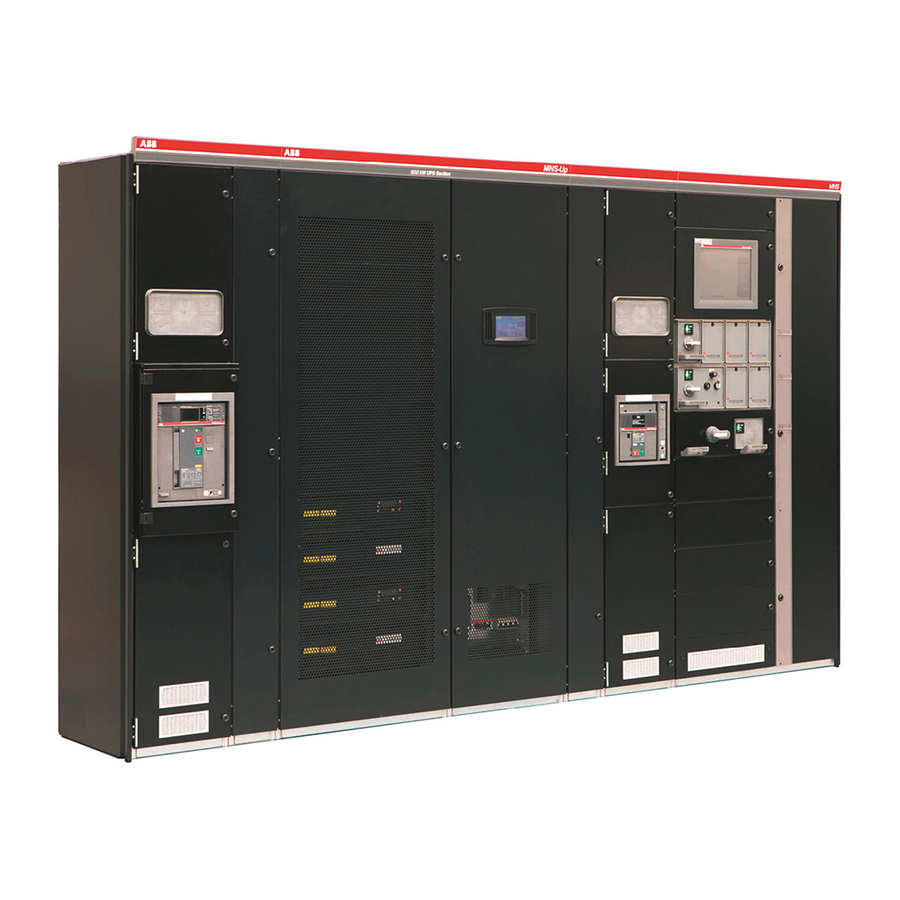
- Page 2 The MNS-Up system is an integrated low-voltage switchgear system comprised of incoming and central manual bypass feeders, MNS-Up UPS sections and MNS 3.0 outgoing sections. The system is based on the well- known MNS system, in which the MNS-Up UPS is integrated.
-
Page 3: Table Of Contents
09. MNS-Up Module installation 10. Handling of EMC boards 11. Communication boards 12. MNS 3.0 sections 13. Commissioning 14. Operating of MNS-Up system 15. Tightening torques for screw connection 16. Spare parts 17. Onsite inspection and maintenance 18. Maintenance intervals... - Page 4 2.9.1 Capacitors 2.9.2 CT’s 2.9.3 Auxiliary or temporary supply General technical data General technical data MNS-Up UPS General characteristics System description MNS-Up UPS section Packing, storage and transportation General Recommended packing methods 5.2.1 The packing for normal road transport 5.2.2 The seaworthy packing 5.2.3...
- Page 5 TA B L E O F C O N T E N T S Clearance above MNS-Up system Clearance behind MNS-Up system, clearance in front of the section Frame and enclosure 7.4.1 EMC measures for enclosure 7.4.1.1 EMC seals between sections 7.4.1.2...
-
Page 6: Introduction
— Introduction... - Page 7 I N T R O D U C T I O N — Introduction This manual id dedicated to the MNS-Up section hosting the UPS modules; for the other cubicles and the UPS modules please refer to dedicated Manuals: • MNS Installation and maintenance manual 1TGC902040B0201 •...
- Page 8 — Safety first...
-
Page 9: Safety Requirements
S A F E T Y F I R S T — Safety first Safety requirements when working on electrical systems Safety relevance This Service Manual contains further safety relevant aspects in the document. This is highlighted with the following symbol: When working on specific tasks or areas in the switchgear it is mandatory to follow the safety requirements and advises outlined in this document. -
Page 10: Warning Signs And Labels
If in doubt of the task to be carried out, ABB Service technicians should be utilized for the work. Never utilize untrained personnel who are not certified with the system. -
Page 11: Five Safety Rules
S A F E T Y F I R S T Five safety rules The DEAD circuit condition must be established prior to commencement of work and must be ensured at the place of work for the duration of work in compliance with the five safety rules (EN50110-1 2013 chapter 6.2): 1. -
Page 12: General Technical Data
— General technical data... -
Page 13: General Technical Data
IPH, Institut für Prüffeld- und Hochspannungstechnik, Berlin / Germany Test certificates High Power Laboratory, ABB AG, Ratingen / Germany Technology center laboratory, ABB s.r.o, Brno / Czech Republic Rated insulation voltage U 1 000 V 3~, 1 500 V- Rated operating voltage U... -
Page 14: Mns-Up Ups General Characteristics
Apparent active power per section Power, range 100 - 3000 UPS type: on-line, transformer-free, modular, decentralized parallel architecture Parallel capability: up to 6 MNS-Up sections Battery: not included Performance classification: VFI-SS-111 Mechanical Dimensions (width × height × depth) 1400 x 2200 x 1400 or 1400 x 2200 x 1600 Mass, approx. - Page 15 G E N E R A L T E C H N I C A L D ATA General characteristics of active and passive module Model: Conceptpower DPA500 Values Unit Active submodule Passive submodule Power ratings: apparent active UPS type: on-line, transformer free, modular, decentralized parallel architecture Parallel capability: up to 6 frames For higher ambient temperatures, there is a restriction in the operating time in battery mode.
-
Page 16: System Description
— System description... -
Page 17: System Description
3 Input and output neutral conductor 12 Partition wall 3 to main busbar area 4 PE main busbar 13 EMC filter board input line 5 Active MNS-Up UPS module 14 EMC filter board output line 6 Passive MNS-Up UPS module 15 Multifunction wall... -
Page 18: Packing
— Packing, storage and transportation... -
Page 19: General
General overview of standard module solutions (customer specific solutions not mentioned) If no special instructions are given by the customer, packing is carried out based on ABB shipping guidelines and a suitable method of shipping is selected. Approximate weights for calculation are listed in below tables. - Page 20 Approximate weights per 3 and 4 pole ACB sections (incomming feeders and couplers) Approximate weight of MNS-Up section Section type Approximate weight [kg] MNS-Up empty section (without UPS modules) Table 5-03 Approximate weights of MNS-Up section Approximate weight of UPS modules...
- Page 21 Module size and weight highly depends on customer requirements and specification. Above mentioned values are only informative should detailed clarification be required please contact your local ABB representative. For easy and safe operation, withdrawable modules above or equal 12E are equipped with additional side handles.
-
Page 22: Recommended Packing Methods
M N S - U P S E R V I C E M A N U A L Recommended packing methods The sections are protected by suitable packaging during transport and possible intermediate storage. 5.2.1 The packing for normal road transport Transport frame consisting of: •... -
Page 23: The Seaworthy Packing
PA C K I N G , S TO R A G E A N D T R A N S P O R TAT I O N 5.2.2 The seaworthy packing The export/seaworthy packaging (for sea transport and truck or train transport outside continental Europe) comprises: 1. - Page 24 M N S - U P S E R V I C E M A N U A L Do not incline Fragile Gravity center CZ − 003 Marking for ropes Do not stack HT IPPC Figure 5-05 Transport marking All sawn wood shall be thermal treated according ISPM 15 standard.
- Page 25 PA C K I N G , S TO R A G E A N D T R A N S P O R TAT I O N 3. Overhanging parts and sharp edges are covered by miralon to protect additional packing. Figure 5-06 Seaworthy packing procedure, steps 1, 2 &...
- Page 26 M N S - U P S E R V I C E M A N U A L 5. Miralon 2 mm is placed all over the shipping section and is stripped by tape. The tape is supported by plastic edge protection.
- Page 27 PA C K I N G , S TO R A G E A N D T R A N S P O R TAT I O N 7. Wooden box assembly and execution of aperture for humidity detector verification. 8.
- Page 28 M N S - U P S E R V I C E M A N U A L 9. Location of crash and turnover protection (shockwatch label and tilt watch) 10. PE foil UV resistant shall be utilised on the top of the packing Figure 5-09 Seaworthy packing procedure, steps 9 &...
-
Page 29: Horizontal Transportation
PA C K I N G , S TO R A G E A N D T R A N S P O R TAT I O N 5.2.3 Horizontal transportation In situations where that the structural conditions on site, e.g. height of door frame < 2200 mm, does enable the MNS sections to enter the e-room in standing (vertical) position, all individual sections may be transported horizontally. -
Page 30: Packaging Of Switchgear Components
(module location, type, order number). The fuses remain in the modules. Information concerning the procurement of standard boxes can be obtained from the ABB shipping department. The quality of the internal packaging depends on the type of goods to be packaged and shall be selected by the ABB ship- ping department. -
Page 31: Mns-Up Filter Modules
5.3.4 MNS-Up Filter modules MNS-Up filter modules must be removed from the MNS-Up section and packed in the original boxes before shipping. Unloading and transport at site The loads must be lowered onto a flat surface by either a crane or fork lift truck. -
Page 32: Transport By Crane
M N S - U P S E R V I C E M A N U A L Sections may easily tip over when transported with a hand-pulled truck. Therefore the distance between the wooden cross beam or the pallet and the ground should not be more than 3 mm (see Figure 3-15). max. - Page 33 PA C K I N G , S TO R A G E A N D T R A N S P O R TAT I O N 1600 kg at a rope 2400 kg at a rope angle of 120° max. angle of 120°...
-
Page 34: Transport By Truck
M N S - U P S E R V I C E M A N U A L 5.4.3 Transport by truck The loading of the sections can be undertaken with a fork lift from the side of the truck. In case of collocate sections an additional spacer between the sections is necessary (see Figure 3-18). -
Page 35: Storage Of Spare Modules
PA C K I N G , S TO R A G E A N D T R A N S P O R TAT I O N 5.5.1 Storage of spare modules • Storage is only allowed in dry rooms. •... -
Page 36: Transport
— Transport... -
Page 37: Mns-Up Section
MNS-Up section • The MNS-Up sections must be shipped as individual sections, due to their dimensions and weight. • ACB sections and MNS 3.0 sections may be shipped in sections of max 3 m in length or 3 sections. Shipping sections shall only be transported in upright position •... -
Page 38: Crane Transport
M N S - U P S E R V I C E M A N U A L 6.1.3 Crane transport For transport by crane, the shipping units are equipped with lifting angles. Fastening of any lifting device directly to the frame sections is not permitted. The lifting rope angle at the crane hook must not be larger than 120°. -
Page 39: Mns-Up Modules
Figure 6-05 Frame corner joint with lifting angle MNS-Up Modules The MNS-Up active and passive modules must be shipped in their original packing. Stacking of boxes is allowed, up to two boxes. Circuit breakers Circuit breaker must be treated in the following way: Fixed circuit breaker must be additionally braced. -
Page 40: Erecting
— Erecting... -
Page 41: Before Installation
The holes in the gland plates need to be prepared on site, based on the number and cross section of the cables used. Figure 7-01 Floor cut-outs for MNS-Up ups section Floor cut-outs for other MNS 3.0 sections shall be done as described in the MNS Service Manual. -
Page 42: Clearance Above Mns-Up System
Clearance above MNS-Up system The MNS-Up system uses forced ventilation to keep the UPS module temperature constant. The air inlet to the UPS section is from the front, the air outlet is on the top. Therefore, there must be a clear-ance of at least 100 cm above the MNS-Up UPS section. -
Page 43: Frame And Enclosure
7.4.1.3 EMC seals for bottom plate All MNS-Up sections require bottom plates due to EMC requirements. The bottom plates need to be fixed in a distance of 225 mm, and no additional EMC seals are required. 7.4.2... -
Page 44: Main Busbars
The connecting material to join the main busbar and PE busbars is part of the assessor pack delivered with each shipping section. Access to the shipping split is granted in the filter section of the MNS-Up section. To get access to the shipping split, all filter modules and partition wall 3 need to be removed. - Page 45 After joining the main busbars, the partition wall must be reinstalled and correctly fixed. The PE busbar is located in the front of the MNS-Up sections. The connection at shipping sections must be done according to the MNS service manual.
-
Page 46: Battery Connection
Individual battery connection 7.6.2 Common batteries In case a common battery set must be connected to one MNS-Up section, the battery connection bars of the different mod- ule levels need to be connected using copper links. Figure 7-10 Common battery connection... - Page 47 E R E C T I N G...
-
Page 48: Mns-Up Configuration
— MNS-Up configuration... -
Page 49: Single Mns-Up Ups Section Configuration
— MNS-Up configuration Single MNS-Up UPS section configuration A single section configuration requires one MNS-Up section equipped with 1-5 MNS-Up modules. The modules are feeding energy in parallel to the outgoing bar. Figure 8-01 Single section 1 module - 100kw installed Figure 8-02 Single section 2 modules in parallel –... -
Page 50: Active, Passive And Filter Module Placing
Multi-section configuration Please check DPA500 user manual section 2.6. Active, passive and filter module placing 8.3.1 Module arrangement The MNS-Up module sets must be installed from bottom to top. One module set consists of: · Passive module · Active module ·... -
Page 51: Space Covers
M N S - U P C O N F I G U R AT I O N 8.3.2 Space covers Empty space compartments of active, passive and filter modules must be closed using the respective space covers. Figure 8-04 Space cover active passive module combination Figure 8-05 Space cover active passive module combination 1TGB100370r0101... -
Page 52: Mns-Up Module Installation
— MNS-Up Module installation... -
Page 53: Lifting Of Modules
M N S - U P M O D U L E I N S TA L L AT I O N — MNS-Up Module installation Lifting of modules Wheelchair lifts are recommended for lifting modules up or down. Model:... -
Page 54: Adding Of Module Sets
M N S - U P S E R V I C E M A N U A L Adding of module sets MNS-Up modules are always installed as a complete set, since none of the modules can work independently. To install a new module set the following steps are recommended: If possible, switched OFF the complete system and disconnected the loads. - Page 55 M N S - U P M O D U L E I N S TA L L AT I O N...
-
Page 56: Handling Of Emc Boards
— Handling of EMC boards... -
Page 57: Replacing Emc Boards
— Handling of EMC boards In each of the MNS-Up sections, two EMC boards are installed on the distribution bars. The boards are located behind the filter modules. To access the boards, all the filter modules must be removed. A complete system shutdown is required if emc boards must be accessed. - Page 58 M N S - U P S E R V I C E M A N U A L Figure 10-02 EMC board access in MNS-Up filter section Reassemble in the opposite way. Follow the start-up procedure as described in the DPA500 user manual section 6.7.
- Page 59 H A N D L I N G O F E M C B O A R D S...
-
Page 60: Communication Boards
— Communication boards... - Page 61 C O M M U N I C AT I O N B O A R D S — Communication boards The communication boards are located below the control wiring duct in the MNS-Up module. Figure 11-01 Control wiring duct with integrated communication ports Figure 11-02 Communication ports in MNS-Up systems...
-
Page 62: Mns 3.0 Sections
— MNS 3.0 sections... -
Page 63: Handling Of Acbs
Central manual bypass The central manual bypass is used to bypass the UPS system in case maintenance on the MNS-Up UPS modules is required. The central maintenance bypass can be closed even if the MNS-Up UPS modules are switched on. -
Page 64: Commissioning
— Commissioning... -
Page 65: Commissioning
C O M M I S S I O N I N G — Commissioning Follow the two steps for the commissioning. Follow the commissioning procedure as described in the MNS service manual 1TGC902040B0201 section 5. Exception: While performing the insulation test on the main busbar system, the fuses of the EMC boards have to be disconnected. Follow the start-up procedure as described in the DPA 500 user manual section 6.7. -
Page 66: Operating Of Mns-Up System
— Operating of MNS-Up system... -
Page 67: Mns-Up System Operation
— Operating of MNS-Up system 14.1 MNS-Up system operation For operating instructions for the MNS-Up ups system please refere to the conceptpower DPA500 user manual doc no 043275_OPM_ABB_CONCEPTPOWER_DPA_500kW_EN_REV-C. 14.2 Handling/operating ACBs For operating and maintenance on acbs check the respective service manuals supplied with the system. -
Page 68: Tightening Torques For Screw Connection
— Tightening torques for screw connection in MNS-Up... -
Page 69: Seif-Tapping Screws In Plastic Material
T I G H T E N I N G TO R Q U E S F O R S C R E W C O N N E C T I O N I N M N S - U P — Tightening torques for screw connection in MNS-Up 15.1... -
Page 70: Thread Rolling Screws In Metal
M N S - U P S E R V I C E M A N U A L 15.2 Thread rolling screws in metal Hexalobular socket pan Cross recessed pan head Hexagon socket head cap Hexalobular socket Hexagon head screws, head screw, ISO 14583 screws, ISO 7045 screws, ISO 4762... -
Page 71: Screws For Busbar Connections (Cu) And System Connections (Steel/Steel)
T I G H T E N I N G TO R Q U E S F O R S C R E W C O N N E C T I O N I N M N S - U P 15.3 Screws for busbar connections (Cu) and system connections (steel/steel) Hexagon head screws, fully threaded, ISO 4017... -
Page 72: Spare Parts
— Spare parts... -
Page 73: Spare Parts
S PA R E PA R T S — Spare parts Item Description Id-No. Additional information MNS-Up active module (40 °C) 04-3404_SP284 40 °C ambient temperature module MNS-Up active module (35 °C) 04-3404 35 °C ambient temperature module MNS-Up passive module (40 °C) 04-3405_SP284 40 °C ambient temperature module... -
Page 74: Onsite Inspection And Maintenance
— Onsite inspection and maintenance... -
Page 75: Onsite Inspection And Maintenance
O N S I T E I N S P E C T I O N A N D M A I N T E N A N C E — Onsite inspection and maintenance Please refer to MNS Service Manual 1TGC902040B0201 section 7 and maintenance instructions as described in the DPA500 manual section 7.2. -
Page 76: Maintenance Intervals
— Maintenance intervals... -
Page 77: Maintenance Intervals
M A I N T E N A N C E I N T E R VA L S — Maintenance intervals Please refer to MNS Service Manual 1TGC902040B0201 section 7 and DPA500 manual section 7. General visual inspection (repetitive tests): •... -
Page 78: Maintenance Checklist
M N S - U P S E R V I C E M A N U A L 18.1 Maintenance checklist Item no. Work to be performed Measured, test and limit Frequency installation category Remarks values, operating and auxiliary materials General visual inspection (repetitive tests) External inspection... - Page 79 1.3.8 Check measuring loops – In accordance with circuit diagram 1.3.9 Check function of the See Conceptpower DPA500 MNS-Up modules and manual bat-teries Withdrawable technique 2.1.1 Compact modules (6E/4 + 6E/2/8E/4 + 8E/2) – Check easy movement – Remove dust and grease...
- Page 80 M N S - U P S E R V I C E M A N U A L Item no. Work to be performed Measured, test and limit Frequency installation category Remarks values, operating and auxiliary materials Main contact to be checked either according to mentioned time intervals or at latest, after 100 cycles. –...
- Page 81 M A I N T E N A N C E I N T E R VA L S...
- Page 82 Any reproduc- tion, disclosure to third parties or utilization of its contents – in whole or in parts – is forbidden without prior written consent of ABB. © Copyright 2021 ABB. All rights reserved. Specifications subject to change without notice.
- Page 84 — ABB Ltd. Distribution Solutions Electrification business Publication Editor: ABB Schweiz Lenzburg Switzerland Local Contacts on abb.com/mns © Copyright 2021 ABB. All rights reserved. Specifications subject to change without notice.
Need help?
Do you have a question about the MNS-Up and is the answer not in the manual?
Questions and answers