Advertisement
Quick Links
BELL SMP_QX Power Amplifier
with Digital Audio Management
SAFETY INSTRUCTIONS
In order to avoid damage to hardware or electronic components, during unit use and/or maintenance, It is
necessary to follow the safety instructions.
Prior to installing the unit, please read this manual carefully. Follow all instructions and keep it for further
reference.
Manipulating or opening the unit may cause damage to people. -Place the unit in a location protected
from weather and in a good distance from water and moisture. -Don't expose the unit to sources of heat,
such as radiators, spotslamps, hot power amplifiers etc.. -Avoid any kind of liquid entering inside the unit.
-Connect the unit to a power supply line able to support the units power consumption. The power supply line
must be in good operating conditions. The power supply line must have an efficient ground line. -Disconnect
the unit from a.c. power socket during thunderstorm (lightning) or when out of use for long periods of time.
Leave any servicing to qualified service personnel only. Servicing is required when the apparatus has been
damaged in any way, such as: -Defective connectors -Liquid has spilled inside the unit. -The unit has been
dropped or has been mechanically or electrically damaged or if the personal password of the user has been
forgotten.
No user-serviceable parts inside. For service, refer to an authorized maintenance centre.
BELL SMP_QX power amplifiers comply with EMC Directive 89/336/CEE (Directive on approximation
of member nation's ordinance concerning the electromagnetic compatibility) and following modifications
92/31/CEE and 93/68/CEE, as stated in EN 500821:1997, EN 55013:1990, EN 55020:1994 standards. These
units comply to Low Voltage Directive 73/23/EEC (Directive on approximation of member nation's ordi-
nance concerning electric equipment designed to be used within the specified voltage range), and following
modifications 93/68/CEE, as stated in EN 60065:1998 standard. To avoid electric shock don't open this unit.
To prevent risks of fire and/or electric shock, don't expose this unit to rain or moisture.
PACKAGING
This unit package has been submitted to ISTA 1A integrity tests. We suggest you check the unit immediately
after unpacking it. If any damage is found, immediately inform the dealer. Keep all unit packaging parts to
allow inspection. Our company is not liable for any damage that occurs during shipment.
SHIPMENT / TRANSPORT LOSS OR DAMAGE
Products are sold and shipped ex warehouse and the shipment is at charge and risk of the buyer. Possible
damages to the unit should be immediately notified to the forwarder.
1.
1
Advertisement

Related Manuals for Bell SMP QX Series


Summary of Contents for Bell SMP QX Series
- Page 1 No user-serviceable parts inside. For service, refer to an authorized maintenance centre. BELL SMP_QX power amplifiers comply with EMC Directive 89/336/CEE (Directive on approximation of member nation‘s ordinance concerning the electromagnetic compatibility) and following modifications 92/31/CEE and 93/68/CEE, as stated in EN 500821:1997, EN 55013:1990, EN 55020:1994 standards. These units comply to Low Voltage Directive 73/23/EEC (Directive on approximation of member nation‘s ordi-...
-
Page 2: Installation
This warranty does not extend to damage resulting from improper installation, misuse, neglect or abuse. BELL will verify damage on returned units. If the unit has been properly used and warranty is still va- lid, the unit will be replaced or repaired. our company is not responsible for any „direct damage“ or „indirect damage“... -
Page 3: Limit Led
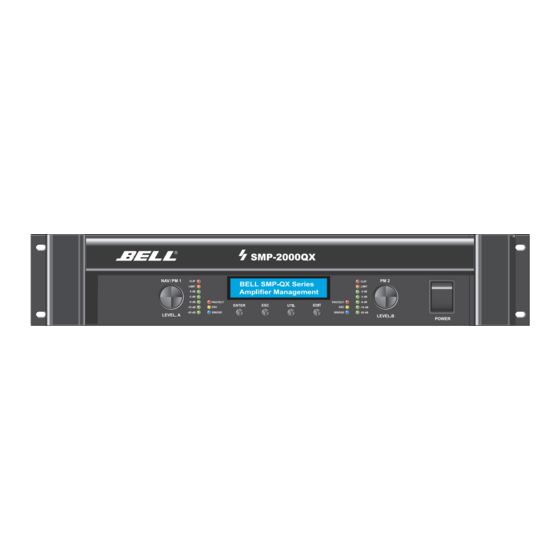
Operational features - Front - Operational features - Front - PM1/NAV: navigates within the various menus (Utility, Edit) PM1: sets any selected parameter value sets LEVEL of channel A, when function Level Pot in System Utility is active PM2: sets selected parameter values sets LEVEL of channel B, when function Level Pot in System Utility is active Enter button: confirms any edited parameter... - Page 4 TREE: UTILITY MENU TREE: UTILITY MENU -- UTILITY BUTTON -- -- UTILITY BUTTON -- UTILITY MENU: UTILITY MENU: UTILITY MENU: UTILITY MENU: UTILITY MENU: UTILITY MENU: UTILITY MENU: UTILITY MENU: UTILITY MENU: UTILITY MENU: -- System Utilities -- -- System Utilities -- -- Program Utilities -- -- Program Utilities -- -- Interface Utilities --...
- Page 5 Sub Menu: System Utilities Sub Menu: System Utilities ESC (quit) System Setup System Setup SYSTEM UTILITY: SYSTEM UTILITY: System Setup System Setup System Setup System Setup Enter Enter -- System Setup -- -- System Setup -- Setup: BRIDGE MODE Setup: BRIDGE MODE Setup: STEREO * Setup: STEREO * New Mode...
-
Page 6: System Utility
Set Default Values Set Default Values ESC (quit) SYSTEM UTILITY: SYSTEM UTILITY: Set Default Values Set Default Values Set Default Values Set Default Values Enter Enter -- Set Default Values -- -- Set Default Values -- (Enter) to confirm (Enter) to confirm Please Wait .. - Page 7 Channel Link Channel Link ESC (quit) SYSTEM UTIlity SYSTEM UTIlity Channel Link Channel Link Enter Channel Link Channel Link Enter -- Channel Link -- -- Channel Link -- Link : OFF Link : OFF Link : ON * Link : ON * Channel Link Channel Link Channel Link...
- Page 8 Ramp Function Ramp Function ESC (quit) Ramp Function Ramp Function Ramp Function Ramp Function SYSTEM UTILITY: SYSTEM UTILITY: Enter Enter Ramp : Disable Ramp : Disable Ramp : Enable * Ramp : Enable * -- Ramp Function -- -- Ramp Function -- Default setting of RAMP Function is Disable.
-
Page 9: Program Utility
Sub Menu: Program Utilities Sub Menu: Program Utilities Recall a Program Recall a Program ESC (quit) PROGRAM UTILITY: PROGRAM UTILITY: Recall a Program Recall a Program (Enter) to Recall (Enter) to Recall Enter Enter Enter -- Recall a Program -- -- Recall a Program -- 01: ARENA VIENNA 01: ARENA VIENNA... - Page 10 Save a Program Save a Program ESC (quit) PROGRAM UTILITY: PROGRAM UTILITY: Save a Program Save a Program Save a Program Save a Program Enter Enter -- Save a Program -- -- Save a Program -- 01: ARENA VIENNA 01: ARENA VIENNA 14: King Albert Hall 14: King Albert Hall Set Progam Name...
- Page 11 Sub Menu: Interface Utilities Sub Menu: Interface Utilities Interface Utilities Interface Utilities ESC (quit) Interface UTILITY: Interface UTILITY: Interface Setup Interface Setup Interface Setup Interface Setup Enter Enter -- Interface Setup -- -- Interface Setup -- Remote ID Num : 02 Remote ID Num : 02 Remote ID Num : 01 Remote ID Num : 01...
- Page 12 Sub Menu: Security Utilities Sub Menu: Security Utilities Show Parameter Show Parameter ESC (quit) Security UTILITY: Security UTILITY: Parameter will Parameter will Parameter will Parameter will Enter Enter -- Show Parameter -- -- Show Parameter -- be shown be shown not be shown not be shown The default setting for ‚SHOW PARAMETER‘...
- Page 13 Your personal, 6-digit password is the key to the SMP_QX amplifier. Should the password be forgotten, the unit may only be unlocked by BELL This parameter will not be stored with command ‚Save Program to PC und Save Program to Device‘...
- Page 14 Sub Menu: Noise Generator Utilities Sub Menu: Noise Generator Utilities Noise Level & Type Noise Level & Type ESC (quit) Noise Level & Type Noise Level & Type Noise Generator Utility: Noise Generator Utility: Noise Level & Type Noise Level & Type Noise Level &...
-
Page 15: Rms Limiter
STARTING SCREEN STARTING SCREEN -- EDIT Channel A & Channel B -- -- EDIT Channel A & Channel B -- NOISE ON / OFF NOISE ON / OFF GAIN GAIN NAME NAME SOURCE SOURCE LEVEL LEVEL RMS LIMITER RMS LIMITER PEAK LIMITER PEAK LIMITER DELAY... - Page 16 EDIT PARAMETERS CHANNEL A & CHANNEL B EDIT PARAMETERS CHANNEL A & CHANNEL B Pink Noise to Channel A Pink Noise to Channel A ESC (quit) Pink Noise to CH.A Pink Noise to CH.A Pink Noise to CH.A Pink Noise to CH.A Pink Noise to CH.A Pink Noise to CH.A Enter...
- Page 17 Source Source ESC (quit) OUT: A Low-A Source OUT: A Low-A Source OUT: A Low-A Source OUT: A Low-A Source OUT: A Low-A Source OUT: A Low-A Source Enter aSource = InA aSource = InA Source = InA Source = InA aSource = InB aSource = InB Default setting for SOURCE is ‚InA‘...
- Page 18 Level Level ESC (quit) Out: A Out: A Low-A Level Low-A Level Out: A Out: A Low-A Level Low-A Level Out: A Out: A Low-A Level Low-A Level Enter Level = 0.0dB Level = 0.0dB aLevel = -6.0dB aLevel = -6.0dB aLevel = 0.0dB aLevel = 0.0dB Default setting for LEVEL is 0.0dB.
- Page 19 Release time is defined as the time it takes the limiter to increase the signal gain by a defined value. Normally, this value will be defined at 20dB. Since the SMP_QX Power Amplifiers feature 2 separate limiters (RMS Limiter plus Peak Limiter), there will be an interference (in dynamics), when both limiters work on the same threshold level.
- Page 20 Polarity Polarity ESC (quit) Out:A Low-A Polarity Out:A Low-A Polarity Out:A Low-A Polarity Out:A Low-A Polarity Out:A Low-A Polarity Out:A Low-A Polarity Enter Polarity = Normal Polarity = Normal aPolarity = Invert aPolarity = Invert aPolarity = Normal aPolarity = Normal The default setting of polarity is normal (in phase) In the given example, polarity was changed to INVERT (out of Phase).
- Page 21 Type=BELL EQ f=1.00kHz Type=BELL EQ f=1.00kHz Default setting of EQ Type is BELL EQ. The default setting of EQ Frequency is 1.00kHz In the given example, EQ Type is changed to High Shelving Filter (1st. order) and Shelving EQ frequency is changed to 3.06kHz.
- Page 22 SMP_QX rear panel features SMP_QX rear panel features RS485 Ground Lift cuts the pcb GND from PIN1 of the XLR(f) socket. PIN1 of the XLR(m) Link socket is not Speaker Output connected to PIN1 of CHANNEL A the XLR(f) socket. CHANNEL B BRIDGE For Speakon Type...
- Page 23 - Since a PC will not provide an RS485 interface, an optional USB-to-RS485 interface will be necessary. - This DSM-RS interface may be obtained from BELL. - Connect the interface to any free USB port of your PC - The RS485 side of the interface (XLR m) will be connected to the RS485 socket on the rear side of the SMP_QX amp (device).
- Page 24 Selecting a COM Port Selecting a COM Port the required COM Port to be used will be displayed in your Windows System Control. The following steps have to be made: - Open the System Control Menu in your PC - System - Hardware - Device Manager - Interface (COM and LPT)
- Page 25 In this window, you may select the ID numbers for up to 10 devices which you intend to control. If any change of ID number is required, use the button ‚Configure ID Device‘ All devices which are connected within the system are filed in the Select ID list. In order to change its ID number, you may select any device from the Select ID list.
- Page 26 A double clic on any listed device (ID list) will activate the connection between device and PC. The selected device (in example device Nr.1) will answer with the following LCD screen: System Online System Online BELL SMP-QX ID (01) BELL SMP-QX ID (01) The PC will reply by opening the main window + the utility window.
- Page 27 Commands (exclusive to PC software only) Commands (exclusive to PC software only) Load Program to PC Load Program to PC Load Program from PC Load Program from PC Load program from PC will load a complete program including all parameters from the PC into the active device window.
- Page 28 Save a Program to PC Save a Program to PC Save a program to PC will store all parameters shown in the active device window. A program will include all parameters with the exception of: -Noise generator on / off -EQ bypass (after loading the program, EQ bypass will be reset to OFF (EQ=active) -Power -Noise generator settings...
-
Page 29: Load Preset
System Power Amplifiers. Normally, a Preset will contain the settings for a specific loudspeaker system. Such presets may be composed by the user - or in case of BELL speaker systems - they may be obtained from the manufacturer. - Page 30 Save Preset to PC (from current output) Save Preset to PC (from current output) Save preset to PC will store an output channel preset from the active output channel to the PC. A preset will include all parameters with the exception of: -Noise generator on / off -EQ bypass (after loading the program, EQ bypass will be reset to OFF (EQ=active) -Routing...
- Page 31 Copy Program Data Copy Program Data The Copy Data command will copy all data (except device name and password) of the active device to the selected units. The COPY DATA window will show name and ID of the device (Source). In order to Copy DATA from the Source device to any one of the connected, devices, these have to be selected as destination devices by ticking the click boxes.
- Page 32 Device LINK Device LINK The device link function will define the active window as MASTER. Any device which is selected as SLAVE will automatically execute all functions of the Master. It is possible to define a multiple number of MASTERS. Of course, each Slave (ID) may only be controlled by one Master.
- Page 33 The button ‚Link Master to Slave‘ will activate this procedure and close the device link window. All slave windows will automati- cally be closed. The Device Link button will be shows as Master / ID button (green). The Device Link button of the slaves will show Slave / ID (orange).
- Page 34 Output Channel window Output Channel window View RMS Limiter View RMS Limiter Graphic shows the function of a limiter with parameters threshold and ratio. In the PC software, both EQ parameters BW and Q will be shown. Q will not be shown in the device display.
- Page 35 Example refers to activated window (CH.A) Show Cursor will issue a cursor for each EQ 1...8 in the frequency response graphic moving this handle will change frequency and amplitude ONLY OUT will show the frequency response graph of the selected output only Out + InA shows the graph of the mathematical addition of Input Gain CH.A + the frequency response of the Output (CH.A)
- Page 36 Lock Preset Lock Preset Lock Preset will lock some parameters of an output channel (preset), in order to avoid manipulation. This function may only be activated / deactivated by the manufacturer. Locked parameters will not be displayed in the freq. resp. graphic.
- Page 37 IO / Meter / Delays Window IO / Meter / Delays Window Utility Window Utility Window...
- Page 38 High-Pass Filter, Low-Pass Filter, White- u. Pink Noise Generator, 8-Band EQ, Peak- u. RMS Limiter. Sämtliche Parameter werden direkt oder mittels BELL QX Audio Remote Control Software editiert und gespeichert. RS485 Remote Control & Software Über die RS485 Schnittstelle und...
- Page 39 Front Panel SMP.QX Series Program Utilities SMP.QX amplifiers combine the well Program Recall Input-Level Control (Ch. A&B) ● ● proven BELL Class H technology with Program Save ● Level-Regler (Kanal A&B) Program Delete today's most advanced SMPS switch- ● Mains switch ●...
Need help?
Do you have a question about the SMP QX Series and is the answer not in the manual?
Questions and answers