Advertisement
Quick Links
Pack 04 | Build Instructions
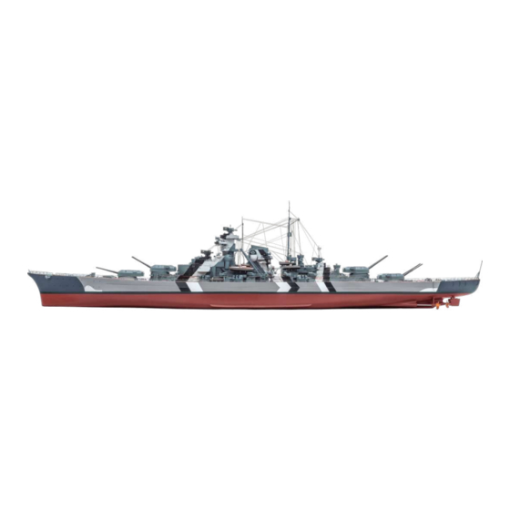
Your 1:200 scale model of the legendary battleship Bismarck is packed with
intricate details which precisely replicate every aspect of this state-of-the-
art warship. Each piece has been created using premium quality materials to
bring maximum enjoyment during your complete build.
STAGE 33: MOTOR FOR THE FORWARD
RADAR EQUIPMENT
STAGE 34: RADAR CONTROL CENTRE
STAGE 35: A KEEL SECTION AND
A DISPLAY STAND
STAGE 36: MOTOR FOR THE FORETOP
RADAR INSTALLATION
STAGE 37: THE FORETOP RADAR
AND A PORT HULL SECTION
© 2020 Hachette Partworks Ltd.
North America Edition by Agora Models
In your fourth model pack, you will assemble:
STAGE 38: THE FORETOP RADAR
AND A STARBOARD HULL SECTION
STAGE 39: THE NEXT HULL SECTION
STAGE 40: FIRE CONTROL POST DETAILS AND
SEARCHLIGHT DECK
STAGE 41: THE NEXT SECTION OF HULL
STAGE 42: THE SIXTH KEEL SECTION
STAGE 43: ADMIRAL'S BRIDGE
STAGE 44: THE UPPER MAST DECK
Advertisement

Related Manuals for Hachette Agora Bismarck Pack 04


Summary of Contents for Hachette Agora Bismarck Pack 04
- Page 1 STAGE 41: THE NEXT SECTION OF HULL RADAR INSTALLATION STAGE 42: THE SIXTH KEEL SECTION STAGE 37: THE FORETOP RADAR STAGE 43: ADMIRAL’S BRIDGE AND A PORT HULL SECTION STAGE 44: THE UPPER MAST DECK © 2020 Hachette Partworks Ltd. North America Edition by Agora Models...
- Page 2 Advice from the experts Spare screws are included with each part. Occasionally, you may be instructed to keep spare or unused screws for a later stage. Keep these spares in a safe place and label them correctly. Please make sure you don’t mix up the screws. They look quite similar, but the threads do vary slightly.
- Page 3 STAGE 33 MOTOR FOR THE FORWARD RADAR EQUIPMENT 33-01 33-02 COMPONENTS CHECKLIST Motor for the forward radar Three 1.7 x 6 mm PB screws 33-01: Cable label 33-02: . PREPARING THE RADAR MOTOR 33-02 33-01 Take the motor with attached cable 33-01. Remove Completed work 33-02 the cable label...
- Page 4 STAGE 34 RADAR CONTROL CENTRE 34-04 34-02 34-03 34-05 34-01 34-08 34-07 34-06 34-14 34-12 34-11 34-10 34-09 34-13 PB 1.7x4 PB 2x5 COMPONENTS CHECKLIST Control centre Small parts (L) 34-01: 34-07: Small metal parts 34-13: Radar unit Small parts (M1–M3) 34-02: 34-08: Radar antenna...
- Page 5 34-02 34-02 Cut the two radar arms from the frame 34-06. Glue Fit the second radar arm in place on the other side to the radar unit 34-02, ensuring that of the radar unit 34-02, ensuring it is pointing in the the first arm it is pointing in the right direction (see step 4).
- Page 6 33-01 PB 2x5 PB 1.7x6 34-04 PB 2x5 34-04 Fit the mounting plate 34-04 onto the bottom of the Insert the shaft of the motor 33-01 into the centre of 34-11 control centre and fix in place with the three (not shown) and fix the motor to the 5 mm screws.
- Page 7 34-01 34-01 Identify the two ladders and cut them from part Glue the second ladder in place on the port side of 34-13. Glue the first ladder the control centre 34-01. on the starboard side of the control centre 34-01. 29-01 from part 34-13.
- Page 8 34-01 Taking care that the parts do not fly off, cut part Cut four parts and one part from the frame. and three parts from the frame 34-05. Glue them Glue them around the edge of the control centre to the top of the control centre 34-01. 34-01 as shown.
- Page 9 STAGE 35 A KEEL SECTION AND A DISPLAY STAND 35-01 35-03 35-02 35-05 35-04 PM 2x4 PB 2x5 COMPONENTS CHECKLIST Fifth keel section 35-01: Right display stand 35-04: Connecting piece 35-02: support 35-03: Left display stand support Base of display stand Five 2 x 4 mm PM screws 35-05: .
- Page 10 34-07 Fit first two parts from the frame on each side Fit the two remaining parts in the forward corners of the lower mast deck, as shown. Fix in place with a of the bridge deck and glue in place. little superglue.
- Page 11 . ASSEMBLING THE SUPERSTRUCTURE ELEMENTS Take the control centre assembly from the previous When fitting the control centre, take care not to stage and check the fit in the recess on the lower damage the parts that are already in place. Press mast deck as shown.
- Page 12 . FITTING THE NEXT KEEL SECTION PM 2x4 35-02 27-01 PM 2x4 35-02 35-02 35-02 Fit the connecting piece over the two raised Fix part to the keel assembly using two sockets on the keel section 27-01, as indicated. Have PM 2 x 4 mm screws as shown.
- Page 13 Next, fit the pegs on the other bracket 35-03 into the corresponding holes in the base 35-05, as shown. 35-03 35-05 Fit the display stand 35-05 under the hull of your model and push it aft as far as possible. Note: When positioning the display stand, make sure that the ‘front’...
- Page 14 STAGE 36 MOTOR FOR THE FORETOP RADAR INSTALLATION 36-01 36-02 COMPONENTS CHECKLIST Motor for the radar Three 1.7 x 6 mm PB screws 36-01: installation Cable label 36-02: . PREPARING THE RADAR MOTOR 36-01 36-02 Take the motor with attached cable 36-01. Remove Completed work the cable label 36-02...
- Page 15 STAGE 37 THE FORETOP RADAR AND A PORT HULL SECTION 37-02 37-01 37-05 37-04 37-06 37-03 37-08 37-10 37-09 37-07 37-11 PM 2x4 PB 2x5 PB 1.7x4 COMPONENTS CHECKLIST Lower port hull section Foretop command 37-01: 37-06: 37-10: post attachment Radar unit Two shafts 37-02:...
- Page 16 . THE RADAR UNIT 37-04 37-07 37-04 37-07 37-04 37-07 in place on the top of part 37-04. Put the foretop command post attachment Fix the deck 37-07 your work surface. Take the deck and check the fit on the top of part 37-04. Apply superglue to the 37-07.
- Page 17 37-05 36-01 37-05 37-04 Take the base plate 37-05 and fit it over the cogs. Take the motor from the previous stage. Fit the shaft PB 2 x 5 mm of the motor into the recess in cog 37-10, so that the Fix in place with three screws so that the cogs are held in place.
- Page 18 STAGE 38 THE FORETOP RADAR AND A STARBOARD HULL SECTION 38-02 38-01 38-04 38-03 COMPONENTS CHECKLIST Lower starboard hull Small accessories (1–5) 38-01: 38-03: section Deck 38-04: Foretop command post 38-02: Four PM 2 x 4 mm screws gallery . FITTING THE NEXT HULL SECTION 38-01 38-01 30-01...
- Page 19 . ACCESSORIES FOR THE FORETOP CONTROL POST 38-02 38-04 38-02 38-04 38-04 Take the deck and fit it into the foretop This shows the deck in place. If it is loose, fix in place command post gallery 38-02, as indicated by the with a little superglue.
- Page 20 37-07 37-07 Cut the three parts 3, from the frame 38-03. Identify Turn the foretop around so that you can fit the second the fixing point for the first part 3, on the recess part 3, in one of the recesses in the aft corners of the on the forward end of the deck 37-07.
- Page 21 STAGE 39 THE NEXT HULL SECTION 39-02 39-01 COMPONENTS CHECKLIST Upper port hull section Five 2 x 4 mm PM screws 39-01: Connecting piece 39-02: . FITTING THE NEXT HULL SECTION 39-01 39-01 31-01 37-01 Take the hull assembly from stage 38. Align the holes in Fix the hull section 39-01 in place with two...
- Page 22 Fit the connecting piece 39-02 over the raised screw sockets on either 39-01 side of the join between parts 31-01 39-01 and 31-01. 39-02 Fix the connecting piece 39-02 in place 39-02 with two 2 x 4 mm screws. Completed work Another panel has now been added to the hull section.
- Page 23 STAGE 40 FIRE CONTROL POST DETAILS AND SEARCHLIGHT DECK 40-02 40-01 40-03 40-04 40-06 40-05 40-07 40-12 40-11 40-10 40-14 40-08 40-09 40-13 COMPONENTS CHECKLIST Upper superstructure, Decking Cooling coil 40-01: 40-05: 40-10: left half Four ZAG artillery Rangefinder rails 40-06: 40-11: Upper superstructure,...
- Page 24 . ASSEMBLING THE FIRST SEARCHLIGHT 40-13 40-08 Carefully cut the base of the searchlight from Cut the searchlight body from frame 40-07. Take the frame 40-07. Pass the LED on the end of cable 40-13 40-08 and fit it into part 1. The inset searchlight glass through part 3.
- Page 25 40-13 40-13 Cut the headlight arm from the frame 40-07. Fit the Apply a little superglue to the pegs on part 40-13 into the recess in part 6. Make searchlight cable stick them in place in the holes on part so that the sure you have part the right way round, as shown.
- Page 26 40-04 40-05 40-03 40-05 40-13 Stick the decking 40-05 in place on the searchlight Hold the searchlight in place until the glue is firmly platform 40-03. Apply a little glue to the base of the set. Apply a little superglue to the two pegs on the 40-13 40-04 searchlight and gently pull the cable...
- Page 27 . DETAILS FOR THE FORETOP FIRE CONTROL POST 37-02 37-02 40-09 40-10 37-02 40-10 Take the radar assembly unit (assembled in After checking the fit, glue the cooling coil stage 38). After checking the fit, glue the ladder support place behind the port rangefinder arm, as shown. 40-09 to the radar unit on the foretop fire control post.
- Page 28 STAGE 41 THE NEXT SECTION OF HULL 41-01 41-02 COMPONENTS CHECKLIST Starboard upper Connector Five 2 x 4 mm PM 41-01: 41-02: hull section screws FITTING THE HULL SECTION Put the hull structure on your worktop. Take the starboard upper hull section 41-01 41-01 and fit it against the starboard...
- Page 29 Use two screws to fix section 41-01 section 38-01, as shown. 41-01 38-01 Fit the screw holes on the connector 41-02 over the screw sockets on parts 41-01 32-01 32-01 and 41-01. Fix in place with two 2 x 4 mm screws. 41-02 Completed work Another section of the hull has now...
- Page 30 STAGE 42 THE SIXTH KEEL SECTION 42-02 42-01 COMPONENTS CHECKLIST Sixth keel section Five 2 x 4 mm PM screws 42-01: Connector 42-02: FITTING THE KEEL SECTION 35-01 35-01 42-02 42-02 Put the hull structure on your worktop. Fit the sockets Use two screws to fix the connector 42-02...
- Page 31 Bring the edge of the keel section 42-01 up beneath the connector 42-02 so that 42-01 the raised screw sockets on part into the sockets on part 42-02. 35-01 42-01 42-02 Use two screws to fix connector 42-02 to keel section section 42-01, as shown.
- Page 32 STAGE 43 ADMIRAL’S BRIDGE 43-01 43-04 43-02 43-03 43-05 43-06 43-07 43-10 43-09 43-08 COMPONENTS CHECKLIST Admiral’s bridge deck Decking 43-01: 43-06: Signalman’s shelter Windows 43-02: 43-07: Shelter Railings 43-03: 43-08: Three 1.7 x 4 mm PWB PWB: : Gratings Light cable 43-04 43-09:...
- Page 33 43-01 Repeat the previous two steps to cut parts Take the admiral’s bridge deck 43-01 and identify the from the frame and fix together. Note the orientation fixing point for the grating assembly on the of the parts. port side. Apply a tiny drop of superglue to the tab on part and fix in place as indicated by the arrow.
- Page 34 . LIGHTING FOR THE ADMIRAL’S BRIDGE 43-09 43-07 43-07 43-07 43-07 Take the windows of the admiral’s bridge and fit Fit part over the recess in part to hold the 43-09 the LED on the end of cable into the recess. Cut LED in place.
- Page 35 : ASSEMBLING THE ADMIRAL’S BRIDGE from frame 43-08. Identify the Cut the railing Identify the next two bend points (red arrows) and indents on either side of the centre point of the bend the railings outwards at right angles. Check the railings (see detail image).
- Page 36 43-01 43-09 43-06 43-06 43-09 43-01 Glue the last section of railing in place along the Feed the connector cable through port side of the decking 43-06. (inset). Apply a little superglue to the tabs on the base 43-06 and fix into the recesses in deck 43-01 aligns with the front of the deck 43-01.
- Page 37 STAGE 44 THE UPPER MAST DECK 44-02 44-01 44-03 44-06 44-06 44-05 44-04 44-09 44-08 44-07 COMPONENTS CHECKLIST Upper mast deck Lower section of the Ammunition hoist 44-01: 44-04: 44-06: conning tower (port) Accessories for the upper Port railing 44-02: 44-07: mast deck Lower section of the...
- Page 38 44-05 44-04 44-04 44-01 44-04/44-05 Glue the two sections of the conning tower together Check the fit of assembly in the opening so that the pegs on part 44-05 fit into the sockets on of the upper mast deck 44-01, noting the orientation, part 44-04, as shown.
- Page 39 44-06 44-01 Fit the second part in place through the opening in Glue the assembled ammunition hoist 44-06 in place part 2, and glue the loop in place on the horizontal at the front of the upper mast deck 44-01 as shown.
- Page 40 44-07 44-08 44-01 Turn the assembly around again and take the port Turn the assembly round and glue the starboard railing, 44-07. Check the fit around the front port side 44-08 railing in place around the starboard side of the of the upper mast deck 44-01 and use a few drops of...
Need help?
Do you have a question about the Agora Bismarck Pack 04 and is the answer not in the manual?
Questions and answers