Advertisement
Quick Links
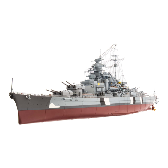
Your 1:200 scale model of the legendary battleship Bismarck is packed with
intricate details which precisely replicate every aspect of this state-of-the-
art warship. Each piece has been created using premium quality materials to
bring maximum enjoyment during your complete build.
STAGE 09: GEARBOX FOR THE
BOW ANCHORS: 2
STAGE 10: THE SECOND SECTION
OF THE UPPER DECK
STAGE 11: THE PORT HULL AND SUPPORT STAND
STAGE 12: GEARBOX FOR THE
FORWARD GUN TURRET
STAGE 13: HINGED SUPPORTS FOR
THE BREAKWATER
STAGE 14: MOTOR FOR THE FORWARD
GUN TURRET
© 2020 Hachette Partworks Ltd.
North America Edition by Agora Models
Pack 02 | Build Instructions
In your second model pack, you will assemble:
STAGE 15: HULL ASSEMBLY AND SUPPORTS
FOR THE FORE BREAKWATER
STAGE 16: FORWARD GUN ELEVATION MOTOR
STAGE 17: WIRING FOR
THE FORWARD TURRET
STAGE 18: TESTING THE
WIRING OF THE TURRET
STAGE 19: THE JACKSTAFF
AND BOW LIGHT
STAGE 20: ANOTHER SECTION OF THE HULL
Advertisement

Related Manuals for Hachette AGORA MODELS BISMARCK


Summary of Contents for Hachette AGORA MODELS BISMARCK
- Page 1 STAGE 13: HINGED SUPPORTS FOR STAGE 19: THE JACKSTAFF THE BREAKWATER AND BOW LIGHT STAGE 14: MOTOR FOR THE FORWARD STAGE 20: ANOTHER SECTION OF THE HULL GUN TURRET © 2020 Hachette Partworks Ltd. North America Edition by Agora Models...
- Page 2 Advice from the experts Spare screws are included with each part. Occasionally, you may be instructed to keep spare or unused screws for a later stage. Keep these spares in a safe place and label them correctly. Please make sure you don’t mix up the screws. They look quite similar, but the threads do vary slightly.
-
Page 3: Components Checklist
STAGE 09 GEARBOX FOR THE BOW ANCHORS: 2 9-02 9-03 9-04 9-01 9-05 9-07 9-06 COMPONENTS CHECKLIST 9-01: Two cogs with 9-04: shafts 9-05: Two shafts Eleven 2 x 6 mm 9-02: Double cog with screws 9-06: Anchor motor shaft 9-07: Switch 9-03:... - Page 4 9-05 9-04 9-05 9-03 9-03 9-04 onto the shaft 9-05. Fit the second 9-03 onto shaft 9-05. Make sure that Fit the cog Fit the cog 9-05 shaft into the hole near the end of the gearbox the peg (indicated by the arrow) is at the angle as shown.
- Page 5 9-03 9-07 When fitting the anchor motor 9-06 into the Insert the switch 9-07 in the gearbox housing gearbox, make sure that the cables run upwards so that its pin is to the left of the peg on cog 9-03 (as indicated by the arrow).
- Page 6 5-05 1-04 1-04 9-01 9-02 1-02 5-05 9-01 5-05 Apply a little superglue to the bottom of the Fit the two capstans assembled in stage 05, 1-04 9-01 capstan head supplied with stage 01. Glue on the splines on the ends of shafts (see also part 1-04...
- Page 7 . ATTACHING THE TWO SIDE BOW ANCHORS Take out the two anchors assembled in stage 07. Take one of the anchor chains 7-06 and a ring 7-07. Carefully lever the ring open so that you can thread it through the last link in the chain. You may find it helpful to use tweezers and a magnifying glass.
- Page 8 STAGE 10 THE SECOND SECTION OF THE UPPER DECK 10-01 10-02 10-08 10-04 10-09 10-10 10-05 10-03 10-07 10-06 COMPONENTS CHECKLIST 10-01: Second section 10-03: Fore breakwater 10-07: Vent of the upper 10-04: 10-08: Vent Hatch deck Five 2 x 6 mm 10-05: Two skylights 10-09:...
- Page 9 DETAILS FOR THE SECOND UPPER DECK SECTION 10-01 10-03 10-03 10-03 10-03 Place the front breakwater upside down in Fix the breakwater in place so the tabs on front of the upper deck section 10-01. Apply 10-03 fit into the recesses at the front edge of the thick superglue to the four tabs on the upper deck section 10-01.
- Page 10 10-08 10-10 10-08 Take the hatch and glue it in place behind At the very back of the upper deck section identify 10-10 the handwheel on the upper deck section as the recesses for the five identical skylights shown. behind the barbette. Glue them in place. ASSEMBLING THE UPPER DECK PARTS 1-01 1-01...
- Page 11 STAGE 11 THE PORT HULL AND SUPPORT STAND 11-01 11-02 11-03 11-04 COMPONENTS CHECKLIST 11-01: Second port hull 11-03: Hull support (2) Four 2 x 4 mm NOTE: You will also need section screws additional screws 11-04: Two support supplied with Stage 04. 11-02: Hull support (1) bases...
- Page 12 Check how the assembly 4-04/11-01 fits on the parts of the hull that have 4-04 already been assembled. The upper 11-01 4-04 edge of part should be flush with the bow section of the hull (see blue arrows) and there should not be a gap where the upper sections of the hull butt up against the section of the hull below the waterline.
- Page 13 11-04 11-03 11-03 11-02 11-04 11-04 The photo shows the the assembled support bracket Fit the pegs on the lower edge of 11-03 into the holes of the second support base 11-04. for the bow of the model. Place the second support 11-03 11-04 and the support base...
- Page 14 STAGE 12 GEARBOX FOR THE FORWARD GUN TURRET 12-04 12-01 12-03 12-02 12-07 12-05 Note: The screws are the same type but have different 12-06 diameters and threads. 12-09 12-08 12-10 2 x 6mm COMPONENTS CHECKLIST 12-01: 12-06: 2.3 x Cog 1 Gearbox housing 12-02:...
- Page 15 2.3 x 2-01 2-02 10-02 12-07 2.3 x 6 mm 2-01 on the barbette 10-02, Place the gun turret Holding the gun turret in position, turn the 2-02 guiding the cable through the hole. At the same deck over again. Fix the turret base to cog time, hold cog 12-07...
- Page 16 12-09 12-02 12-05 12-06 Fit the shaft 12-09 into the central hole in cog Fit the other half of the gearbox housing 12-05 12-02 as shown. over part 12-06 as indicated. 12-05 2-08 2 x 6 mm 12-03 12-06 12-06 12-10 12-03 Fix the two halves of the gearbox housing...
- Page 17 STAGE 13 HINGED SUPPORTS FOR THE BREAKWATER 13-04 13-03 13-02 13-01 13-05 COMPONENTS CHECKLIST 13-01: Third keel section 13-04: Right gearbox mounting 13-02: Supports x 10 bracket 13-03: 13-05: Left gearbox mounting bracket Hinge joints x 10 Seven 2 x 4 mm screws MOUNTING THE GUN ELEVATION GEARBOX 12-06 12-06...
- Page 18 12-05 12-05 13-03 13-03 13-03 On the other side of the gearbox, fit the left Fix the gearbox mounting bracket to the 13-03 12-05 gearbox mounting bracket on the pegs on gearbox housing with a screw as the gearbox housing 12-05. shown.
- Page 19 13-02 13-05 1-01 13-05 Repeat steps 1 and 2 with the remaining nine Apply a drop of superglue to the bottom of a supports 13-02 and joints 13-05, to make a total hinge joint 13-05 (see inset). Glue it in the of 10 hinged supports.
- Page 20 STAGE 14 MOTOR FOR THE FORWARD GUN TURRET 14-01 Note: The gun turret motor is a step motor, more commonly called a stepper motor, that controls the rotation of the turret in small steps. COMPONENTS CHECKLIST 14-01: PWB: Gun turret motor Three 2.3 x 5mm screws FITTING THE GUN TURRET MOTOR Take the gun turret motor 14-01.
- Page 21 Place the deck 1-01 upside down on your work surface, taking care not to cause any damage. Position 14-01 12-07 the motor on the underside of the deck, as shown, so that the 12-08 screw holes in the tabs on the sides of the motor are aligned with the raised screw sockets on the deck.
- Page 22 STAGE 15 HULL ASSEMBLY AND SUPPORTS FOR THE FORE BREAKWATER 15-01 15-03 15-02 COMPONENTS CHECKLIST 15-01: 15-03: Port lower hull section Supports (x10) 15-02: Hinge joints Three 2 x 4mm screws (x10 on a single fret) JOINING THE KEEL AND LOWER HULL SECTIONS 13-01 Take the third keel section (supplied with stage 13).
- Page 23 Fix the two parts of the hull, 13-01 and 15-01, together with the two screws as shown. 15-01 Store the assembly safely. It will be needed again in a later stage. 13-01 . FITTING THE LAST 10 HINGED SUPPORTS FOR THE FORE BREAKWATER 15-02 Remove a hinge joint...
- Page 24 Working from the middle of the deck towards the starboard side, glue the hinge joints 15-02 in the recesses in the deck 1-01. The metal 10-03 15-03 supports should lean up against the breakwater 10-03. 15-03 15-02 1-01 Continue working across the deck to the outer edge so that all 10 hinged supports are glued in place.
- Page 25 STAGE 16 FORWARD GUN ELEVATION MOTOR 16-01 COMPONENTS CHECKLIST 16-01: Elevation motor Three 1.7 x 6 mm screws . FITTING THE ELEVATION MOTOR Take the elevation motor 16-01. Check how the shaft of the motor fits into the cog 12-02, as indicated by the arrow.
- Page 26 Fit the elevation motor 16-01 on the gearbox housing 12-06 so that the shaft of the motor engages with the cog 12-02. Check that the motor is 12-02 the right way round, with the cables 12-06 running towards the aft of the ship, 16-01 as indicated by the arrow.
- Page 27 STAGE 17 WIRING FOR THE FORWARD TURRET 17-02 17-01 COMPONENTS CHECKLIST 17-01: Circuit board box Four 2.3 x 6 mm screws 17-02: Cable tie . FITTING THE FIRST CIRCUIT BOARD BOX 17-01 Take the circuit board box and check how it fits on the 7-01 gearbox housing 7-01.
- Page 28 17-01 7-01 17-01 17-01 When the circuit board box is in the Fix the circuit board box to the gearbox 7-01 correct position, the screw holes will align with housing using three screws. Support the screw sockets on part 7-01. deck carefully as you fix the screws in place.
- Page 29 9-07 9-07 9-07 The next step is to fit the cable from the switch Plug the cable fully into port 3 of the circuit 9-07. The notches on the connector plug should board box as shown. face downwards, with the yellow wire on the right. .
- Page 30 16-01 16-01 Thread the cable from the elevation motor 16-01 Bring cable 16-01 round to the side of the circuit through the large eyelet on the underside of the board box so that you can plug it in to port 8. upper deck.
- Page 31 . FITTING THE CABLE TIE 2-12 12-05 16-01 17-02 17-02 Take the cable tie 17-02 and wrap it around the Tighten the cable tie 17-02 around the two 16-01 2-12 two cables as indicated. cables. The cable tie should be roughly level with the two front screws of the gearbox housing 12-05 (indicated by the dotted line).
- Page 32 STAGE 18 TESTING THE WIRING OF THE TURRET 18-03 18-02 18-01 COMPONENTS CHECKLIST 18-01: 18-03: Tester box Circuit board cable (four wires) 18-02: Tester cable (three wires) CONNECTING THE TESTER TO THE BATTERY BOX Place the three parts on your worktop.
- Page 33 18-02 18-01 18-02 18-01 18-02 18-02 Plug the tester cable into the right port of the The photo shows the tester cable connected tester box 18-01. The notches face upwards with the to the right port of the tester box 18-01. orange wire on the right.
- Page 34 Switch the battery box 4-07 to “On“ (inset). The initialization will start automatically. During this sequence, the gun turret rotates to starboard and stops before returning to the original position. Note: During the initialization, the 18-01 functions of the tester box not available.
- Page 35 If you press the “S2“ button on the tester box 18-01 (inset), the anchor test will begin. The two anchor spools turn first in one direction, then in the other direction. As a result, both anchors are lowered a little and then raised up again. Depending on the position of the anchor chain, there may be a slight delay in starting.
- Page 36 STAGE 19 THE JACKSTAFF AND BOW LIGHT 19-02 19-01 19-08 19-10 19-09 19-03 19-06 19-04 19-05 19-07 COMPONENTS CHECKLIST 19-01: 19-04: 19-08: Third section of the upper deck Fibre optic cable guide LED cable 19-02: Barbette for the second 19-05: Fibre optic cable mount 19-09: Jackstaff...
- Page 37 PREPARE THE BOW LIGHT 1-01 19-07 19-09 19-04 Place the forward deck assembly upside down Insert one of the plugs 19-07 into the top end of 19-09 on your desktop, taking care not to cause any jackstaff (the end that is further away 19-04 damage.
- Page 38 ASSEMBLING AND CONNECTING THE BOW LIGHT 19-06 19-10 19-06 1-01 19-09 Turn the deck assembly 1-01 over and guide the Fit the support 19-06 on to the top of the 19-10 19-09 fibre optic cable through the hole in the jackstaff and slide it down the pole.
- Page 39 19-10 19-10 19-04 1-01 Fit the fibre optic cable 19-10 into the recesses Cut the fibre optic cable 19-10 at the point where it 19-04 on the guide and the bottom of the deck comes out of the second recess in the raised 1-01, as indicated by the three arrows.
- Page 40 19-08 19-08 17-01 Thread the free end of LED cable 19-08 through Plug the connector of the LED cable 19-08 into the eyelet on circuit board box 17-01. port 1 of the circuit board box. The black wire is on the right. TESTING THE BOW LIGHT Set the switch of the battery box 4-07...
- Page 41 STAGE 20 ANOTHER SECTION OF THE HULL 20-01 20-03 20-02 COMPONENTS CHECKLIST 20-01: Lower starboard 20-03: Starboard Seven 2 x 4 mm hull section connector PM screws 20-02: Port connector CONTINUING THE HULL ASSEMBLY 13-01 13-01 20-01 20-01 13-01/15-01 20-01 Take the hull assembly from stage 15.
- Page 42 Fix the hull section 20-01 to part 13-01 using two screws, as shown. 20-01 NOTE: The unevenness between the sections of the hull will disappear once the screws are fully tightened. 13-01 Take the bow hull assembly and stands from stage 11. Stand the bow section on the support stands.
- Page 43 Position the hull section completed in step 3 against the bow hull assembly and check that the parts are correctly aligned, with no gaps or unevenness between the sections. 6-02 20-01 20-02 20-03 Fix the connectors 15-01 20-01 to the hull sections using two 2 x 4 mm screws, as 15-01...
Need help?
Do you have a question about the AGORA MODELS BISMARCK and is the answer not in the manual?
Questions and answers