Advertisement
Quick Links
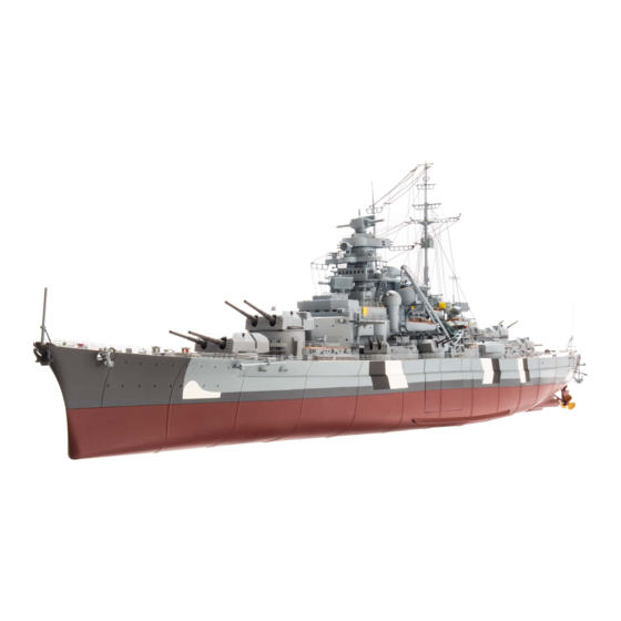
Pack 01 | Build Instructions
Your 1:200 scale model of the legendary battleship Bismarck is packed with
intricate details which precisely replicate every aspect of this state-of-the-
art warship. Each piece has been created using premium quality materials to
bring maximum enjoyment during your complete build.
In your first model pack, you will assemble:
STAGE 01: INITIAL PARTS OF THE UPPER DECK
STAGE 05: THE ANCHOR CAPSTANS AND
ANCHOR CHAIN OPENINGS
STAGE 02: THE FOREMOST 38CM GUN TURRET
STAGE 06: THE SECOND KEEL SECTION
STAGE 03: ON-BOARD AIRCRAFT
ARADO AR 196
STAGE 07: GEARBOX FOR THE
BOW ANCHORS I
STAGE 04: THE TWO CATAPULTS AND A
MOTOR TEST
STAGE 08: A SECTION OF THE HULL AND
DECK DETAILS
© 2020 Hachette Partworks Ltd.
North America Edition by Agora Models
Advertisement

Related Manuals for Hachette Agora Models BISMARCK


Summary of Contents for Hachette Agora Models BISMARCK
- Page 1 ARADO AR 196 STAGE 07: GEARBOX FOR THE BOW ANCHORS I STAGE 04: THE TWO CATAPULTS AND A MOTOR TEST STAGE 08: A SECTION OF THE HULL AND DECK DETAILS © 2020 Hachette Partworks Ltd. North America Edition by Agora Models...
- Page 2 PACK 1 Advice from the experts Spare screws are included with each part. Occasionally, you may be instructed to keep spare or unused screws for a later stage. Keep these spares in a safe place and label them correctly. Please make sure you don’t mix up the screws. They look quite similar, but the threads do vary slightly.
- Page 3 STAGE 01 INITIAL PARTS OF THE UPPER DECK COMPONENTS CHECKLIST 1-01: Forward section 1-01 of the upper deck 1-02: The warping winch baseplate 1-03: Two capstan drums 1-04: Capstan head 1-05: Capstan head 1-03 1-02 lower part 1-04 1-05 1-06: Two housings 1-07: The bow section...
- Page 4 NOTES BEFORE STARTING WORK Cut open the packaging carfully, to avoid damaging any parts. If you always take care. use a craft knife Remove the plastic parts from the frame by carefully cutting through the sprues that connect them. Take care that small parts do not ...
- Page 5 ASSEMBLING THE WARPING WINCH Take the baseplate of the warping 1-02 1-03 winch and the two capstan drums 1-03. Test fit the drums in the winch to see how they fit. Apply a tiny drop of superglue to the small end of each of the capstan drums using a cocktail stick.
- Page 6 ATTACHING THE BOLLARDS, HOUSINGS AND HATCHES Apply a little superglue to the 1-02 underside of the warping winch that you have just assembled and seat it firmly in the large recess in the upper deck 1-01. 1-02 1-01 The photo shows the warping winch 1-02 firmly glued in position.
- Page 7 1-08 The next two bollards glued firmly into position at the same place on the port (left) side of the upper deck. 1-08 Finally, glue the following parts to the front of the upper deck in the positions shown: the two remaining bollards 1-08, the small hatch 1-09 1-10.
- Page 8 STAGE 02 THE FOREMOST 38CM GUN TURRET 2-03 2-01 2-02 2-04 2-08 2-06 2-07 2-09 2-05 Due to variations in lighting during photography, occasionally 2-13 parts may appear a 2-10 different colour. 2-12 2-11 Keep any extra screws as spares. COMPONENTS CHECKLIST 2-01: 2-07:...
- Page 9 THE FRICTION CLUTCH 2-03 2-10 2-10 Take the two gun barrels 2-10 and the Repeat this process with the second barrel 2-10. connector 2-03. Apply a little superglue to the When gluing the two barrels, make sure that stud at the end of the first barrel and attach it they are exactly aligned, so they are parallel, to the connector.
-
Page 10: Assembling The Motor
ASSEMBLING THE MOTOR 2-04 2-04 2-06 2-06 Fit the upper part of the motor mounting 2-04 Turn the assembly over and fix the top of the on the cradle base plate 2-06. A stud on the 2-04 motor mounting in place with two screws through the cradle base plate 2-06. - Page 11 SECURING THE GUN BARREL ASSEMBLY IN THE TURRET 2-01 Take the turret housing 2-01 and turn it upside Make sure the gun barrel assembly is inserted down. Insert the gun barrel assembly into the correctly so that the two pins on the sides of the revolving housing, as shown.
- Page 12 STAGE 03 ON-BOARD AIRCRAFT ARADO AR 196 3-01 3-05 3-10 3-02 3-11 3-06 3-17 3-03 3-07 3-16 3-15 3-04 3-08 3-09 3-12 3-13 3-14 COMPONENTS CHECKLIST 3-01: Bow section of hull 3-07: Wings 3-13: Pilot’s seat 3-02: Front strut 3-08: Engine 3-14: Machine gun...
- Page 13 THE FUSELAGE, COCKPIT CANOPY AND WINGS OF THE SHIPBORNE PLANE 3-06 3-05 3-06 3-05 Take the two parts of the fuselage 3-05 and 3-06. Use Gently press the two halves of the fuselage a cocktail stick to apply a drop of superglue to the together to ensure that the fixing points remain studs on the inside of the top half of the fuselage.
- Page 14 3-12 3-16 3-13 3-14 In the cockpit, use a little superglue to stick the Apply superglue to the two studs at the bottom three accessories in place as shown: the control lever of the cockpit canopy 3-16 and glue it to the 3-12, the pilot’s seat 3-13 and the machine gun 3-14.
- Page 15 3-03 3-10 3-11 3-02 3-03 3-11 3-10 Align the two floats 3-10 3-11 as shown. Apply Apply superglue to the ‘feet’ of the front struts 3-02 superglue to the two ‘feet’ of the rear strut 3-03 and glue them into the sockets at the front of the two floats.
- Page 16 STAGE 04 THE TWO CATAPULTS AND A MOTOR TEST 4-01 4-03 You will need three AA batteries to test the circuit 4-07 board. These are 4-02 not supplied. 4-05 4-06 4-08 4-04 COMPONENTS CHECKLIST 4-01: Catapult tracks (x2) 4-04: First port hull section 4-07: Battery box 4-02:...
- Page 17 ASSEMBLING THE TWO CATAPULTS 4-02 4-02 4-08 4-01 4-08 4-02 4-08 4-02 Take four of the wheels 4-02 and two of the Take a catapult track 4-01 and insert one of the axles 4-08. Push-fit the axles into the back of 4-02 / 4-08 two wheel/axle assemblies into the...
-
Page 18: Testing The Motor
TESTING THE MOTOR 4-07 Place the battery box 4-07 on your worktop. Insert three AA batteries into the battery box as Remove the screw on the lid of the battery shown. Then replace the lid of the battery box. box and slide it open. 4-06 4-07 4-06... - Page 19 STAGE 05 THE ANCHOR CAPSTANS AND ANCHOR CHAIN OPENINGS 5-01 5-02 5-03 5-04 5-05 5-08 5-06 5-07 COMPONENTS CHECKLIST 5-01: 5-04: First hull section, Two capstan wheels starboard side 5-05: Two capstan drums 5-02: Hull section connector (red and green) 5-03: 5-06: 5-08:...
- Page 20 . FIT CHAIN GUIDE AND COVERS FOR ANCHOR CHAIN OPENINGS Take the forward section of the upper deck 1-01. You will also need 1-01 the covers for the anchor chain openings 5-03 and the two chain guides 5-08. Test the fit of the first 5-03 chain guide around the hole in front 5-08...
- Page 21 . ASSEMBLE THE TWO CAPSTANS 5-05 5-06 5-07 5-05 5-04 5-06 5-04 Take the green capstan drum 5-05, the wheel Turn the capstan shaft over and fit the green 5-04, the shaft 5-06 and the support 5-07. Apply 5-05 capstan drum onto the shaft as shown.
- Page 22 STAGE 06 THE SECOND KEEL SECTION 6-02 6-01 COMPONENTS CHECKLIST 6-01: Second keel section Three 2 x 4 mm screws 6-02: Connector for keel section (includes a spare) . ASSEMBLY OF THE SECOND KEEL SECTION Take the bow section 3-01 that you completed with the instructions in stage 3.
- Page 23 On the inside of the hull, where parts 3-01 6-01 meet, fit the connector 6-02 as shown. 6-02 3-01 6-01 Fix the connector in place so that it holds the two keel sections together using two screws. 6-02 Completed work The hull of your BISMARCK model has grown.
- Page 24 STAGE 07 GEARBOX FOR THE BOW ANCHORS I 7-01 7-02 7-05 7-06 7-03 7-04 7-07 7-08 7-09 COMPONENTS CHECKLIST 7-01: 7-03: 7-05: 7-07: Gearbox housing, Cross shaft Lengthwise shaft Two anchor rings lower part 7-04: Two anchor 7-06: Two anchor 7-08: Two anchor arms 7-02:...
- Page 25 Take one of the two anchor chains 7-04 7-06 and fit the ring on the end of the chain over the hub of the wheel at one end of the cross shaft 7-03. The arrow in the photo indicates where it should be fitted. 7-03 7-06 Take the first anchor chain reel...
- Page 26 . FIT THE CROSS SHAFT INTO THE GEARBOX HOUSING 7-06 7-03 7-03 7-02 7-02 Place the upper part of the gearbox housing Insert the cross shaft 7-03 into the holes in the 7-02 upper part of the gearbox housing 7-02. The on your worktop.
- Page 27 STAGE 08 A SECTION OF THE HULL AND DECK DETAILS 8-01 8-06 8-02 8-05 8-04 8-03 COMPONENTS CHECKLIST 8-01: 8-04: 8:06: Second starboard Two attachment Two platforms hull section points Seven 2 x 4 mm 8-02: Two roller fairleads 8-05: Two anchor screws 8-03:...
- Page 28 5-01 8-01 5-01/8-01 Take the assembled parts and fit to the Fix the hull sections together with five parts of the hull assembled earlier. The upper screws at the points indicated. edge of part 5-01 should be aligned with the bow section of the hull, as indicated by the arrow.
- Page 29 Check the fit of the anchor brackets 8-05 at the top of the anchor hawses. Apply a little superglue to the pegs on the brackets and fix in place. 8-05 8-05 At the rear of the forward section of the deck, fix the attachment points 8-04, one on each side, using a little superglue.
Need help?
Do you have a question about the Agora Models BISMARCK and is the answer not in the manual?
Questions and answers