Advertisement
Quick Links
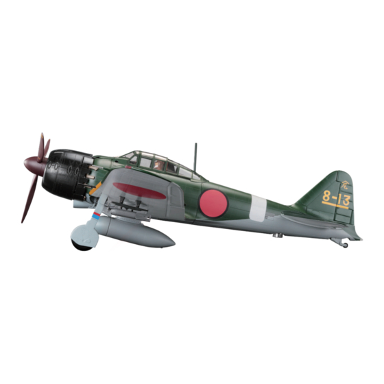
Your 1:18 model of the Japanese Zero is reproduced in the most exquisite
detail, with electronics allowing you to recreate aeronautical operations such
as take-off and landing, turning, firing and night combat. Lights, machine-gun
and propeller sounds bring your legendary fighter plane to life.
STAGE 37: INSTALLATION OF THE AILERON
OPERATING MECHANISM
STAGE 38: INSTALLING THE FLAPS
STAGE 39: INSTALLING THE LEFT AILERON
STAGE 40: INSTALLING A LEFT WING PART &
OUTER FRAME
STAGE 41: RIGHT MAIN LANDING GEAR BASE
© 2020 Hachette Partworks Ltd.
North America Edition by Agora Models
Pack 05 | Build Instructions
In your fifth model pack, you will assemble:
STAGE 42: RIGHT MAIN LANDING GEAR BASE
AND WHEEL
STAGE 43: ASSEMBLING THE RIGHT MAIN
LANDING GEAR (1)
STAGE 44: RIGHT WING FRAME
STAGE 45: ASSEMBLING THE RIGHT WING
Advertisement

Related Manuals for Hachette AGORA MITSUBISHI A6M ZERO FIGHTER


Summary of Contents for Hachette AGORA MITSUBISHI A6M ZERO FIGHTER
- Page 1 STAGE 39: INSTALLING THE LEFT AILERON STAGE 44: RIGHT WING FRAME STAGE 40: INSTALLING A LEFT WING PART & OUTER FRAME STAGE 45: ASSEMBLING THE RIGHT WING STAGE 41: RIGHT MAIN LANDING GEAR BASE © 2020 Hachette Partworks Ltd. North America Edition by Agora Models...
- Page 2 There are excellent videos showing how to build the Zero here. Advice from the experts Spare screws are included with each part. Occasionally, you may be instructed to keep spare or unused screws for a later stage. Keep these spares in a safe place and label them correctly. Please make sure you don’t mix up the screws.
- Page 3 組み立てガイ ド Stage 37: Installation of the Aileron Operating Mechanism In this stage we’ll be installing the operating mechanism which moves the Stage 37 Assembly aileron up and down to the wing base. This Aileron Operating Mechanism part of the plane will have electrical parts attached at a later point, so take due care.
- Page 4 組み立てガイ ド :Glue STEP 1 Installing the aileron operating mechanism :Don’t Glue 036-01 Align each of the four screw holes 037-01 Fit the aileron operating mechanism 037-01 into the main wing base frame 036-01 assembled in stage 36. AGORAMODELS A6M ZERO...
- Page 5 組み立てガイ ド 037-02 Secure the aileron operating mechanism 037-01 in place using 4 x 037-02 screws STAGE COMPLETE AGORAMODELS A6M ZERO...
- Page 6 組み立てガイ ド Stage 38: Installing the Flaps In this stage we’ll be attaching the Stage 38 Assembly left and right flaps to the shaft of the aileron operating mechanism Flaps we put together in stage 37. STAGE 38 PARTS PARTS LIST Part Material 038-01...
- Page 7 組み立てガイ ド :Glue STEP 1 Installing the flaps :Don’t Glue NOTE The flaps and covers are marked left (L) and right 038-02 (R). Check you have the correct part before fixing them in place. 038-01 038-02 038-03 037-01 038-04 038-01 NOTE There are two bearings on the shaft of 037-01...
- Page 8 組み立てガイ ド 038-04 038-03 037-01 Fit the right flap 038-03 onto the shaft of the aileron operating mechanism 037-01. The pin on the end of 038-03 fits into the groove 037-01. Lower the cover 038-04 on top. 038-05 Fix the cover 038-04 in place using 3 x 038-05...
- Page 9 組み立てガイ ド Stage 39: Installing the Left Aileron In this stage we’ll be installing the left aileron. Not inserting or fitting Stage 39 Assembly small parts properly or having them in a skewed position means the Aileron Base model won’t work later on, so be careful.
- Page 10 組み立てガイ ド :Glue STEP 1 Installing the aileron base :Don’t Glue 039-05 039-06 039-04 Thread three hinges 039-06 onto shaft 039-05. Fit the three hinges 039-06 assembled in 1 into the three grooves on the left aileron base 039-04. 039-07 039-03 039-04 Align the five raised screw holes on the aileron base...
- Page 11 組み立てガイ ド STEP 2 Installing the aileron 039-01 039-01 039-02 039-02 Position the lower surface of the aileron 039-02 underneath the aileron base so that the three hinges rest in the three grooves. Apply superglue to the ten lugs, then press the hinge with the small hole on the end of the control mechanism 037-01, firmly into the square recess.
- Page 12 組み立てガイ ド Stage 40: Installing Left Wing Support Fittings and the External Panel Frame In this stage we’ll be installing support Stage 40 Assembly fittings for the left wings as well as the Left Wing Support & Frame frame we’ll attach the external panels to later.
- Page 13 組み立てガイ ド :Glue STEP 1 Installing the left wing support fittings :Don’t Glue 040-03 Align the left wing metal support bar 040-03 with the three screw holes on the left wing. 040-02 040-01 Fix in place using 1 x 040-01 screw and 2 x 040-02 screws...
- Page 14 組み立てガイ ド STEP 2 Installing the external panel frame 040-05 Lower the panel frame 040-05 onto the left wing, aligning the screw holes and pins. 040-04 Fix in place using 6 x 040-04 screws. STAGE COMPLETE AGORAMODELS A6M ZERO...
- Page 15 組み立てガイ ド Stage 41: Assembling the Base for the Right Landing Gear In this stage we’ll be assembling the base Stage 41 Assembly for the right landing gear. Setting the Right Landing Gear Base positional rod and gear will require a good deal of accuracy and precision.
- Page 16 組み立てガイ ド :Glue STEP 1 Assembling the right landing gear base :Don’t Glue 041-09 041-05 Insert the pin on the landing gear position indicator 041-09 into the shaft holder 041-05. 041-08 Push the shaft holder 041-08 onto the lug on 041-05 so that the landing gear position indicator 041-09...
- Page 17 組み立てガイ ド 041-01 041-07 Fit the bearing 041-07 onto the shaft of the shock absorber 041-01. Fit the shock absorber assembly from 4 into the shaft holder 041-05 assembled in 2. The landing gear position indicator 041-09 should protrude as much as possible, and the shock absorber 041-01 should be in the horizontal position.
- Page 18 組み立てガイ ド NOTE The main landing gear is out. The Popped out position landing gear position indicator 041-09 also pops out. NOTE 90° to the side When the shock absorber 041-01 Directly below rotated 90 degrees, the landing gear position indicator 041-09 is pulled in.
- Page 19 組み立てガイ ド 041-04 Spread the metal fittings attached to the centre of the landing gear cover 041-04 and fit them into the holes on the shock absorber 041-01. Next, fit the metal fittings attached to the end of the landing gear cover 041-04 into the grooves on the shaft holder 041-05.
- Page 20 組み立てガイ ド ADJUSTMENT OF LEFT MAIN LANDING GEAR AND SWITCH When the left main landing gear assembled in Stage 28 is pulled out from the base, it may not be perpendicular to the ground. In addition, the left main landing gear switch installed in Stage 33 may not be completely pressed.
- Page 21 組み立てガイ ド STEP 2 Adjusting the angle of the left main landing gear Taking the main landing gear removed in STEP 1, remove the metal fittings of the cover on both sides. 041-12 041-12 028-06 028-01 Remove the backing from liner 041-12 using tweezers.
- Page 22 組み立てガイ ド Stage 42: Right Landing Gear Base and Wheel Stage 42 Assembly In this stage we’ll add another gear to the right landing gear base and assemble the wheel. Looking Right Landing Gear at the exquisitely designed landing gear retraction Base &...
- Page 23 組み立てガイ ド :Glue STEP 1 Assembling the right landing gear :Don’t Glue 041-01 042-01 Fit the bearing 042-01 onto the shaft of the shock absorber 041-01 assembled in stage 41. 042-02 Fit the gear 042-02 onto the shaft 041-01. AGORAMODELS A6M ZERO...
- Page 24 組み立てガイ ド STEP 2 Assembling the wheel 042-05 042-06 Align the pins on 042-06 with the holes on 042-05 and glue them together to form the wheel. 042-03 042-05 Fit the tyre 042-03 to the wheel assembled in 1. STAGE COMPLETE AGORAMODELS A6M ZERO...
- Page 25 組み立てガイ ド Stage 43: Assembling the Right Landing Gear (1) Stage 43 Assembly In this stage we’ll be assembling the part of the landing gear which absorbs the Right Landing Gear actual impact of landing the aircraft. STAGE 43 PARTS PARTS LIST Part Material...
- Page 26 組み立てガイ ド :Glue STEP 1 Assembling the right landing gear :Don’t Glue 043-07 043-01 043-01 Push the spring 043-07 onto the support column 043-01. Insert the support assembled in 1 into the base of the right landing gear assembled in stage 42. 043-08 Push the parts together and insert the locking pin 043-08...
- Page 27 組み立てガイ ド 043-05 043-04 043-09 Combine the lower arm 043-04 and the upper arm 043-05 and fix them with pin 043-09. 043-05 043-04 043-10 043-01 Fit the lower arm 043-04 of the arms assembled in 4, into the Fit the upper arm 043-05 into the tip of the right main landing support column 043-01.
- Page 28 組み立てガイ ド 043-06 Glue the six lugs on the right landing gear cover 043-06 assembled in 7 to the right landing gear base. 043-03 043-03 Glue the right brake disc 043-03 to the support column 043-01, Fit the wheel assembled in stage 42 onto the right brake disc 043-03.
- Page 29 組み立てガイ ド Stage 44: Right Wing Frame Stage 44 Assembly In the next stage we’ll start assembling the right wing. We’ll firstly attach the frame which will act as Right Wing Frame the skeleton for all of the future parts we’ll attach. STAGE 44 PARTS PARTS LIST Part...
- Page 30 組み立てガイ ド Stage 45: Assembling the Right Wing Tip Light In this stage we’ll carry on working on the right wing, Stage 45 Assembly inserting gears and adding the wing tip light. Be extra careful as this involves electronic components to make Wing Tip Light the Type 0 come alive.
- Page 31 組み立てガイ ド :Glue STEP 1 Assembling the gear complex :Don’t Glue 045-03 045-05 Insert the shaft 045-05 into the gear 045-03. Keep it in a safe place until required in a later stage. STEP 2 Attaching the wing tip light (R) 045-02 044-01 Fit the wing tip light...
- Page 32 組み立てガイ ド Pass the LED wire 045-04 through the wing frame and insert 045-04 the LED at the end into the wing tip 045-02. The wire runs under the frame in four places, shown circled in the diagram below. Check that the wire runs around any screw holes.
Need help?
Do you have a question about the AGORA MITSUBISHI A6M ZERO FIGHTER and is the answer not in the manual?
Questions and answers