
Subscribe to Our Youtube Channel
Related Manuals for Hachette ALIEN PACK 13


Summary of Contents for Hachette ALIEN PACK 13
- Page 1 A L I E N spectacular scale EASY EASY ASSEMBLY ASSEMBLY BUILD THE TERRIFYING XENOMORPH FROM ALIEN PACK 13 KITS 93 - 100...
- Page 2 Keep away from children. If you suspect a magnet has been swallowed, seek medical help straight away. Hachette Partworks Ltd, 4th Floor, Jordan House, Some parts may have sharp edges, please handle them with care.
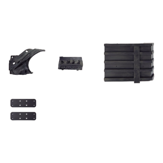
- Page 3 A S S E M B L Y G U I D E KIT 93: THE THORAX AND THE BASE (I) In this kit you will start to assemble the thorax and base. 93-3 93-1 93-2 93-4 93-5 93-6 93-7 PARTS SUPPLIED Name Name...
- Page 4 K I T 9 3 : T H E T H O R A X A N D T H E B A S E ( I ) Place the Thorax parts 93-1 93-2 on the work surface, as shown. 93-1 93-2 93-5...
- Page 5 K I T 9 3 : T H E T H O R A X A N D T H E B A S E ( I ) 93-6 93-6 Fix the Connectors 93-5 in place with four 2.3x6mm screws 93-6. Put the assembly safely aside until it is needed in a later kit.
- Page 6 K I T 9 3 : T H E T H O R A X A N D T H E B A S E ( I ) 93-7 93-7 93-4 In a similar way, fit the other Base Connector 93-4 onto the raised sockets along the...
- Page 7 A S S E M B L Y G U I D E KIT 94: THE THORAX AND THE BASE (II) In this kit you will continue the assembly of the thorax and base. 94-1 94-3 94-2 94-4 94-5 94-7 94-6 PARTS SUPPLIED Name...
- Page 8 K I T 9 4 : T H E T H O R A X A N D T H E B A S E ( I I ) 94-5 Take Thorax parts 94-1 94-2 94-5 place them side by side, as shown on left.
- Page 9 K I T 9 4 : T H E T H O R A X A N D T H E B A S E ( I I ) 94-7 94-7 93-3 93-4 94-3 Take the base assembly 93-3 from the previous kit along with Base 94-3.
- Page 10 K I T 9 4 : T H E T H O R A X A N D T H E B A S E ( I I ) 94-7 94-7 93-4 94-4 94-3 Take one of the Base Connectors 94-4 and fit it over the raised sockets along the same side as...
- Page 11 K I T 9 4 : T H E T H O R A X A N D T H E B A S E ( I I ) 94-7 94-7 94-4 The remaining Connector 94-4 is fitted over the raised sockets along the 94-3 free side of the base,...
- Page 12 A S S E M B L Y G U I D E KIT 95: THE THORAX AND THE BASE (III) In this kit you will continue the assembly of the thorax and base. 95-1 95-2 95-3 95-4 95-5 95-6 95-7 95-8 PARTS SUPPLIED...
- Page 13 K I T 9 5 : T H E T H O R A X A N D T H E B A S E ( I I I ) 95-8 Take the base assembly from the previous kit and fit the four free holes of connector 94-4 over...
- Page 14 K I T 9 5 : T H E T H O R A X A N D T H E B A S E ( I I I ) 42-1 Take the rib cage which was temporarily joined in Pack 6 - 42-2 kit 42 and separate the left and right rib assemblies from the...
- Page 15 K I T 9 5 : T H E T H O R A X A N D T H E B A S E ( I I I ) 95-4 94-1 Test-fit the two pegs on the Right Shoulder Cartilage 95-4 into the raised sockets on the thorax 94-1, as shown...
- Page 16 K I T 9 5 : T H E T H O R A X A N D T H E B A S E ( I I I ) 95-1 Take the Inner Thorax 95-1 and fit the two raised screw sockets into the corresponding holes in the thorax...
- Page 17 K I T 9 5 : T H E T H O R A X A N D T H E B A S E ( I I I ) 95-3 In a similar way to step 4, insert the Left Shoulder Cartilage 95-3 into the...
- Page 18 K I T 9 5 : T H E T H O R A X A N D T H E B A S E ( I I I ) 95-2 95-7 32-3 9Terminez de fixer l’ensemble du pied en insérant deux vis 72-9 dans le pied gauche 2 72-4.
- Page 19 A S S E M B L Y G U I D E K I T 9 6 : T H E T H O R A X In this kit you will continue to work on the Xenomorph’s thorax. 96-1 96-2 96-3...
- Page 20 K I T 9 6 : T H E T H O R A X 96-5 Align the Shoulder parts 96-3 96-4 and fit 96-5 two Connectors 96-5 over the raised screw sockets, as shown. 96-3 96-4 96-6 96-6 42-2 96-5 94-2 93-2...
- Page 21 K I T 9 6 : T H E T H O R A X 42-1 42-2 While holding the assembly together, fit the rib support 42-1 over rib support 42-2. There are three raised sockets on the parts which engage together. 96-6 96-6 96-5...
- Page 22 K I T 9 6 : T H E T H O R A X 96-6 96-5 96-6 96-5 In a similar way, fit the remaining Connectors 96-5 over the remaining two pairs of raised screw sockets and secure in place with four 2.3x6mm screws 96-6.
- Page 23 K I T 9 6 : T H E T H O R A X 96-2 Take Thorax Armature 96-2 and note how one side is smooth and the other cross- hatched. After making sure that the Thorax Armature 96-2 correctly orientated, test-fit in place by sliding it into the...
- Page 24 A S S E M B L Y G U I D E KIT 97: THE THORAX AND THE LIMBS In this kit, you will continue to work on the thorax, to which you will also attach the limbs. 97-1 97-2 97-3 97-4...
- Page 25 K I T 9 7 : T H E T H O R A X A N D T H E L I M B S 97-10 97-10 96-4 97-1 96-3 Take the shoulder assembly 96-3/96-4 from the previous kit. Refer to the inset detail and fit the three recesses on the side of the Back (Battery Compartment) 97-1...
- Page 26 K I T 9 7 : T H E T H O R A X A N D T H E L I M B S 96-4 96-3 97-1 89-1 Take the dorsal appendage assembly from Pack 12 - kit 89 and place the assembly from the previous step on top of it so that the that two parts align, as shown.
- Page 27 K I T 9 7 : T H E T H O R A X A N D T H E L I M B S 97-9 97-8 97-9 97-8 Magnets are now fixed to the assembly. Two thinner magnets 97-8 (blue lines and circles) are fitted into circular...
- Page 28 K I T 9 7 : T H E T H O R A X A N D T H E L I M B S 96-4 Separate the two assemblies and keep the dorsal assembly from Pack 12 - kit 89 to one side until it is needed in a later kit.
- Page 29 K I T 9 7 : T H E T H O R A X A N D T H E L I M B S 97-4 Fit the two pegs of the Cartilage (Right Shoulder) 97-4 into the matching raised sockets on the back of shoulder 96-3.
- Page 30 K I T 9 7 : T H E T H O R A X A N D T H E L I M B S RIGHT ARM 51-2 97-7 Take the right arm assembly from Pack 7 - kit 51 and fit one of the Sleeves 97-7 around the narrow part of the humerus joint 51-2, as shown on left.
- Page 31 K I T 9 7 : T H E T H O R A X A N D T H E L I M B S 51-2 60-1 RIGHT ARM LEFT ARM Carefully fit the left humerus joint 60-1 into the semi- circular recess in the back of shoulder 96-4, as shown.
- Page 32 K I T 9 7 : T H E T H O R A X A N D T H E L I M B S Take the thorax armature plate 96-1 96-1 from the previous kit. After carefully studying how the part is orientated so that the smooth side is facing outwards, test-fit the part onto...
- Page 33 K I T 9 7 : T H E T H O R A X A N D T H E L I M B S 97-11 The two sub-assemblies are secured together using two 2.6x16mm screws 97-11. These are inserted into the holes in the joint 80-5.
- Page 34 A S S E M B L Y G U I D E KIT 98: THE NECK (II) In this kit you will continue to work on the Xenomorph’s neck. 98-3 98-1 98-2 98-4 98-6 98-5 98-7 98-11 98-10 98-8 98-9 PARTS SUPPLIED Name...
- Page 35 K I T 9 8 : T H E N E C K ( I I ) 11-4 11-5 Take the skull assembly which was last worked upon in Pack 7 - kit 46, and remove the pin 11-5 from the rod 11-4.
- Page 36 K I T 9 8 : T H E N E C K ( I I ) 11-4 Once certain that the notch is in the correct position, pass the neck part 97-3 and two Bearings 98-2 over the rod 11-4.
- Page 37 K I T 9 8 : T H E N E C K ( I I ) 98-2 11-4 11-5 Put aside the pin 11-5 replace it with Pin 98-11 which is supplied with this kit. Insert it into the original hole in rod 11-4. The pin should sit between the two Bearings 98-2, point towards the front of the head and be fully...
- Page 38 K I T 9 8 : T H E N E C K ( I I ) 98-1 98-10 97-2 97-3 98-10 Turn the head assembly over and while holding the parts in place, fit the necks 97-2 98-1 onto the raised screw sockets on either side of the neck 97-3.
- Page 39 K I T 9 8 : T H E N E C K ( I I ) 98-7 EXPERT ADVICE The connection of the cable to the motor assembly 98-6 is very delicate. Therefore, try to avoid unnecessa- ry movement of it when handling the assembly.
- Page 40 K I T 9 8 : T H E N E C K ( I I ) 98-5 Once certain that the Motor Assembly 98-6 is in the correct 98-6 position, push-fit Connector 98-5 on to the spindle. There is a ridge on the underside of Connector 98-5 which fits into the slot in the...
- Page 41 K I T 9 8 : T H E N E C K ( I I ) 98-10 98-10 When sure of the correct fit, secure the Motor Assembly 98-6 in place with four 2.3x6mm screws 98-10. 98-6 Fit the Microphone 98-8 by gently pushing it into the Microphone Tube 98-9.
- Page 42 K I T 9 8 : T H E N E C K ( I I ) 98-3 98-8 98-9 Insert the cable of Microphone 98-8 through the hole in Neck 98-3 so that the Microphone Tube 98-9 fits neatly in the hole in Neck 98-3, as shown in the inset above.
- Page 43 K I T 9 8 : T H E N E C K ( I I ) KIT 98 IS COMPLETE The motor and associated parts for the neck movement have been fitted along with the neck microphone.
- Page 44 A S S E M B L Y G U I D E KIT 99: THE REMOTE CONTROL, THE BATTERY AND THE SKULL In this kit you well assemble the remote control and the battery plus attach the skull to the rest of the Xenomorph’s body. 99-4 99-5 99-10...
- Page 45 A S S E M B L Y G U I D E THE REMOTE CONTROL, THE BATTERY AND THE SKULL PARTS SUPPLIED Name Name 99-1 Front panel - remote control 99-14 Main PCB 99-2 Rear panel - remote control 99-15 Switch 99-3 Battery cover - remote control...
- Page 46 K I T 9 9 : T H E R E M O T E C O N T R O L , T H E B AT T E RY A N D T H E S K U L L 99-4 99-7 99-5...
- Page 47 K I T 9 9 : T H E R E M O T E C O N T R O L , T H E B AT T E RY A N D T H E S K U L L 99-2 Lay the Rear Panel 99-2...
- Page 48 K I T 9 9 : T H E R E M O T E C O N T R O L , T H E B AT T E RY A N D T H E S K U L L 99-2 Two AAA batteries (not supplied) are inserted into...
- Page 49 K I T 9 9 : T H E R E M O T E C O N T R O L , T H E B AT T E RY A N D T H E S K U L L 99-17 In a similar way to the 99-17...
- Page 50 K I T 9 9 : T H E R E M O T E C O N T R O L , T H E B AT T E RY A N D T H E S K U L L 99-18 Open the battery compartment...
- Page 51 K I T 9 9 : T H E R E M O T E C O N T R O L , T H E B AT T E RY A N D T H E S K U L L Locate the two red and black cables coming from the head assembly and insert the shorter one (which...
- Page 52 K I T 9 9 : T H E R E M O T E C O N T R O L , T H E B AT T E RY A N D T H E S K U L L Take great care with the next steps where the head is fitted.
- Page 53 K I T 9 9 : T H E R E M O T E C O N T R O L , T H E B AT T E RY A N D T H E S K U L L Connect each of the extension cables in turn to the corresponding cable on...
- Page 54 K I T 9 9 : T H E R E M O T E C O N T R O L , T H E B AT T E RY A N D T H E S K U L L 99-5 99-4 99-7...
- Page 55 K I T 9 9 : T H E R E M O T E C O N T R O L , T H E B AT T E RY A N D T H E S K U L L Once certain the electronic functions are working, the head can be fitted.
- Page 56 K I T 9 9 : T H E R E M O T E C O N T R O L , T H E B AT T E RY A N D T H E S K U L L 91-2 91-3 Again, keeping the head...
- Page 57 K I T 9 9 : T H E R E M O T E C O N T R O L , T H E B AT T E RY A N D T H E S K U L L KIT 99 IS COMPLETE The remote control has been constructed, the main PCB fitted, the head cables...
- Page 58 A S S E M B L Y G U I D E KIT 100: THE SKULL, THE BASE AND POSING THE MODEL In this kit you will finish the project, completing the assembly of the skull and the base, before installing the Xenomorph model onto the base. 100-1 100-2 100-3...
- Page 59 K I T 1 0 0 : T H E S K U L L , T H E B A S E A N D P O S I N G T H E M O D E L 100-12 100-12 100-12...
- Page 60 K I T 1 0 0 : T H E S K U L L , T H E B A S E A N D P O S I N G T H E M O D E L 100-12 100-12 100-12...
- Page 61 K I T 1 0 0 : T H E S K U L L , T H E B A S E A N D P O S I N G T H E M O D E L To strengthen the base and make it more stable, 100-14...
- Page 62 K I T 1 0 0 : T H E S K U L L , T H E B A S E A N D P O S I N G T H E M O D E L 100-5 100-14 The three brackets...
- Page 63 K I T 1 0 0 : T H E S K U L L , T H E B A S E A N D P O S I N G T H E M O D E L The final brackets 100-17 100-17...
- Page 64 K I T 1 0 0 : T H E S K U L L , T H E B A S E A N D P O S I N G T H E M O D E L Insert the notched end of the Tail Support pole 100-11...
- Page 65 K I T 1 0 0 : T H E S K U L L , T H E B A S E A N D P O S I N G T H E M O D E L Take the dorsal growth assembly 89-2/90- 2, that you assembled in Pack 12 - kit 90, and...
- Page 66 K I T 1 0 0 : T H E S K U L L , T H E B A S E A N D P O S I N G T H E M O D E L 79-4 78-1 When certain that the Xenomorph will...
- Page 67 K I T 1 0 0 : T H E S K U L L , T H E B A S E A N D P O S I N G T H E M O D E L Place the base plinth on the floor making sure that the surface is flat and the base is stable.
- Page 68 K I T 1 0 0 : T H E S K U L L , T H E B A S E A N D P O S I N G T H E M O D E L 100-1 Complete the build by fitting the Upper Membrane...
Need help?
Do you have a question about the ALIEN PACK 13 and is the answer not in the manual?
Questions and answers