
Subscribe to Our Youtube Channel
Related Manuals for Hachette ALIEN PACK 12


Summary of Contents for Hachette ALIEN PACK 12
- Page 1 A L I E N spectacular scale EASY EASY ASSEMBLY ASSEMBLY BUILD THE TERRIFYING XENOMORPH FROM ALIEN PACK 12 KITS 85 - 92...
- Page 2 Keep away from children. If you suspect a magnet has been swallowed, seek medical help straight away. Hachette Partworks Ltd, 4th Floor, Jordan House, Some parts may have sharp edges, please handle them with care.
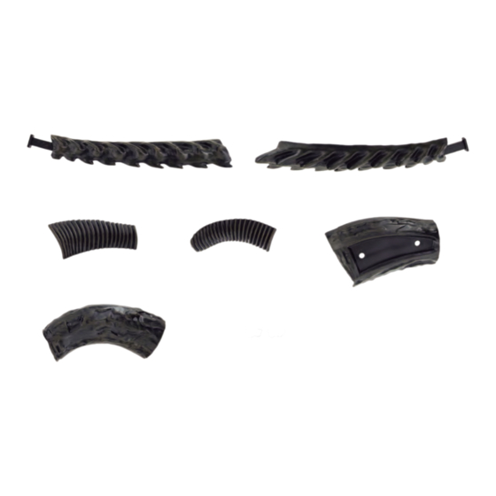
- Page 3 A S S E M B L Y G U I D E KIT 85: THE TAIL AND THE DORSAL GROWTHS (IV) In this kit you will continue to work on the tail and dorsal appendages. 85-1 85-2 85-5 85-3 85-4 85-6 85-7...
- Page 4 K I T 8 5 : T H E T A I L A N D T H E D O R S A L G R O W T H S ( I V ) 85-2 Take the tail assembly 84-2/84- which was worked on in step 1 of pack 11 - kit 84.
- Page 5 K I T 8 5 : T H E T A I L A N D T H E D O R S A L G R O W T H S ( I V ) 85-4 (B7) Similarly, test-fit the two pegs on Back Protector B7 85-4 into the matching holes in...
- Page 6 K I T 8 5 : T H E T A I L A N D T H E D O R S A L G R O W T H S ( I V ) 85-8 85-8 Secure the Connectors 85-7 in place with four 2.3x6mm screws...
- Page 7 A S S E M B L Y G U I D E KIT 86: THE TAIL AND THE DORSAL GROWTHS (V) In this kit you will continue to work on the tail and its dorsal appendages. 86-1 86-2 86-3 86-4 86-5 86-6...
- Page 8 K I T 8 6 : T A I L A N D D O R S A L G R O W T H S ( V ) 86-2 85-2 Take the tail assembly 1/85-2 which was worked on 85-1 in the previous kit and test-fit the Tail...
- Page 9 K I T 8 6 : T A I L A N D D O R S A L G R O W T H S ( V ) 86-6 Next, Back C5 86-5 86-6 and Back C4 86-4 are joined together by fitting two Connectors 86-6...
- Page 10 86-7 86-7 Turn the assembly over and fix together with two 2.3x6mm screws 86-7. 86-4 86-5 KIT 86 IS COMPLETE The tail has been completed and further work has been done to the dorsal growths.
- Page 11 A S S E M B L Y G U I D E KIT 87: THE DORSAL GROWTHS (I) In this kit you will continue to build the dorsal appendages. 87-1 87-2 87-3 87-4 87-5 87-6 87-7 87-8 PARTS SUPPLIED Name Name 87-1...
- Page 12 K I T 8 7 : D O R S A L G R O W T H S ( I ) 87-6 (C7) Take the back assembly 87-5 (C6) 4/86-5 which was worked on in the previous kit and test-fit the two pegs on Back Protector C6 87-5...
- Page 13 K I T 8 7 : D O R S A L G R O W T H S ( I ) 87-7 87-7 87-3 In a similar way to steps 2 and 3, join Back 87-4 87-3 and Back D4 87-4 together by fitting two Connectors...
- Page 14 K I T 8 7 : D O R S A L G R O W T H S ( I ) 87-1 87-2 The assembly 1/87-2, from step 3 and the assembly 87-3/87-4 from the previous step are joined together as shown on the left.
- Page 15 A S S E M B L Y G U I D E KIT 88: THE DORSAL GROWTHS (II) In this kit you will continue to build the dorsal appendages. 88-1 88-2 88-3 88-4 88-5 PARTS SUPPLIED Name Name 88-1 Back Protector D5 88-4 Battery Compartment 1...
- Page 16 K I T 8 8 : D O R S A L G R O W T H S ( I I ) 88-2 (D6) 88-3 (D7) 88-3 87-3 87-3 87-4 87-4 Take the back assembly 87-3/87- from the previous kit and test-fit the two pegs on Back Protector Similarly, test-fit the two pegs on 88-3...
- Page 17 K I T 8 8 : D O R S A L G R O W T H S ( I I ) 88-5 Next, take the Vertebrae 88-5 and the Back Battery Compartment 88-4 place them on the work surface.
- Page 18 A S S E M B L Y G U I D E KIT 89: THE DORSAL GROWTHS (III) In this kit you will continue to build the dorsal appendages. 89-1 89-2 89-3 89-5 89-4 PARTS SUPPLIED Name Name 89-1 Back Battery Compartment 89-4 Magnets...
- Page 19 K I T 8 9 : D O R S A L G R O W T H S ( I I I ) 89-1 89-5 89-5 89-1 88-4 88-4 The Back Battery Compartments 88-4 89-1 are joined Secure the two parts together, as shown above.
- Page 20 K I T 8 9 : D O R S A L G R O W T H S ( I I I ) 82-5 Place the back assembly 84-5 4/89-1 on the work surface and take the assemblies 82-4/82- 82-4 84-4/84-5 which were...
- Page 21 K I T 8 9 : D O R S A L G R O W T H S ( I I I ) 89-5 89-3 89-3 Two Connectors 89-3 are fitted over the raised screw sockets on Back 89-2, as shown, and secured in place with two 2.3x6mm screws 89-5.
- Page 22 A S S E M B L Y G U I D E KIT 90: THE DORSAL GROWTHS (IV) In this kit you will continue to build and add the dorsal appendages. 90-1 90-2 90-3 90-4 90-5 PARTS SUPPLIED Name Name 90-1 Back E2...
- Page 23 K I T 9 0 : T H E D O R S A L G R O W T H S ( I V ) 89-2 89-3 90-1 89-3 Take the back assembly 89-2 from the last kit and join it to Back 90-1 using the two previously fitted Connectors 89-3.
- Page 24 K I T 9 0 : T H E D O R S A L G R O W T H S ( I V ) 90-4 In a similar way, join Back E3 90-2 to Back 90-3 using two 90-4 Connectors 90-4.
- Page 25 K I T 9 0 : T H E D O R S A L G R O W T H S ( I V ) Take the back assemblies 2/90-1 90-2/90-3 and test-fit them together, as shown. There are twelve raised sockets on each that fit together.
- Page 26 A S S E M B L Y G U I D E KIT 91: THE RIGHT SHOULDER GROWTH In this kit you will work on the growth to be attached to the right shoulder. 91-1 91-2 91-3 91-4 91-5 91-6 PARTS SUPPLIED Name...
- Page 27 K I T 9 1 : T H E R I G H T S H O U L D E R G R O W T H Fix the Connectors 91-5 in place with four 2.3x6mm screws 91-6. 91-5 91-6 91-5 91-6...
- Page 28 K I T 9 1 : T H E R I G H T S H O U L D E R G R O W T H 91-1 91-2 Take the assembly 91-1/91-2 from step 2 and test-fit it, as shown, to assembly 91-3/91-4.
- Page 29 A S S E M B L Y G U I D E KIT 92: THE LEFT SHOULDER GROWTH In this kit you will work on the growth to be attached to the left shoulder. 92-1 92-2 92-3 92-4 92-5 92-6 PARTS SUPPLIED Name...
- Page 30 K I T 9 2 : T H E L E F T S H O U L D E R G R O W T H 92-5 92-5 92-1 Take the Shoulder Appendages 92-1 92-2 92-2 and join them together by fitting two Connectors 92-5 over the...
- Page 31 K I T 9 2 : T H E L E F T S H O U L D E R G R O W T H In a similar way, 92-5 Shoulder Appendages 92-3 92-4 joined by fitting two Connectors 92-5 over the raised screw...
- Page 32 K I T 9 2 : T H E L E F T S H O U L D E R G R O W T H 92-2 92-1 The two assemblies 92-1/92-2 92-3/92-4 test-fitted together, as indicated by the red lines. After noting the contact areas, glue the two assemblies firmly...
Need help?
Do you have a question about the ALIEN PACK 12 and is the answer not in the manual?
Questions and answers