Advertisement
Quick Links
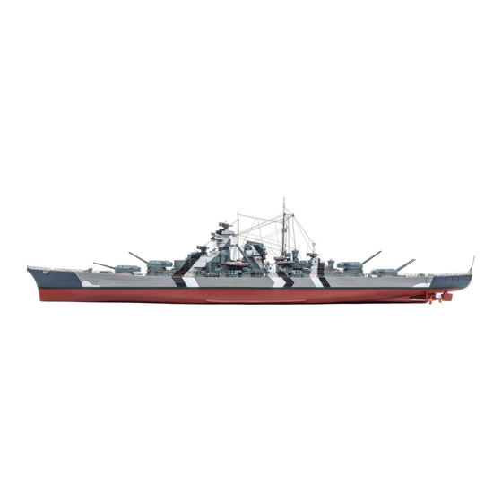
Pack 07 | Build Instructions
Your 1:200 scale model of the legendary battleship Bismarck is packed with
intricate details which precisely replicate every aspect of this state-of-the-
art warship. Each piece has been created using premium quality materials to
bring maximum enjoyment during your complete build.
In your seventh model pack, you will assemble:
STAGE 69: MOTOR FOR THE THIRD 15CM GUN
STAGE 75: DETAILS FOR THE UPPER DECK
STAGE 70: THE FOURTH 15CM GUN TURRET
STAGE 76: ROPE REELS AND FUNNEL DETAILS
STAGE 71: THE NEXT KEEL SECTION
STAGE 77: HULL SECTION AND FUNNEL
DETAILS
STAGE 72: MOTOR FOR THE FOURTH
15CM GUN
STAGE 78: FINAL DETAILS FOR THE FUNNEL
STAGE 73: GEAR ASSEMBLY FOR THE SECOND
STAGE 79: THE NEXT HULL SECTION
38CM GUN
STAGE 80: THE TWO AIRCRAFT HANGARS
STAGE 74: ELEVATION MOTOR FOR THE
SECOND 38CM GUN TURRET
© 2020 Hachette Partworks Ltd.
North America Edition by Agora Models
Advertisement

Subscribe to Our Youtube Channel
Related Manuals for Hachette AGORA BISMARCK THE LEGENDARY BATTLESHIP


Summary of Contents for Hachette AGORA BISMARCK THE LEGENDARY BATTLESHIP
- Page 1 STAGE 73: GEAR ASSEMBLY FOR THE SECOND STAGE 79: THE NEXT HULL SECTION 38CM GUN STAGE 80: THE TWO AIRCRAFT HANGARS STAGE 74: ELEVATION MOTOR FOR THE SECOND 38CM GUN TURRET © 2020 Hachette Partworks Ltd. North America Edition by Agora Models...
- Page 2 Advice from the experts Spare screws are included with each part. Occasionally, you may be instructed to keep spare or unused screws for a later stage. Keep these spares in a safe place and label them correctly. Please make sure you don’t mix up the screws. They look quite similar, but the threads do vary slightly.
-
Page 3: Components Checklist
STAGE 69 MOTOR FOR THE THIRD 15cm GUN 69-02 69-01 69-03 69-05 69-04 COMPONENTS CHECKLIST 69-01: 69-04: Motor Cable label 69-02: 69-05: Cable for the gun motor 69-03: Motor housing Three 2 x 5mm PB screws . PREPARING THE MOTOR 69-05 69-05 69-04... - Page 4 Fit the connector on the unlabelled 69-05 end of cable into the socket in 69-01 the circuit board on the motor 69-05 69-01 69-02 Fit the cog over the shaft of the 69-01 motor , as shown. 69-02 69-01 . FITTING THE MOTOR TO THE UPPER DECK Take the upper deck structure 19-01 22-01...
- Page 5 69-03 Fit the motor housing over 69-01 the motor . The two screw holes 69-03 on the side of the cover should align with the screw sockets on the underside of the upper deck. 69-01 Whilst supporting the deck from below, fix the motor housing in place with two screws.
- Page 6 STAGE 70 THE FOURTH 15cm GUN TURRET 70-02 70-03 70-01 70-04 70-05 70-08 70-06 70-07 1.7 x 6 2 x 5 COMPONENTS CHECKLIST 70-01: 15cm gun housing 70-04: 70-08: Cable label (SBII – second starboard turret) 70-05: Left rangefinder hood Two 2 x 5mm PB screws 70-02: Gun turret base plate...
- Page 7 70-01 70-05 70-06 70-03 70-01 70-06 70-03 Fix the right rangefinder hood to the right- Fit the gun barrels through the holes in the 70-01 hand side of the gun turret housing in the same way. front of the gun turret and position the cradle so that the two tabs fit into recesses in the gun turret (see arrows).
- Page 8 . FITTING THE SWITCH 70-08 Wrap the cable label around the 70-07 switch cable near the connector. Fit the switch on the other end of the 70-07 70-07 cable into the recess near the gun turret, on the underside of deck 48-01 70-08 section...
- Page 9 STAGE 71 THE NEXT KEEL SECTION 71-02 71-01 COMPONENTS CHECKLIST 71-01: Keel section PM: Five 2 x 4mm PM screws 71-02: Connector FITTING THE KEEL SECTION Take the hull assembly from stage 68. 71-02 Fit the sockets on the connector over the raised screw sockets on the 56-01 56-01...
- Page 10 71-02 Fix the connector in place with two screws. 56-01 71-02 71-01 Fit the next keel section under the 71-02 connector so that the screw sockets fit in place. Fix in place with two 71-01 screws. 71-02 Completed work The next keel section has been fitted to the hull assembly.
- Page 11 STAGE 72 MOTOR FOR THE FOURTH 15cm GUN 72-01 72-03 72-02 COMPONENTS CHECKLIST 72-01: Motor 72-03: Cable label 72-02: PB: Three 2 x 5mm PB screws Cable for the motor PREPARING THE MOTOR 72-02 Take the cable and the cable 72-03 label .
- Page 12 Remove the backing from the cable 72-03 label and wrap it around one end 72-02 of the cable near the connector as shown. 72-02 72-03 Plug the connector on the other end of 72-02 the cable into the circuit board on 72-01 the motor as shown.
- Page 13 STAGE 73 GEAR ASSEMBLY FOR THE SECOND 38cm GUN 73-02 73-01 73-03 73-04 73-06 73-07 73-08 73-05 2 x 4 73-10 73-09 73-11 2 x 6 COMPONENTS CHECKLIST 73-01: 73-04: Right support 73-08: Gear arm Six 2 x 6mm PB bracket (R) screws 73-02:...
- Page 14 73-02 73-02 72-01 73-02 72-01 Fit the motor housing over the motor Fix the motor housing in place using two 2 x 5mm as shown. screws, supplied with stage 72. . GEAR ASSEMBLY FOR THE ELEVATION OF THE SECOND 38cm GUN TURRET 73-06 73-07 73-10...
- Page 15 73-11 73-11 73-10 73-06 73-08 73-05 73-05 73-11 73-06 Position the peg on cog on the left-hand side Fit the shaft into the hole in cog of the assembly as shown (arrow). Fit the slot in the 73-08 gear arm over the peg, taking care to position it in the correct orientation.
- Page 16 73-03 2 x 4 73-09 53-07 Turn the gear assembly over and fix the left support Take the deck assembly from step 4. Identify the cog 73-03 73-09 53-07 bracket in place on the gear housing on the underside of the deck, beneath the with a 2 x 4mm screw, as shown.
- Page 17 STAGE 74 ELEVATION MOTOR FOR THE SECOND 38cm GUN TURRET 74-01 74-02 COMPONENTS CHECKLIST 74-01: Motor Three 1.7 x 6mm PB screws 74-02: Cable label FITTING THE MOTOR 74-01 Take the motor with its cable. 74-02 Remove the cable label from its backing and fit it around the end of the cable near the connector.
- Page 18 Take the deck assembly from the previous stage with the gear housing for 73-06 the second 38cm gun turret. Make sure the deck is fully supported, to avoid damage to any of the parts. Identify the 73-06 in the gear housing assembly. 74-01 Fit the shaft of the motor into the...
- Page 19 STAGE 75 DETAILS FOR THE UPPER DECK 75-04 75-01 75-02 75-03 COMPONENTS CHECKLIST 75-01: Port lower hull section 75-03: Four bollards Four 2 x 4mm PM screws 75-02: Deck details (A– D) 75-04: Two roller fairleads . FITTING THE NEXT HULL SECTION 75-01 75-01 71-01...
- Page 20 . DETAILS FOR THE UPPER DECK AND FORWARD BARBETTE 75-03 75-03 10-01 10-01 Take the upper deck assembly from stage 18. Position it On the opposite side of the deck assembly identify 75-03 carefully on your work surface, supporting it so that the the fixing point for the second pair of bollards gear housing and other details on the underside are not Check the fit and glue in place, using a little superglue.
- Page 21 10-02 10-01 Check the instructions for turning the forward 38cm To the aft of the forward 38cm gun, fit the second and gun in stage 18. To stop the gun in the desired third hatches , gluing in place in slight recesses in position, turn off the power using the switch on the the deck, as shown.
- Page 22 STAGE 76 ROPE REELS AND FUNNEL DETAILS 76-02 76-04 76-03 76-01 76-06 76-07 76-05 76-08 76-10 76-11 76-09 76-12 76-13 COMPONENTS CHECKLIST 76-01: Large rope reels (A1, A2) 76-06: Crane details (C1–C4) 76-10: Companionway components (D1–D3) 76-02: Small rope reels (B1, B2) 76-07: Port hull support (L) 76-11:...
- Page 23 76-01 76-01 76-13 76-13 76-13 Take the rope and use a drop of superglue to When you have two or three even layers of rope in stick the end of the rope to the drum of the rope reel place cut the rope and fix the end in place with a little 76-01 .
- Page 24 19-01 76-02 19-01 76-02 76-02 76-02 The first small rope reel is fitted at the front of The second small rope reel is glued to the 19-01 19-01 the upper deck , on the port side of the turret upper deck section , close to the first rope reel.
- Page 25 76-05 It is important to bend supports the correct way. Study this photograph and the next step very Repeat the previous step to assemble the starboard carefully, noting the position of the tabs (arrows). Cut 76-05 76-10 crane, using the second boom , trolley the supports from frame...
- Page 26 76-05 76-05 76-03 76-05 63-05 76-05 This view of the underside of the searchlight platform When you are happy with the fit, glue the tab on the 63-05 76-03 76-05 shows the pins at the top of the crane booms platform in place.
- Page 27 . SEARCHLIGHT HOODS AND LADDERS 65-03 65-03 76-04 76-04 76-04 76-04 Take one of the searchlight hoods . The hood has The hood pivots on the hinge points. A small two holes at the hinge points (arrow), which fit over pegs notch on the top (blue arrow) fits over a raised tab 65-03 65-03...
- Page 28 Check the fit of one set of ladders Similarly, take the second set of ladders the port side of the funnel, positioning them as and fit on the starboard side of the funnel. When you shown, with the pegs located in corresponding holes are happy with the fit, glue the pegs in place.
- Page 29 STAGE 77 HULL SECTION AND FUNNEL DETAILS 77-01 77-02 COMPONENTS CHECKLIST 77-01: Lower starboard 77-02: Railings and supports Four PM 2 x 4mm screws hull section (A–E) . FITTING THE HULL SECTION 77-01 77-01 60-01 71-01 77-01 Check the fit of the next starboard hull section Fix in place with three 2 x 4mm screws.
- Page 30 . FITTING THE RAILINGS 76-03 77-02 Cut railing from the frame . Take the funnel When you are happy with the fit, glue the pegs assembly from stage 76 and check the fit of the at the bottom of the railing in place on the crane 76-03 railing across the rear of the funnel.
- Page 31 65-04 77-02 Cut railing from frame and bend the two The railing fits at the rear of the funnel assembly: ends at right angles, as shown. four pegs on the railing fit into holes in the funnel 65-04 extension . When you are happy with the fit, glue in place.
- Page 32 STAGE 78 FINAL DETAILS FOR THE FUNNEL A2 A3 78-03 78-01 78-02 78-04 78-05 78-06 78-09 78-08 78-07 COMPONENTS CHECKLIST 78-01: 78-05: 78-09: Foremast base Searchlight bracket (x2) Ladder, mast top and supports (D1 – D3) 78-02: Lockers and steam 78-06: Railings and mast details whistle (A1 –...
- Page 33 78-02 78-02 Cut two lockers from frame . These fit on Cut the steam whistle from frame . Check the searchlight platform behind the funnel, as shown. the fit at the rear of the funnel: a peg on the base of Glue in place.
- Page 34 78-05 78-04 78-05 Cut the two supports from the frame Take a searchlight bracket and a support note how the sides are bent the opposite way to from step 1. Check the fit across the inside of the 78-05 supports .
- Page 35 65-01 65-01 78-05 78-05 78-05 78-05 Check the fit of the first bracket on the starboard The second searchlight bracket is glued to the side of the funnel, beneath the searchlight platform port side of the funnel beneath the searchlight 65-01 65-01 .
- Page 36 78-06 78-06 The railing from frame has to be bent to fit The railing from frame has to be bent to fit around the curve at the edge of the foremast base around the curve on the other side of the foremast 78-01 78-01 (see also step 7, below).
- Page 37 78-03 78-06 78-09 Cut part from frame . Bend it to shape as you Cut the ladder from frame . Identify the fit it in place: the loop in part fits over the top of the seven pairs of pegs down the sides of the ladder 78-03 mast , then the arms are bent down to the sides,...
- Page 38 78-01 78-01 Cut the first of the two long struts from frame The second long strut fits in the same way 78-09 78-01 . The small peg at the base fits into a hole in from the foremast base to the rear of the 78-01 the foremast base ;...
- Page 39 STAGE 79 THE NEXT HULL SECTION 79-01 79-02 COMPONENTS CHECKLIST 79-01: Upper starboard hull 79-02: Connector Five 2 x 4mm screws section FITTING THE HULL SECTION Take the hull assembly from stage 77. 79-01 Check the fit of hull section ;...
- Page 40 79-01 Fix hull section in place with two screws. 79-01 77-01 79-02 Fit the connector over the join 68-01 79-01 between hull sections 68-01 so that the sockets in the connector fit 79-01 over the raised screw sockets on the hull sections.
- Page 41 STAGE 80 THE TWO AIRCRAFT HANGARS 80-01 80-02 80-03 80-04 80-05 80-06 80-07 COMPONENTS CHECKLIST NOTE: The cradle parts on 80-01: Port hangar 80-05: Details for the starboard frame 80-06 are all very hangar (L–R) 80-02: Starboard hangar similar. Take some time to 80-06: Boat cradles (roofs of identify the three different...
- Page 42 80-01 80-01 Take the large vent and smaller part from the The door and column fit next to part on the 80-03 80-01 frame . Check the fit and glue in place as shown. outer wall of the hangar . Glue in place. 80-01 80-01 The vent...
- Page 43 80-02 80-02 80-05 The door, part from frame is fitted on the The two roof vents are fitted on either side of outside of part . The vent is fitted near the forward the roof, as shown. Glue them in place. 80-02 end of the hangar .
- Page 44 80-02 80-02 Repeat the steps to fit the boat cradles on the Fix boat cradles to the outer wall of the right 80-02 80-02 starboard hangar : glue the rectangular peg on hangar as shown. cradle into the hole at the top of the hangar, near the door 80-01 80-01...
- Page 45 . SUPPORT STRUTS FOR THE BOAT CRADLES 80-01 80-01 80-07 80-07 Cut a strut from frame . Fit it across the three Cut three triangular frames from frame 80-01 side cradles on the port hangar and glue in and fix to the outer edge of the three cradles on the 80-01 place as shown.
Need help?
Do you have a question about the AGORA BISMARCK THE LEGENDARY BATTLESHIP and is the answer not in the manual?
Questions and answers