Table of Contents
Advertisement
Quick Links
SERVICE MANUAL
LN-9282-14
June - 2014
MODEL: A13657
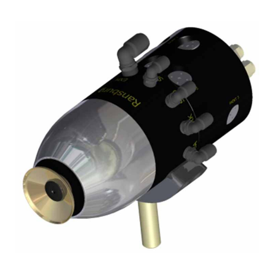
AEROBELL 268
IMPORTANT:
IMPORTANT:
carefully read SAFETY PRECAUTIONS, starting
carefully read SAFETY PRECAUTIONS, starting
on page 1, and all instructions in this manual.
on page 1, and all instructions in this manual.
Keep this Service Manual for future reference.
Keep this Service Manual for future reference.
Service Manual Price:
TM
Before using this equipment,
Before using this equipment,
Service Manual Price:
$50.00 (U.S.)
Ransburg
$50.00 (U.S.)
Advertisement
Table of Contents

Summary of Contents for Ransburg AEROBELL 268 A13657
- Page 1 SERVICE MANUAL Ransburg LN-9282-14 June - 2014 AEROBELL 268 MODEL: A13657 IMPORTANT: IMPORTANT: Before using this equipment, Before using this equipment, carefully read SAFETY PRECAUTIONS, starting carefully read SAFETY PRECAUTIONS, starting on page 1, and all instructions in this manual.
-
Page 2: Table Of Contents
Ransburg Aerobell 268 - Contents CONTENTS PAGE SAFETY: SAFETY PRECAUTIONS ......................1 HAZARDS / SAFEGUARDS ....................2-5 ATEX: 6-12 EUROPEAN ATEX DIRECTIVE ....................6 LABELS ..........................7 CONFIGURATION DRAWINGS .....................8-12 INTRODUCTION: 13-21 GENERAL DESCRIPTION ....................13 FEATURES ..........................13 OPERATING CHARACTERISTICS AND SPECIFICATIONS ..........14-17 DIMENSIONAL CHARACTERISTICS ..................18 IMPORTANT NUMBERS ......................19... - Page 3 Ransburg Aerobell 268 - Contents CONTENTS (Cont.) PAGE MAINTENANCE: 37-68 O-RINGS ..........................38-39 PREVENTIVE MAINTENANCE .....................39-41 AIR FILTERS / ELEMENT REPLACEMENT .................41 BELL CUP CLEANINGS ......................42 CLEANING SHAPING AIR HOLES ..................43 AEROBELL 268 PREVENTIVE MAINTENANCE SCHEDULE ..........44 TOOLS REQUIRED TO DISASSEMBLE AEROBELL ............45 OPTIONAL TOOLS REQUIRED TO DISASSEMBLE AEROBELL ........46...
-
Page 4: Safety
If you do not have the manuals and safety literature for your Ransburg system, contact your local Ransburg representative or Ransburg. LN-9282-14... -
Page 5: Hazards / Safeguards
Aerobell 268 - Safety HAZARD SAFEGUARDS AREA Tells what the hazard is. Tells how to avoid the hazard. Tells where hazards may occur. Spray Area Fire Hazard Fire extinguishing equipment must be present Improper or inadequate in the spray area and tested periodically. operation and maintenance procedures Spray areas must be kept clean to prevent the... - Page 6 Aerobell 268 - Safety AREA HAZARD SAFEGUARDS Tells where hazards Tells what the hazard is. Tells how to avoid the hazard. may occur. Explosion Hazard Spray Area Electrostatic arcing must be prevented. Safe Improper or inadequate sparking distance must be maintained between operation and maintenance the parts being coated and the applicator.
- Page 7 Aerobell 268 - Safety AREA HAZARD SAFEGUARDS Tells where hazards Tells what the hazard is. Tells how to avoid the hazard. may occur. Spray Area / Electrical Discharge High Voltage Parts being sprayed and operators in the spray There is a high voltage device Equipment area must be properly grounded.
- Page 8 Aerobell 268 - Safety AREA HAZARD SAFEGUARDS Tells where hazards Tells what the hazard is. Tells how to avoid the hazard. may occur. Electrical Electrical Discharge Equipment Unless specifically approved for use in High voltage equipment is hazardous locations, the power supply, control utilized in the process.
-
Page 9: Atex
Aerobell 268 - Atex/FM EUROPEAN ATEX DIRECTIVE 94/9/EC, ANNEX II, 1.0.6 The following instructions apply to equipment 8. The certification of this equipment relies upon covered by certificate number Sira 13ATEX5176X: the following materials used in its construction: 1. The equipment may be used with flammable If the equipment is likely to come into contact with gases and vapors with apparatus groups II and aggressive substances, then it is the responsibility... -
Page 10: Labels
Aerobell 268 - Atex/FM AB268 A13657 ATEX PRODUCT • If an object is within the 204mm safe distance, it must MARKING DEFINITIONS be cleared prior to restarting and/or re-energizing the system. Ex Certificate Number: Sira 13ATEX5176X • The materials used in the construction of this equip- Sira = Notified Body performing EC-type examination ment contain levels of Al, Mg, Ti and Zi that are greater 13 = Year of certification... -
Page 11: Configuration Drawings
Aerobell 268 - Atex/FM CONFIGURATION DRAWING A13708 ORDERING INSTRUCTIONS: A13657 XX-XX-XX-X-X-X-X-X AS INDICATED IN TABLES A-J TABLE H (SPINDLE ASSEMBLY) TABLE G (HIGH VOLTAGE CABLE) TABLE F (POWER SUPPLY) TABLE E (TOOL KIT) TABLE D (VALVE MANIFOLD ASSEMBLY) TABLE C (SHAPE AIR KIT) TABLE B (BELL CUP ASSEMBLY) TABLE A (FLUID TIP) BASIC PART NUMBER... - Page 12 Aerobell 268 - Atex/FM TABLE B - BELL CUP ASSEMBLY Bell Cup Splash Plate Dash # Part # Description Only (Ref.) Only (Ref.) A12942-02 65MM ALUMINUM, PLATED A12782-00 A13644-00 A13676-00 65MM TITANIUM A13675-00 A13644-00 A12833-01 30MM ALUMINUM, PLATED A12832-00 A13274-00 A12833-03 30MM TITANIUM A13531-00...
- Page 13 Aerobell 268 - Atex/FM TABLE D - VALVE MANIFOLD ASSEMBLY Dash # Part # Description A13691-00 8 VALVES (3 PAINT, 3 DUMP, 1 SOLVENT, 1 AIR) A13691-01 6 VALVES (PAINT #1 AND #2, DUMP #1 AND #2, AIR, SOLVENT) A13691-02 4 VALVES (PAINT #1, DUMP #1, AIR, SOLVENT) TABLE E - TOOL KITS Dash #...
- Page 14 Aerobell 268 - Atex/FM TABLE F - POWER SUPPLY Dash # Description Part # Qty. "N" NO POWER SUPPLY - - - DOMESTIC 10" RACK 80120-511 EUROPE 10" RACK 80120-512 CHINA 10" RACK 80120-513 DOMESTIC BOX STYLE 80100-511 EUROPE BOX STYLE 80100-512 CHINA BOX STYLE 80100-513...
- Page 15 Aerobell 268 - Atex/FM TABLE G - HIGH VOLTAGE CABLES Dash # Description Part # NO CABLE - - - HIGH VOLTAGE CABLE -15' A13659-15 HIGH VOLTAGE CABLE -25' A13659-25 HIGH VOLTAGE CABLE -50' A13659-50 TABLE H - SPINDLE ASSEMBLY Dash # Description Part #...
-
Page 16: Introduction
GENERAL DESCRIPTION • Proven long life air bearing spindle • Speed control: This unit has flexibility in The Ransburg Aerobell 268 is a high speed bell speed sensing capability. Both magnetic and type atomizer for electrostatic applications of light sensing for speed reading and control conventional and high solids coating materials. -
Page 17: Operating Characteristics And Specifications
See Filter Section Air Consumption Bearing Air 57 - 85 slpm (2-3 scfm) Shaping Air 1 75 to 600 NI/min (2.65-21.2 scfm) Shaping Air 2 75 to 600 NI/min (2.65-21.2 scfm) Turbine See Charts * When measured with Ransburg meter 76652 LN-9282-14... - Page 18 Aerobell 268 - Introduction OPERATING CHARACTERISTICS AND SPECIFICATIONS LN-9282-14...
- Page 19 Aerobell 268 - Introduction OPERATING CHARACTERISTICS AND SPECIFICATIONS Aerobell 268 Aerobell 268 LN-9282-14...
- Page 20 Aerobell 268 - Introduction OPERATING CHARACTERISTICS AND SPECIFICATIONS Aerobell 268 Aerobell 268 LN-9282-14...
-
Page 21: Dimensional Characteristics
Aerobell 268 - Introduction DIMENSIONAL CHARACTERISTICS LN-9282-14... -
Page 22: Important Numbers
Aerobell 268 - Introduction IMPORTANT NUMBERS Record these numbers in a log book for future reference. The last digits of the Atomizer serial number are also the Turbine serial number. Turbine Serial Number Located On the Spindle Barrel Serial Number Located On Back Face Of Cup Bell Cup Part Number... -
Page 23: Hose Specifications
8MM -5/16 O.D. TUBE AIR- AIR SUPPLY 8MM -5/16 O.D. TUBE FO- FIBER OPTIC FIBER OPTIC CONNECTION- RANSBURG- MAGNETIC TYPE HV- HIGH VOLTAGE HIGH VOLTAGE CABLE CONNECTION Note: All Pilot/Trigger lines - Nylon Tubing All Air Line - Nylon Tubing... -
Page 24: Valve Manifold Configurations
Aerobell 268 - Introduction VALVE MANIFOLD CONFIGURATIONS The valve manifold can be ordered in the configurations below. See top as- sembly order matrix. In the case that a valve pocket is not required a plug kit (77620-00) is available to block off the valve seat and valve cavity. 3 COLOR CONFIGURATION 2 COLOR... -
Page 25: Installation
“Air Filtration Requirements Chart” for additional and, where applicable, its working relationship to information). other Ransburg system components in typical use. 1. Use only recommended pre-filters and bearing Each installation is unique and should be direct- air filters as shown in “Recommended Air Filtration ed by an authorized Ransburg representative Requirements”... - Page 26 Aerobell 268 - Installation W A R N I N G C A U T I O N † Any user supplied air hoses must be rat- † Arcing/fire hazard exist if ungrounded ed at a minimum working pressure of 100 metal connections (air or fluid) are used in psig (7 bar) the spray area.
-
Page 27: Air Filtration Requirements
Aerobell 268 - Installation AIR FILTRATION REQUIREMENTS Ransburg Filter Replacement Description / Specifications Element Part No. Model No. HAF-503 Pre-filter, removes coarse amounts of oil, moisture HAF-15 Element One and dirt. Used upstream of HAF-508 pre-filter (used in systems with poor air quality. -
Page 28: Typical Multiple Applicator Configuration
Aerobell 268 - Installation Typical Multiple Applicator Configuration TYPICAL MULTIPLE APPLICATOR CONFIGURATION Item #. Description 80100-51X OR 80120-51X (9060) WITH 80104-01 EXTERNAL CASCADE 79338-15 LOW VOLTAGE CABLE A13659-XX HIGH VOLTAGE CABLE TRUE EARTH GROUND BOOTH WALL - HAZARDOUS AREA SIDE BOOTH WALL - SAFE AREA SIDE OPTIONAL FIBER OPTIC VERTICAL GUN BAR OR RECIPROCATOR OR STATIONARY STAND... - Page 29 Aerobell 268 - Installation LN-9282-14...
-
Page 30: Air Heater Requirements
It is even possible that the temperature of the supply air may be be- To prevent condensation, Ransburg air heater low the booth dew point, even without additional assembly should be assembled after the air filters. -
Page 31: Fluid Connections
Aerobell 268 - Installation Brake Air W A R N I N G Arcing/fire hazard exist if ungrounded NOTE † metal connections (air or fluid) are used in the spray area. Use plastic non-conductive † Brake air is used to slow the turbine connections, or ensure metal connections when changing speed. -
Page 32: High Voltage
Aerobell 268 - Installation HIGH VOLTAGE W A R N I N G See “Typical Multiple Application Configurations” When the turbine air is turned off, the in the “Introduction” section. † turbine will continue to operate or “coast down” for about two minutes. Provisions should be made to assure that the operator INTERLOCKS waits at least three minutes, after shutting... -
Page 33: High Voltage Cable Assemblies
Aerobell 268 - Installation HIGH VOLTAGE CABLE AEROBELL 268 HIGH ASSEMBLIES VOLTAGE CONNECT AT ATOMIZER END General Instructions 1. When routing cable, ensure that no chaffing, binding, or pulling on the cable will occur. Maintain Installation of A13659-XX Cable at least a 4-inch (100mm) bend radius. When Insert resistor (Shipped separately with Applicator) possible, sleeve cable with the appropriate sized A13382-00 into the applicator end of the cable. -
Page 34: Aerobell 268 Cascade Connection
Aerobell 268 - Installation AEROBELL 268 CASCADE CONNECTION Insert the cable end of the A13659-XX cable into the external cascade as shown. AEROBELL 268 BEARING AIR FEEDBACK If the atomizer is used in open loop control, you do not need to connect any fittings to return bearing air back to the controller. -
Page 35: Operation
Aerobell 268 - Operation OPERATION As with any spray finishing system, operation W A R N I N G of the Aerobell 268 involves properly setting the operating parameters to obtain the best finish Operators must be fully trained in safe †... -
Page 36: Bearing Air
W A R N I N G without bearing air will not be covered under Ransburg warranty. † Electrical discharge of a high electrical capacitance fluid/paint system can cause † When turning the turbine on, bearing air fire or explosion with some materials. -
Page 37: Shaping Airs
Aerobell 268 - Operation SHAPING AIRS Determining which type of tip style to use is de- pendent on the several factors, such as viscosity, flow rate, type of equipment supplying the paint. Shaping air is used to shape the spray pattern. As couple of suggestions follow: The lower the pressure, the wider the pattern, and conversely, higher pressures result in narrower... -
Page 38: Target Distance
If there is any question as to the suitability of spraying a material with the Aerobell 268, contact your Ransburg distributor or representative. (See W A R N I N G the following “Warning”.) † Danger of shock and/or personal injury W A R N I N G can occur. -
Page 39: Turbine Air - Note
Aerobell 268 - Operation TURBINE AIR - NOTE If the turbine air is heated, check the maximum rated temperature for the air supply tubing to be used. Polyethylene tubing is rated for a maximum of 80 F (27 C). Nylon tubing is rated for 200 C) maximum. -
Page 40: Maintenance
The Ransburg maintenance and safety information procedures. Spray booth exhaust fan(s) should be made available to each operator. should remain on while cleaning the equip- ment with solvents. -
Page 41: O-Rings
Aerobell 268 - Maintenance O-RINGS 4. Clean the bell cup by soaking in an appropriate solvent as long as necessary to loosen paint. Use a soft bristle brush dipped in solvent to remove All O-rings in this atomizer are solvent proof ex- paint. -
Page 42: Preventive Maintenance
Aerobell 268 - Maintenance PREVENTIVE W A R N I N G MAINTENANCE † Those solvents used for cleaning must (See “Preventive Maintenance Schedule”) have a flash point at minimum of 5°C (9°F) greater than ambient temperature. It is the Daily/Weekly Maintenance end users responsibility to insure this condi- tions is met. - Page 43 Aerobell 268 - Maintenance † Do not spray the unit with a solvent applica- W A R N I N G tor used for cleaning. The cleaning fluid under pressure may aid conductive materials to work † The high voltage must be turned OFF be- into hard to clean areas or may allow fluids to be fore entering the spray area and performing forced into the turbine assembly.
-
Page 44: Air Filters / Element Replacement
Example of non-flammable, non-polar solvents for cleaning are: amyl Ransburg Aerobell systems should include a acetate, methyl amyl acetate, high flash pre-filter(s) and final filters for all air to the Aerobell naphtha, and mineral spirits. -
Page 45: Bell Cup Cleanings
Aerobell 268 - Maintenance BELL CUP CLEANINGS 5. Splash plates may be soaked to loosen dried material. Clean with a soft bristle brush. Blow out center holes to dislodge material. Never use Always verify that high voltage is off and that the any kind of pick instrument to clean these holes, atomizer bell is spinning before performing any as it will damage them. -
Page 46: Cleaning Shaping Air Holes
Aerobell 268 - Maintenance CLEANING SHAPING Resistor Assembly AIR HOLES (Resistance Verification) Using a yokogama megohm meter or equivalent. Set the meter to the 1000V scale. Touch one lead In order to maintain uniform pattern control, the to the flat exposed end of the resistor and the shaping air holes of the inner ring and the shaping other lead to the contact spring on the resistor. -
Page 47: Aerobell 268 Preventive Maintenance Schedule
Aerobell 268 - Maintenance AEROBELL 268 PREVENTIVE MAINTENANCE SCHEDULE Frequency (Maximum) Procedure Mid-Shift End of Shift Weekly 2 Weeks Monthly 3 Months 6 Months Yearly • Mid Shift Cleaning • Wipe shroud • Visually inspect cup • End of Shift Cleaning •... -
Page 48: Tools Required To Disassemble Aerobell
Aerobell 268 - Maintenance TOOLS REQUIRED TO DISASSEMBLE AEROBELL Use the following tools to disassemble the Aerobell 268. (Tool Kit A13082-XX) A12899-00 59972-00 Adjustable Wrench RPM-419 Bell Cup A11229-00 Fluid Bell Cup Dielectric Grease Not Supplied in Combo Wrench Tip/Tube Tool Kit Removal Tool Not Supplied in... -
Page 49: Optional Tools Required To Disassemble Aerobell
Aerobell 268 - Maintenance OPTIONAL TOOLS REQUIRED TO DISASSEMBLE AEROBELL Use the following optional tools to disassemble the Aerobell 268. 6mm Ball End 17mm Open End Wrench Hex Key Driver NOT supplied NOT supplied with with the tool kit the tool kit A10766-00 A11388-00 6mm Hex Key... -
Page 50: Disassembly Procedures (30Mm Bell Cup)
Aerobell 268 - Maintenance DISASSEMBLY PROCEDURES (30mm Bell Cup and Shape Air Ring) NOTE † Mean time to repair entire assembly is 60 Minutes. Step 1 Place the Aerobell 268 on a clean sta- ble working surface or mount. Step 2 Remove the Shaping Air Shroud by hand (no tool required). -
Page 51: Disassembly Procedures (65Mm Bell Cup)
Aerobell 268 - Maintenance DISASSEMBLY PROCEDURES (30mm Bell Cup and Shape Air Ring) Step 4 Remove the Cup Wash Fitting from the Shape Air Ring. When assembling the Cup Wash Fitting, tighten with fingers until an audible “click” is heard. Note: Be careful not to drop the Cup Wash Ferrule. - Page 52 Aerobell 268 - Maintenance DISASSEMBLY PROCEDURES (30mm Bell Cup and Shape Air Ring) Step 6 Yellow Dot Yellow Line Blue Line Note: The Shape Air Ring has a blue alignment mark . The blue alignment mark will line up with the yellow dot located on the Atomizer Body and the small yellow line located on the Turbine.
- Page 53 Aerobell 268 - Maintenance DISASSEMBLY PROCEDURES (30mm Bell Cup and Shape Air Ring) Step 9 The Bell Cup should turn easily by hand. Step 10 Locate the Splash Plate that is pressed into the Bell Cup. Step 11 Insert the narrow end of the Splash Plate Removal Tool (A11388-00) into the hole on the back side of the Bell Cup.
- Page 54 Aerobell 268 - Maintenance DISASSEMBLY PROCEDURES (30mm Bell Cup and Shape Air Ring) Step 12 30mm Bell Cup Splash Plate A11388-00 Splash Plate Removal Tool Step 13 To reassemble the Splash Plate, place the Bell Cup with the back down on a flat surface and insert the Splash Plate into the Bell Cup hole.
- Page 55 Aerobell 268 - Maintenance DISASSEMBLY PROCEDURES (65mm Bell Cup and Shape Air Ring) NOTE † Mean time to repair entire assembly is 60 Minutes. Step 1 Place the Aerobell 268 on a clean stable working surface or mount. Step 2 Remove the Shaping Air Shroud by hand (no tool required).
- Page 56 Aerobell 268 - Maintenance DISASSEMBLY PROCEDURES (65mm Bell Cup and Shape Air Ring) Step 4 Remove the Cup Wash Fitting from the Shape Air Ring. When assembling the Cup Wash Fitting, tighten with fingers until an audible “click” is heard. Note: Be careful not to drop the Cup Wash Ferrule.
- Page 57 Aerobell 268 - Maintenance DISASSEMBLY PROCEDURES (65mm Bell Cup and Shape Air Ring) Step 6 The Bell Cup should turn easily by hand. When reassembling the Bell Cup hand tighten is sufficient. Step 7 Remove Shape Air Ring. Pull straight off. Note: The Shape Air Ring is sealed with a O-ring and may be difficult to remove.
- Page 58 Aerobell 268 - Maintenance DISASSEMBLY PROCEDURES (65mm Bell Cup and Shape Air Ring) Step 9 Note: Two (2) locating pins are mounted on the back of the Shape Air Ring to insure proper alignment. Step 10 Locate the Splash Plate that is pressed into the Bell Cup.
- Page 59 Aerobell 268 - Maintenance DISASSEMBLY PROCEDURES (65mm Bell Cup and Shape Air Ring) Step 12 65mm Bell Cup A11388-00 Splash Plate Removal Tool Splash Plate Step 13 To reassemble the Splash Plate, place the Bell Cup with the back down on a flat surface and insert the Splash Plate into the Bell Cup hole.
- Page 60 Aerobell 268 - Maintenance DISASSEMBLY PROCEDURES (65mm Bell Cup and Shape Air Ring) Step 14 Remove the Fluid Tip using the A11229-00 Fluid Tip/Tube Removal Tool. NOTE † The Threads on the Fluid Tips are LEFT HANDED. Step 15 The Fluid Tip should only be hand tighten when assembled.
- Page 61 Aerobell 268 - Maintenance DISASSEMBLY PROCEDURES (65mm Bell Cup and Shape Air Ring) Step 17 Yellow Dot Yellow Line Note the alignment marks on the Atomizer Body and Turbine Retaining Ring. Step 18 Remove the Turbine (no tool required). Pull straight off. NOTE †...
- Page 62 Aerobell 268 - Maintenance DISASSEMBLY PROCEDURES (65mm Bell Cup and Shape Air Ring) Step 20 Note: Two (2) locating pins are mount- ed on the back of the Turbine to insure proper alignment. When assembling these pins will easily insert when the alignment marks are properly matched.
- Page 63 Aerobell 268 - Maintenance DISASSEMBLY PROCEDURES (65mm Bell Cup and Shape Air Ring) Step 23 Remove high voltage cable. Step 24 Remove resistor from high voltage cable end or in atom- izer body Step 25 Insert pins of tool into valve cap and remove counter clockwise.
- Page 64 Aerobell 268 - Maintenance DISASSEMBLY PROCEDURES (65mm Bell Cup and Shape Air Ring) Step 26 Pull microvalve out, inspect o-rings for damage. Step 27 Remove valve seat by turning counter clockwise. Step 28 Replace valve SEAT with new part. LN-9282-14...
- Page 65 Aerobell 268 - Maintenance DISASSEMBLY PROCEDURES (65mm Bell Cup and Shape Air Ring) Step 29 Install valve seat carefully. Torque to 15-20 lbs/in (1.69-2.6 Nm). Step 30 Apply A11544-00 petroleum jelly to o-rings before installing microvalve. Torque to 15-20 lbs/in (1.69-2.6 Nm) after valve is down.
- Page 66 Aerobell 268 - Maintenance DISASSEMBLY PROCEDURES (65mm Bell Cup and Shape Air Ring) Step 32 Remove fiber optic cable. Step 33 Remove fiber optic fitting so that valve manifold can be removed from atomizer body or remove en- tire fiber optic tube. Step 34 Remove (3) M8 SHCS from valve manifold.
- Page 67 Aerobell 268 - Maintenance DISASSEMBLY PROCEDURES (65mm Bell Cup and Shape Air Ring) Step 35 Remove screw #1. Step 36 Remove screw #2. Step 37 Remove screw #3. LN-9282-14...
- Page 68 Aerobell 268 - Maintenance DISASSEMBLY PROCEDURES (65mm Bell Cup and Shape Air Ring) Step 38 Pull valve manifold back slightly. Step 39 Remove cup wash tube by loosening fitting. Install fitting tight until an audible clicking is heard or felt. Step 40 Note the direction of ferrule when re-installing.
- Page 69 Aerobell 268 - Maintenance DISASSEMBLY PROCEDURES (65mm Bell Cup and Shape Air Ring) Step 41 Inspect fluid insert, pull straight out. Step 42 Inspect o-ring, if leak is observed oth- erwise do not disturb o-ring. Step 43 Assemble cup wash tubing as per steps 39 and 40.
- Page 70 Aerobell 268 - Maintenance DISASSEMBLY PROCEDURES (65mm Bell Cup and Shape Air Ring) Step 44 Push block into port cavities and install screws. Tighten to 5 lbs/in (.56 Nm) torque. Step 45 To remove fiber optic tube assembly, use the 17mm hex on the tube and turn counter clockwise.
- Page 71 Aerobell 268 - Maintenance DISASSEMBLY PROCEDURES (65mm Bell Cup and Shape Air Ring) 1.676/1.658 (42.57/42.113) Step 47 Verify dimension before installing into atomizer body. LN-9282-14...
-
Page 72: Parts Identification
Aerobell 268 - Parts Identification PARTS IDENTIFICATION WHEN ORDERING USE MODEL NUMBER A13657- XX- XX- XX- X- X- X- X- X AS INDICATED IN TABLES A-H TABLE H - SPINDLE ASSEMBLY TABLE G - HIGH VOLTAGE CABLE TABLE F - POWER SUPPLY TABLE E - TOOL KIT TABLE D - VALVE MANIFOLD ASSEMBLY TABLE C - SHAPE AIR... - Page 73 Aerobell 268 - Parts Identification TABLE B - BELL CUP ASSEMBLY Dash # Part "B" Description Bell Cup Only (Ref.) Splah Plate Only (Ref.) A12942-02 65MM ALUMINUM, PLATED A12782-00 A13644-00 A13676-00 65MM TITANIUM A13675-00 A13644-00 A12833-01 30MM ALUMINUM, PLATED A12832-00 A13274-00 A12833-03 30MM TITANIUM...
- Page 74 Aerobell 268 - Parts Identification TABLE G - HIGH VOLTAGE CABLE Dash # Part # Description - - - NO CABLE A13659-15 HIGH VOLTAGE CABLE 15 FT A13659-25 HIGH VOLTAGE CABLE 25 FT A13659-50 HIGH VOLTAGE CABLE 50 FT TABLE H - SPINDLE ASSEMBLY Dash # Part "J"...
-
Page 75: Applicator Parts Breakdown / Parts List
Aerobell 268 - Parts Identification Aerobell 268 Assembly LN-9282-14... - Page 76 Aerobell 268 - Parts Identification AEROBELL 268 - PARTS LIST Dash # Description Qty. Part # A13656-00 INSERT A13654-00 MOUNTING MANIFOLD ASSEMBLY 79001-23 O-RING, SOLVENT PROOF A13660-00 CUP WASH BLOCK 79001-06 O-RING, SOLVENT PROOF A12821-00 CUP WASH FITTING A12822-00 CUP WASH FERRULE 79001-03 O-RING, SOLVENT PROOF A13661-00...
-
Page 77: Valve Manifold Parts List
Aerobell 268 - Parts Identification Valve Manifold Assembly A13691 VALVE MANIFOLD - PARTS LIST Item Description Qty. Part # "A" VALVE MANIFOLD "B" 78949-00 VALVE ASSEMBLY "B" 77367-00 VALVE SEAT ASSEMBLY "B" LSFI0022-05 FITTING "B" 77516-04 COLLET, 4 MM "B" 79001-30 O-RING, SOLVENT PROOF 79001-23... - Page 78 Aerobell 268 - Parts Identification A13032-02 MONO FLEX DIRECT CHG LN-9282-14...
-
Page 79: Shape Air Kit Selection
Aerobell 268 - Parts Identification A13032-03 30mm Direct Charge SHAPE AIR KIT SELECTION SHROUD PART # DESCRIPTION SHP AIR RING SHAP AIR MANIFOLD A13032-01 65MM DUAL FLEX SHP AIR KIT - DIRECT CHG. A12911-00 A12910-00 A12909-00 A13032-02 65MM MONO FLEX SHP AIR KIT - DIRECT CHG. A12896-00 A12779-01 A13032-03 30MM - DIRECT CHG. -
Page 80: Fiber Optic Cable Length
Aerobell 268 - Parts Identification FIBER OPTIC CABLE LENGTH Part # Description Fiber Optic Cable (Not Included) A12409-01 3 Ft. (0.9m) Long Fiber Optic Cable A12409-02 6 Ft. (1.8m) Long Fiber Optic Cable A12409-03 10 Ft. (3.0m) Long Fiber Optic Cable A12409-04 15 Ft. -
Page 81: High Voltage Resistor Assembly
Aerobell 268 - Parts Identification HIGH VOLTAGE RESISTOR ASSEMBLY Part # Description A13382-00 Assembly, Resistor Consult Power Supply Manual CP-13-02 or CP-13-05 for available parts for the power supplies. 80104-01 EXTERNAL CASCADE COMPONENTS Item # Part # Description 80074-00 COUPLIER, CABLE 7296-00 NUT, CABLE PLUG 80073-00... -
Page 82: Accessories, Lubricants
Aerobell 268 - Parts Identification ACCESSORIES, LUBRICANTS Part # Description 59972-00 Dielectric Grease 76652-01 Kit for measuring high voltage. Includes Multi-Function Meter (76634-00) and High Voltage Probe Assy. (76667-00). 76652-02 Kit for measuring short circuit current (SCI), resistance, and spray ability. Includes Multi-Function Meter (76634-00) and Test Lead Assy. -
Page 83: Service Kits
Aerobell 268 - Parts Identification SERVICE KITS Part # Description RPM-32 Pre-Filter Replacement Element RPM-33 Bearing Air Filter Element A11570-01 Reducing Straight Connector, Push to Connect, 6mm OD to 4mm OD Tube A11570-02 Reducing Straight Connector, Push to Connect, 8mm OD to 4mm OD Tube A11570-03 Reducing Straight Connector, Push to Connect, 8mm OD to 6mm OD Tube A11570-04... -
Page 84: Recommended Spare Parts
Aerobell 268 - Parts Identification RECOMMENDED SPARE PARTS Part # Description Qty. 77516-04 COLLET, 4 MM 79001-03 O-RING, SOLVENT PROOF 79001-06 O-RING, SOLVENT PROOF 79001-11 O-RING, SOLVENT PROOF 79001-22 O-RING, SOLVENT PROOF 79001-23 O-RING, SOLVENT PROOF 79001-30 O-RING, SOLVENT PROOF 79001-40 O-RING, SOLVENT PROOF 79001-41... - Page 85 Aerobell 268 - Parts Identification RECOMMENDED SPARE PARTS (Cont.) Part # Description Qty. Select Option Below- Splash Plate Only A13644-00 For 65mm Bell Cups A13274-00 For 30mm Bell Cups Select Option Below- Fluid Tip Size/Style A13625-00 .028/0.7mm Straight A13625-01 .035/0.9mm Straight A13625-02 .039/1.0mm Straight A13625-03...
- Page 86 Aerobell 268 - Parts Identification RECOMMENDED SPARE PARTS (Cont.) Part # Description Qty. Select Option Below- Shaping Air Kit A13032-02 Mono Flex (65mm) (Cont.) 79001-16 O-ring 7554-72 O-ring A12898-00 Shape Air Plug Select Option Below- Shaping Air Kit A13032-03 (30mm) A12830-00 Outer Shroud (30mm) A12831-00...
-
Page 87: Tests Of The Stationary Equipment
Aerobell 268 - Appendix A APPENDIX A TESTS OF THE STATIONARY EQUIPMENT The tests shall be carried out for each single spraying system. The test shall be carried out by skilled persons and include the tests according to this table and the internal notes. SURVEY OF TESTS TABLE Review &... - Page 88 Aerobell 268 - Appendix A SURVEY OF TESTS TABLE (Cont.) Review & Testing Requirements Kind of Test Interval Effectivity of measures • On all doors and openings of the spraying area where Weekly for protection against the hazard of contact with parts under high voltage direct contact exists the presence of the high voltage shall be safeguarded in such a way that the high voltage is...
- Page 89 Aerobell 268 - Appendix A SURVEY OF TESTS TABLE (Cont.) Review & Testing Requirements Kind of Test Interval • In addition to a room-protection system, locally Evrey 6 Effectivity of locally acting months acting fire extinguishing systems (installed fixedly fire extinguishing system and allocated to the object) shall give effective protection for the hazard zone between the outlet of coating materials and the workpiece.
-
Page 90: Warranty Policies
Aerobell 268 - Warranty WARRANTY POLICIES LIMITED WARRANTY Ransburg will replace or repair without charge any RANSBURG’S ONLY OBLIGATION UNDER part and/or equipment that fails within the specified THIS WARRANTY IS TO REPLACE PARTS time (see below) because of faulty workmanship... - Page 91 Manufacturing 1910 North Wayne Street Angola, Indiana 46703-9100 Telephone: 260-665-8800 Fax: 260-665-8516 Technical Service — Assistance 320 Phillips Ave. Toledo, Ohio 43612-1493 Telephone (toll free): 800-233-3366 Fax: 419-470-2233 Technical Support Representative will direct you to the appropriate telephone number for ordering Spare Parts. Form No.
Need help?
Do you have a question about the AEROBELL 268 A13657 and is the answer not in the manual?
Questions and answers