Table of Contents
Advertisement
Quick Links
Advertisement
Table of Contents

Related Manuals for ELGO Electronic LMIX1 Series


Summary of Contents for ELGO Electronic LMIX1 Series
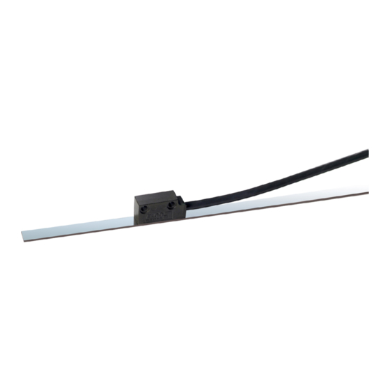
- Page 2 Operation Manual Series LMIX1 Magnetic Incremental Length Measuring System with 0.1mm resolution Sensor with external translator Direct contact free measurement The distance between sensor and magnetic tape can be between 0.1 and 2.0 mm High resolution of 0.1 mm (0.025 mm at 4 edge triggering) Repeat accuracy +/- 1 increment Insensitive against dirt...
-
Page 3: Table Of Contents
Content Content General Information ........................3 Information Operation Manual ....................3 Explanation of Symbols......................3 Statement of Warranties ......................4 Demounting and Disposal ...................... 5 Safety ............................6 General Cause of Risks ......................6 Personal Protective Equipment....................6 Conventional Use ........................7 Transport and Storage .........................7 Safety Instructions for Transport / Unpacking and Loading............ -
Page 4: General Information
General Information 1. General Information Information Operation Manual The manual contains important information regarding the handling of the sensor. Precondition for safe operation is the compliance with the specified safety and handling instructions. Moreover, observe the existing local accident prevention regulation and general safety rules. Please read the operation manual carefully before starting to work. -
Page 5: Statement Of Warranties
General Information Hints and Commendations ADVERT! ...highlights helpful hints and recommendations for efficient and failure-free operation. Specific Safety Instructions The following symbols in conjunction with safety instructions are used in order to point out possible hazards: DANGER! ...marks perilous situations by electricity. By non-observance of the safety instructions the possibility of death or severe injuries exists. -
Page 6: Demounting And Disposal
General Information Demounting and Disposal Unless otherwise authorized, dispose the item considering the safety instructions. Before demounting Disconnect the power supply Secure against re-start Disconnect supply lines physically and discharge remaining energy Dispose operating supplies with respect to the environment Disposal Recycle the decomposed elements: Scrap metal elements... -
Page 7: Safety
Safety 2 Safety General Cause of Risks This chapter gives an overview about all important safety aspects to guarantee an optimal protection of employees. Non-observance of the instructions mentioned in this operation manual can result in hazardous situations. Personal Protective Equipment Employees should wear protective clothing during installation of the device to minimize the risk of accidents. -
Page 8: Conventional Use
Transport and Storage Conventional Use The ELGO LMIX1 length measuring system is for the limited purpose as described in this manual: The LMIX1 length measuring system is constructed for measuring a distance up to 32 meter. CAUTION! Danger through non conventional use! Non-intended use and non-observance of this operation manual can lead to dangerous situations. -
Page 9: Check Of Transport
Transport and Storage Check of Transport Examine delivery immediately after receiving for completeness and transport damages. In case of externally recognizable transport damages: Do not accept the delivery or do accept under reserve Note extent of damages on the transportation documents or on the delivery note File complaint immediately ADVERT! Claim any damages you recognize as soon as possible. -
Page 10: Product Features
Product Features 4 Product Features The LMIX1 is an incremental magnetic length measuring system. The sensor technology and translator are placed in two different housings (Sensor in sensor head and translation unit in external Sub-D connector). The magnetic tape of the series MB2020 can also be fixed into a guiding rail with the provided sticky tape. The LMIX1 can be installed up to a maximum distance of 2.0 mm. -
Page 11: Technical Specifications
Technical specifications 5 Technical specifications LMIX1 Power supply 10… 30 VDC / 5VDC Consumption 10… 30 VDC: max. 150mA / 5 VDC: 200 mA Signal 10… 30 V HTL / 5V TTL Resolution 0.1 mm (0.025 mm at 4 edge triggering) Repeating Accuracy +/- 0.1 mm Maximum operation speed... -
Page 12: Dimensions Lmix1
Technical Data Dimensions LMIX1 side view Active sensor area lower side size 10 mm max. 2.0 mm... -
Page 13: Installation/ Initial Start-Up
Installation Installation 6 Installation/ Initial start-up Mounting of the Sensor Tolerances for distance and angle must be observed. Parallel adjustment: mid of Sensor = mid of tape +/- 0.5 mm A, B , C = 0° +/- 0.5° 0,1 – 2.0 mm Distance Sensor-tape Pin assignment D-SUB Only version 5 V / 5 V-TTL order index 11... -
Page 14: Options
Options 7 Options Structure of Magnetic tape MB20-50-10-1-R The tape consists of 3 components (see Figure 1), a magnetized, flexible plastic tape (Item 3), which is connected with a steel band (Item 5) and a cover tape (item 1), which is for protection of the plastic tape. The cover tape is needed for the mechanical protection of the magnetic tape. -
Page 15: Processing Instructions For The Adjustment Of Magnetic Tapes
Options Processing instructions for the adjustment of magnetic tapes Materials to stick: The provided sticky tapes stick well on clean, dry and plain surfaces. Typical solvent for cleaning surfaces are a 50/50 mixed isopropyl-alcohol / water mixture or heptane. (Important: Please observe carefully the caution hints of the producer when using the solvent.) The surfaces of materials as copper, brass etc. -
Page 16: Sticking And Cutting
Options Sticking and Cutting Note! When gluing / sticking the magnetic tape pay attention to the marks on the magnetic tape. Improper installation delivers in correct values. A previously glued tape is destroyed after removal and cannot be reused. Before the start of the bonding are magnetic tape and masking tape to the exact length basis. -
Page 17: Interferences
Interferences 8 Interferences The following chapters describe possible causes for malfunction and the instructions to correct them. If you encounter problems check for proper installation first. Make sure that power is supplied to the system. If you observe recurring errors you might consider electrical interference suppression measures as described in section 8.2. -
Page 18: Electrical Interference Suppression
Interferences Electrical interference suppression Signal wires should be installed separately from load power lines and with a safe distance of at least 0.5 m to capacitive and inductive interferences such as contactors, relays, motors, switching power supplies, timed controllers. If interferences occur in spite of applying all above mentioned measures proceed as follows: 1. -
Page 19: Emc Information
Interferences EMC information A trouble-free operation of the measuring system devices of the company ELGO Electronic GmbH & Co KG can only be guaranteed if during assembly, wiring and operating the following basic rules are observed and adhered to: •... -
Page 20: Type Designation Lmix1
Type Designation Type Designation LMIX1 Sensor head LMIX1 - XXX - XX.X - 2 - XX - XX Series LMIX1 Version 000 = Standard 001 = 1st special Version Signal cable length 01.5 = 1.5m (Standard cable length) Resolution 1 = 0.1 mm (0.025 mm at 4 edge triggering) Supply 00 = 10-30 VDC / 10-30 VDC 01 = 10-30 VDC / 5V-TTL line driver... -
Page 21: Index
Conventional Use Demounting Dimensions Disposal Electrical Interference Suppression General Guarantee Index Interferences Magnetic tape Maintenance Mounting Sensor Head Operation Manual Protective Clothing Security Type Designation Dok.-Nr. 799000071 LMIX1-000-E_06-09 Subject to change - © 2009 ELGO Electronic GmbH & Co. KG...
Need help?
Do you have a question about the LMIX1 Series and is the answer not in the manual?
Questions and answers