
Related Manuals for DFI SH960MD-CM236


Summary of Contents for DFI SH960MD-CM236
- Page 1 SH960MD-CM236/QM170/HM170 COM Express Basic Module User’s Manual Preliminary Preliminary Version Version A-520-M-2002...
-
Page 2: Trademarks
Copyright FCC and DOC Statement on Class B This publication contains information that is protected by copyright. No part of it may be repro- This equipment has been tested and found to comply with the limits for a Class B digital duced in any form or by any means or used to make any transformation/adaptation without the device, pursuant to Part 15 of the FCC rules. -
Page 3: Table Of Contents
Table of Contents Power and GND Signal Descriptions ................28 Copyright ............................2 Module type Signal Descriptions ..................28 Trademarks ............................ 2 Chapter 3 - BIOS Setup .......................29 FCC and DOC Statement on Class B ................... 2 Overview ..........................29 Main ............................30 Notice: ............................2 Advanced ..........................30 About this Manual ......................... -
Page 4: About This Manual
About this Manual Static Electricity Precautions This manual can be downloaded from the website, or acquired as an electronic file included in It is quite easy to inadvertently damage your PC, system board, components or devices even the optional CD/DVD. The manual is subject to change and update without notice, and may be before installing them in your system unit. -
Page 5: About The Package
About the Package The package contains the following items. If any of these items are missing or damaged, please contact your dealer or sales representative for assistance. • One SH960MD-CM236/QM170/HM170 board • CPU Cooler Optional Items • COM332-B carrier board kit •... - Page 6 Chapter 1 INTRODUCTION Chapter 1 - Introduction X Specifications SYSTEM Processor 6th Generation Intel Core Processors, BGA 1440 4 x USB 3.0 ® - Xeon ® E3-1515M v5 Processor, Quad Core, 8M Cache, 2.8GHz (3.7GHz), 8 x USB 2.0 45W (Support ECC) SATA 4 x SATA 3.0 (up to 6Gb/s) - Core™...
- Page 7 Chapter 1 INTRODUCTION X Features Watchdog Timer ACPI STR The Watchdog Timer function allows your application to regularly “clear” the system at the set The system board is designed to meet the ACPI (Advanced Configuration and Power Interface) time interval. If the system hangs or fails to function, it will reset at the set time interval so that specification.
- Page 8 IPC designs would typically require an entire makeover. The SH960MD is a Type 6 COM Express (R2.1) module compatible with DFI's proprietary carrier COM Express module can be replaced when there is only need to upgrade for higher computing board —...
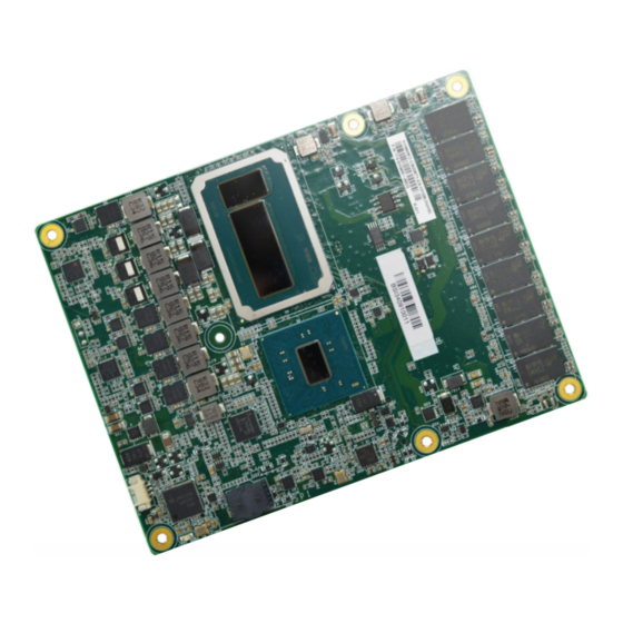
- Page 9 Chapter 2 HARDWARE INSTALLATION Chapter 2 - Hardware Installation X Board Layout Important: Electrostatic discharge (ESD) can damage your board, processor, disk drives, Top View add-in boards, and other components. Perform installation procedures at an ESD workstation only. If such a station is not available, you can provide some ESD pro- tection by wearing an antistatic wrist strap and attaching it to a metal part of the system chassis.
- Page 10 Chapter 2 HARDWARE INSTALLATION X System Memory X Assembly A CPU cooler is included in the standard package. The CPU cooler contains six spring screws and shall be installed after the COM Express module is securely mounted onto the carrier board.
- Page 11 Chapter 2 HARDWARE INSTALLATION Assembly 1. Locate the COM Express board-to-board connectors on the bottom side of the module 2. Place the module on the carrier board while making sure the mounting holes and con- and the carrier board. Locate the mounting holes on the module and the corresponding nectors all align.
- Page 12 Chapter 2 HARDWARE INSTALLATION Assembly X I/O Connectors 4. Inspect whether the gaps between the module and the stand-offs all close up. It is CPU Fan highly recommended that the module be removed and installed again following the pre- vious steps when there is discernable gap. „...
- Page 13 Chapter 2 HARDWARE INSTALLATION I/O Connectors Row A Row B Board-to-board Connector SATA2_TX- SATA3_TX- SUS_S5# PWR_OK SATA2_RX+ SATA3_RX+ SATA2_RX- SATA3_RX- BATLOW# (S)ATA_ACT# AC/HDA_SYNC AC/HDA _SDIN1 AC/HDA _RST# AC/HDA _SDIN0 GND (FIXED) GND (FIXED) AC/HDA _BITCLK SPKR AC/HDA _SDOUT I2C_CK BIOS_DIS0# I2C_DAT THRMTRIP# THRM#...
- Page 14 Chapter 2 HARDWARE INSTALLATION I/O Connectors Board-to-board Connector Row A Row B Row C Row D LVDS_VDD_EN/eDP_VDD_EN (opt.) LVDS_B3+ RSVD RSVD LVDS_A3+ LVDS_B3- PCIE_RX6+ PCIE_TX6+ LVDS_A3- LVDS_BKLT_EN/eDP_BKLT_EN (opt.) PCIE_RX6- PCIE_TX6- GND (FIXED) GND (FIXED) GND (FIXED) GND (FIXED) LVDS_A_CK+/eDP_TX3+ (opt.) LVDS_B_CK+ PCIE_RX7+ PCIE_TX7+...
- Page 15 Chapter 2 HARDWARE INSTALLATION I/O Connectors Board-to-board Connector Row C Row D PEG_RX6- PEG_TX6- PEG_RX7+ PEG_TX7+ PEG_RX7- PEG_TX7- RSVD RSVD PEG_RX8+ PEG_TX8+ PEG_RX8- PEG_TX8- GND (FIXED) GND (FIXED) PEG_RX9+ PEG_TX9+ PEG_RX9- PEG_TX9- RSVD RSVD PEG_RX10+ PEG_TX10+ PEG_RX10- PEG_TX10- PEG_RX11+ PEG_TX11+ PEG_RX11- PEG_TX11- GND (FIXED)
- Page 16 Chapter 2 HARDWARE INSTALLATION X Signal Descriptions Pin Types Input to the Module Output from the Module Bi-directional input / output signal Open drain output RSVD pins are reserved for future use and should be no connect. Do not tie the RSVD pins together. HDA Signals Descriptions Signal Pin#...
- Page 17 Chapter 2 HARDWARE INSTALLATION SATA Signals Descriptions Signal Pin# Pin Type Pwr Rail /Tolerance SH960MD PU/PD Module Base Specification R2.1 Description COM Express Carrier Design Guide R2.0 Description SATA0_TX+ O SATA AC coupled on Module AC Coupling Serial ATA or SAS Channel 0 transmit differential pair. Serial ATA channel 0 capacitor Transmit output differential pair.
- Page 18 Chapter 2 HARDWARE INSTALLATION PCI Express Lanes Signals Descriptions Signal Pin# Pin Type Pwr Rail /Tolerance SH960MD PU/PD Module Base Specification R2.1 Description COM Express Carrier Design Guide R2.0 Description PCIE_TX0+ O PCIE AC coupled on Module AC Coupling PCI Express Differential Transmit Pairs 0 PCIe channel 0.
- Page 19 Chapter 2 HARDWARE INSTALLATION PEG Signals Descriptions Signal Pin# Pin Type Pwr Rail /Tolerance SH960MD PU/PD Module Base Specification R2.1 Description COM Express Carrier Design Guide R2.0 Description PEG_TX0+ O PCIE AC coupled on Module AC Coupling PCI Express Graphics transmit differential pairs 0 PEG channel 0, Transmit Output differential pair.
- Page 20 Chapter 2 HARDWARE INSTALLATION PEG_RX10+ I PCIE AC coupled off Module PCI Express Graphics receive differential pairs 10 PEG channel 10, Receive Input differential pair. PEG_RX10- PEG_TX11+ O PCIE AC coupled on Module AC Coupling PCI Express Graphics transmit differential pairs 11 PEG channel 11, Transmit Output differential pair.
- Page 21 Chapter 2 HARDWARE INSTALLATION USB4+ I/O USB 3.3V Suspend/3.3V USB differential pairs, channel 4 USB Port 4, data + or D+ USB4- USB Port 4, data - or D- USB5+ I/O USB 3.3V Suspend/3.3V USB differential pairs, channel 5 USB Port 5, data + or D+ USB5- USB Port 5, data - or D- USB6+...
- Page 22 Chapter 2 HARDWARE INSTALLATION LVDS Signals Descriptions Signal Pin# Pin Type Pwr Rail /Tolerance SH960MD PU/PD Module Base Specification R2.1 Description COM Express Carrier Design Guide R2.0 Description LVDS_A0+/ O LVDS LVDS LVDS Channel A differential pairs LVDS channel A differential signal pair 0 eDP_TX2+ EDP: AC coupled off Ther LVDS flat panel differential pairs (LVDS_A[0:3]+/-, LVDS_B[0:3]+/-...
- Page 23 Chapter 2 HARDWARE INSTALLATION LPC Signals Descriptions Signal Pin# Pin Type Pwr Rail /Tolerance SH960MD PU/PD Module Base Specification R2.1 Description COM Express Carrier Design Guide R2.0 Description LPC_AD0 I/O CMOS 3.3V / 3.3V LPC multiplexed address, command and data bus. LPC multiplexed command, address and data.
- Page 24 Chapter 2 HARDWARE INSTALLATION DDI Signals Descriptions Signal Pin# Pin Type Pwr Rail /Tolerance SH960MD PU/PD Module Base Specification R2.1 Description COM Express Carrier Design Guide R2.0 Description DDI1_PAIR0+ O PCIE AC coupled off Module DDI for Display Port: DP1_LANE 0 differential pairs DP1_LANE0+ for DP / TMDS1_DATA2+ for HDMI or DDI for SDVO: SDVO1_RED±...
- Page 25 Chapter 2 HARDWARE INSTALLATION DDI2_PAIR0+ O PCIE AC coupled off Module DDI for Display Port: DP2_LANE 0 differential pairs DP2_LANE0+ for DP / TMDS2_DATA2+ for HDMI or DDI for HDMI/DVI: TMDS2_DATA lanes 2 differential pairs DDI2_PAIR0- DP2_LANE0- for DP / TMDS2_DATA2- for HDMI or DDI2_PAIR1+ O PCIE AC coupled off Module...
- Page 26 Chapter 2 HARDWARE INSTALLATION DDI3_PAIR3+ O PCIE AC coupled off Module DDI for Display Port: DP3_LANE 3 differential pairs DP3_LANE3+ for DP / TMDS3_CLK+ DDI for HDMI/DVI: TMDS3_CLK differential pairs DDI3_PAIR3- DP3_LANE3- for DP / TMDS3_CLK- DDI3_ I/O PCIE AC coupled on Module PD 100K to GND DDI for Display Port: DP3_AUX+ Differetial pairs DP3_AUX+ for DP CTRLCLK_...
- Page 27 Chapter 2 HARDWARE INSTALLATION Miscellaneous Signal Descriptions Signal Pin# Pin Type Pwr Rail /Tolerance SH960MD PU/PD Module Base Specification R2.1 Description COM Express Carrier Design Guide R2.0 Description SPKR O CMOS 3.3V / 3.3V Output for audio enunciator - the “speaker” in PC-AT systems. Output used to control an external FET or a logic This port provides the PC beep signal and is mostly intended for gate to drive an external PC speaker.
- Page 28 Chapter 2 HARDWARE INSTALLATION BATLOW# I CMOS 3.3V Suspend/ 3.3V PU 10KΩ to 3.3V Indicates that external battery is low. Battery low input. This signal may be driven low by Suspend This port provides a battery-low signal to the Module for orderly external circuitry to signal that the system battery is transitioning to power saving or power cut-off ACPI modes.
- Page 29 Chapter 2 HARDWARE INSTALLATION Power and GND Signal Descriptions Signal Pin# Pin Type Pwr Rail /Tolerance SH960MD PU/PD Module Base Specification R2.1 Description COM Express Carrier Design Guide R2.0 Description VCC_12V A104~A109 Power Primary power input: +12V nominal. All available VCC_12V pins on the B104~B109 connector(s) shall be used.
- Page 30 Chapter 3 BIOS SETTING Chapter 3 - BIOS Setup Legends X Overview The BIOS is a program that takes care of the basic level of communication between the CPU Keys Function and peripherals. It contains codes for various advanced features found in this system board. The BIOS allows you to configure the system and save the configuration in a battery-backed Right / Left arrow Move the highlight left or right to select a menu...
- Page 31 Chapter 3 BIOS SETTING X Main X Advanced The Main menu is the first screen that you will see when you enter the BIOS Setup Utility. The Advanced menu allows you to configure your system for basic operation. Some entries are defaults required by the system board, while others, if enabled, will improve the performance of your system or let you set some features according to your preference.
- Page 32 Chapter 3 BIOS SETTING Advanced Advanced ACPI Configuration CPU Configuration InsydeH2O Setup Utility Rev. 5.0 InsydeH2O Setup Utility Rev. 5.0 Advanced Advanced Enable/disable CPU Power C-States <Enabled> ACPI Configuration When enable ERP, Wake On Management. Allows CPU Intel(R) SpeedStep(tm) <Enabled> Lan had no function to go to C States when it’s Turbo Mode...
- Page 33 Chapter 3 BIOS SETTING Advanced Advanced Video Configuration Audio Configuration InsydeH2O Setup Utility Rev. 5.0 InsydeH2O Setup Utility Rev. 5.0 Advanced Advanced Select which of IGFX/PEG/ Control Detection of the Video Configuration HD Audio <Enabled> PCI Graphics device should HD-Audio device. be Primary Display or select Primary Display <Auto>...
- Page 34 Chapter 3 BIOS SETTING Advanced Advanced SATA Configuration USB Configuration InsydeH2O Setup Utility Rev. 5.0 InsydeH2O Setup Utility Rev. 5.0 Advanced Advanced SATA Controller(s) <Enabled> Enable/Disable SATA USB BIOS Support <Enabled> USB keyboard/mouse/stor- SATA Mode Selection <AHCI> Device. age support under UEFI Serial ATA Port 0 [Not Installed] environment.
- Page 35 Chapter 3 BIOS SETTING Advanced Advanced PCI Express Configuration ME Configuration InsydeH2O Setup Utility Rev. 5.0 Configure Management Engine related settings in this page. Advanced PCI Express Root Port 1 PCI Express Root Port 1 PCI Express Root Port 2 Settings.
-
Page 36: Sio Ite8528E
Chapter 3 BIOS SETTING Advanced SIO ITE8528E X PC Health Status InsydeH2O Setup Utility Rev. 5.0 InsydeH2O Setup Utility Rev. 5.0 Advanced Advanced COM Port 1 <Enabled> Configure Serial port us- Voltage Base I/O Address <3F8> ing options: [Disable] No VCORE 0. -
Page 37: Security
Chapter 3 BIOS SETTING X Security X Boot InsydeH2O Setup Utility Rev. 5.0 InsydeH2O Setup Utility Rev. 5.0 Main Advanced Security Boot Exit Security Current TPM Device <TPM 2.0 (FTPM)> W h e n H i d d e n , d o n ’ t e x - Numlock <On>... - Page 38 Chapter 3 BIOS SETTING Boot Boot PXE Boot capability X Legacy This field is only available when "Boot Type" is set to “UEFI Boot Type” or “Dual Boot Type”, and Configure boot priorities in this submenu. Re-arrange the order by pressing -/+ or F5/F6 to when "Network Stack"...
-
Page 39: Exit
BIOS with the flash utility. For updating Insyde BIOS in UEFI mode, you may refer to the how-to video at https://www.dfi.com/tw/knowledge/video/31. InsydeH2O Setup Utility Rev. 5.0... -
Page 40: Chapter 4 - Supported Software
Intel chipset can be recognized and configured properly in the system. tives, from a DVD included in the shipment, or from the website download page at https://www. dfi.com/DownloadCenter. 1. Setup is ready to install the util- ity. Click “Next”. -
Page 41: Intel Hd Graphics Drivers
Chapter 4 SUPPORTED SOFTWARE X Intel HD Graphics Drivers 3. Go through the readme docu- ment for more installation tips then click “Install”. 1. Setup is now ready to install the graphics driver. Click “Next”. 4. The step displays the installing status in the progress. -
Page 42: Realtek Audio Drivers
Chapter 4 SUPPORTED SOFTWARE X Realtek Audio Drivers 3. Go through the readme docu- ment for system requirements and installation tips then click “Next”. 1. Setup is ready to install the driver. Click “Next”. 4. Setup is now installing the driver. -
Page 43: Intel Lan Driver
Chapter 4 SUPPORTED SOFTWARE X Intel LAN Driver 4. Click “Install” to begin the in- stallation. 1. Setup is ready to install the driver. Click “Next”. 5. The step displays the installing status in the progress. 2. Click “I accept the terms in the license agreement”... -
Page 44: Intel Me Drivers
Chapter 4 SUPPORTED SOFTWARE X Intel ME Drivers 3. Click “Next” to install to the 1. Setup is ready to install the default folder, or click “Change” driver. Click “Next”. to choose another destination folder. 4. Please wait while the product 2. -
Page 45: Intel Rapid Storage Technology
Chapter 4 SUPPORTED SOFTWARE X Intel Rapid Storage Technology 3. Go through the readme docu- ment to view system require- ments and installation informa- The Intel Rapid Storage Technology is a utility that allows you to monitor the current status tion then click “Next”. - Page 46 Chapter 4 SUPPORTED SOFTWARE X Adobe Acrobat Reader 9.3 6. Click “Yes, I want to restart this computer now” to complete the installation and then click “Fin- ish”. 1. Click “Next” to install or click “Change Destination Folder” to select another folder. 2.
- Page 47 Chapter 4 SUPPORTED SOFTWARE 3. Setup is now installing the driver. 4. Click “Finish” to exit installa- tion. User's Manual | SH960MD...
Need help?
Do you have a question about the SH960MD-CM236 and is the answer not in the manual?
Questions and answers