
Related Manuals for DFI CH960-CM246


Summary of Contents for DFI CH960-CM246
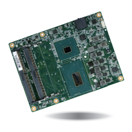
- Page 1 CH960-CM246/QM370/HM370 COM Express Basic Module User’s Manual Preliminary Version A48600910 Chapter 1 Introduction www.dfi .com...
-
Page 2: Copyright
Copyright FCC and DOC Statement on Class B This publication contains information that is protected by copyright. No part of it may be re- This equipment has been tested and found to comply with the limits for a Class B digital produced in any form or by any means or used to make any transformation/adaptation without device, pursuant to Part 15 of the FCC rules. -
Page 3: Table Of Contents
Before Using the System Board ............51 ............... 5 Chapter 6 - RAID (CH960-CM246/QM370 only) Chapter 1 - Introduction ......58 ................6 Chapter 7 - Intel AMT Settings (CH960-CM246/QM370 only) Specifications ....................6 Features ......................7 ..........................60 Chapter 2 - Concept ............... -
Page 4: Warranty
Warranty Static Electricity Precautions 1. Warranty does not cover damages or failures that arised from misuse of the product, in- It is quite easy to inadvertently damage your PC, system board, components or devices even ability to use the product, unauthorized replacement or alteration of components and prod- before installing them in your system unit. -
Page 5: About The Package
About the Package The package contains the following items. If any of these items are missing or damaged, please contact your dealer or sales representative for assistance. • One CH960-CM246/QM370/HM370 board • One Cooler (Height: 36.58mm) Optional Items • COM332-B carrier board kit •... -
Page 6: Chapter 1 - Introduction
Chapter 1 Chapter 1 - Introduction Specifications SYSTEM Processor CH960-CM246/QM370: AUDIO Interface HD Audio 8th Generation Intel Core™ Processors, BGA 1440 ® ETHERNET Controller CH960-CM246/QM370: ® Intel Xeon E-2176M Processor, 6 Cores, 12M Cache, 2.7GHz (4.4GHz), 45W 1 x Intel I219LM with iAMT12.0 PCIe (10/100/1000Mbps) -
Page 7: Features
Chapter 1 Features • Watchdog Timer The Watchdog Timer function allows your application to regularly “clear” the system at the set time interval. If the system hangs or fails to function, it will reset at the set time interval so that your system will continue to operate. -
Page 8: Chapter 2 - Concept
Chapter 2 - Concept COM Express Module Standards The figure below shows the dimensions of the different types of COM Express modules. CH960-CM246/QM370/HM370 is a COM Express Basic module. Its dimension is 95mm x 125mm. Common for all Form Factors Extended only... -
Page 9: Specification Comparison Table
Chapter 2 Specification Comparison Table The table below shows the COM Express standard specifications and the corresponding specifications supported on the CH960-CM246/QM370/HM370 module. Module Pin-out - Required and Optional Features A-B Connector. COM Express Module Base Specification DFI CH960 COM Express Module Base Specification... -
Page 10: Chapter 3 - Hardware Installation
Chapter 3 Chapter 3 - Hardware Installation Board Layout Standby Power LED Intel BGA 1440 Core Standby Power LED CPU fan Intel PTN3460 CM246/QM370/HM370 CPU fan Intel I219LM CH7517 SPI Flash BIOS Top View IT8528E TPM (optional) D110 COM Express Connector C110 B110 COM Express Connector... -
Page 11: Block Diagram
SATA 3.0 4x SATA 3.0 4x SATA 3 0 4x SATA 3.0 4x SATA 3.0 4x SATA 3 0 4x SPI Bus SPI B SPI Bus SPI B SPI Flash SPI Flash CH960-CM246/QM370 CH960-HM370 Chapter 3 Hardware Installation www.dfi .com... -
Page 12: System Memory
Chapter 3 Installing the SODIMM Module Important: Electrostatic discharge (ESD) can damage your board, processor, disk drives, add-in boards, and other components. Perform installation procedures at an ESD workstation Note: only. If such a station is not available, you can provide some ESD protection by wear- The system board used in the following illustrations may not resemble the actual one. -
Page 13: Connectors
Chapter 3 5. Grasping the module by its edges, align the module into the socket at an approximately 30 Connectors degrees angle. Apply firm even pressure to each end of the module until it slips down into the socket. The contact fingers on the edge of the module will almost completely disappear CPU Fan Connector inside the socket. -
Page 14: Com Express Connectors
Express board to a carrier board. Connect the COM Express connectors (located on the solder side of the board) to the COM Express connectors on the carrier board. Refer to the “Installing CH960-CM246/QM370/HM370 onto a Carrier Board” section for more information. - Page 15 Chapter 3 COM Express Connectors-Continued Row A Row B Row A Row B Row C Row D Row C Row D GND (FIXED) GND (FIXED) PCIE_TX4- PCIE_RX4- GND (FIXED) GND (FIXED) PEG_RX1- PEG_TX1- GBE0_MDI3- GBE0_ACT# GPO2 GBE0_MDI3+ LPC_FRAME# PCIE_TX3+ PCIE_RX3+ USB_SSRX0- USB_SSTX0- PEG_RX2+...
-
Page 16: Com Express Connectors Signals And Descriptions
Chapter 3 COM Express Connectors Signals and Descriptions Pin Types Input to the Module Output from the Module I/O Bi-directional input / output signal OD Open drain output RSVD pins are reserved for future use and should be no connect. Do not tie the RSVD pins together. AC97/HDA Signals Descriptions Signal Pin#... - Page 17 Chapter 3 PCI Express Lanes Signals Descriptions Signal Pin# Pin Type Pwr Rail /Tolerance CH960 PU/PD Module Base Specification R2.1 Description COM Express Carrier Design Guide R2.0 Description PCIE_TX0+ AC Coupling capacitor O PCIE AC coupled on Module PCI Express Differential Transmit Pairs 0 PCIe channel 0.
- Page 18 Chapter 3 PEG Signals Descriptions Signal Pin# Pin Type Pwr Rail /Tolerance CH960 PU/PD Module Base Specification R2.1 Description COM Express Carrier Design Guide R2.0 Description PEG_TX6+ AC Coupling capacitor O PCIE AC coupled on Module PCI Express Graphics transmit differential pairs 6 PEG channel 6, Transmit Output differential pair.
- Page 19 Chapter 3 USB Signals Descriptions Signal Pin# Pin Type Pwr Rail /Tolerance CH960 PU/PD Module Base Specification R2.1 Description COM Express Carrier Design Guide R2.0 Description USB2+ USB Port 2, data + or D+ I/O USB 3.3V Suspend/3.3V USB differential pairs, channel 2 USB2- USB Port 2, data - or D- USB3+...
- Page 20 Chapter 3 USB Signals Descriptions Signal Pin# Pin Type Pwr Rail /Tolerance CH960 PU/PD Module Base Specification R2.1 Description COM Express Carrier Design Guide R2.0 Description USB_SSRX2+ USB Port 2, SuperSpeed RX + Additional receive signal differential pairs for the SuperSpeed USB data I PCIE AC coupled off Module path.
- Page 21 Chapter 3 LPC Signals Descriptions Signal Pin# Pin Type Pwr Rail /Tolerance CH960 PU/PD Module Base Specification R2.1 Description COM Express Carrier Design Guide R2.0 Description LPC_AD0 LPC_AD1 I/O CMOS 3.3V / 3.3V LPC multiplexed address, command and data bus. LPC multiplexed command, address and data.
- Page 22 Chapter 3 DDI Signals Descriptions Signal Pin# Pin Type Pwr Rail /Tolerance CH960 PU/PD Module Base Specification R2.1 Description COM Express Carrier Design Guide R2.0 Description DDI for Display Port: DP1_LANE 2 differential pairs DDI1_PAIR2+ DP1_LANE2+ for DP / TMDS1_DATA0+ for HDMI or DVI DDI for SDVO: SDVO1_BLU±...
- Page 23 Chapter 3 DDI Signals Descriptions Signal Pin# Pin Type Pwr Rail /Tolerance CH960 PU/PD Module Base Specification R2.1 Description COM Express Carrier Design Guide R2.0 Description PU 100K to 3.3V DDI for Display Port: DP2_AUX- Differetial pairs (S/W IC between (DP AUX- function if DDI2_DDC_AUX_SEL is no connect) I/O PCIE AC coupled on Module...
- Page 24 Chapter 3 I2C Signal Descriptions Signal Pin# Pin Type Pwr Rail /Tolerance CH960 PU/PD Module Base Specification R2.1 Description COM Express Carrier Design Guide R2.0 Description I2C_CK I/O OD CMOS 3.3V Suspend/3.3V PU 2.2K to 3.3V Suspend General purpose I2C port clock output General Purpose I2C Clock output I2C_DAT I/O OD CMOS 3.3V Suspend/3.3V...
- Page 25 Chapter 3 Thermal Protection Signals Descriptions Signal Pin# Pin Type Pwr Rail /Tolerance CH960 PU/PD Module Base Specification R2.1 Description COM Express Carrier Design Guide R2.0 Description Thermal Alarm active low signal generated by the external THRM# I CMOS 3.3V / 3.3V PU 10K Input from off-Module temp sensor indicating an over-temp situation.
- Page 26 Chapter 3 Power and GND Signal Descriptions Signal Pin# Pin Type Pwr Rail /Tolerance CH960 PU/PD Module Base Specification R2.1 Description COM Express Carrier Design Guide R2.0 Description A1, A11, A21, A31, A41, A51, A57, A60, A66, A70, A80, A90, A100, A110, B1, B11, B21 ,B31, B41, B51,...
-
Page 27: Standby Power Led
Bottom View of the Heat Sink • “1” and “2” denote the locations of the thermal pads designed to contact the corresponding components on CH960-CM246/QM370/HM370. Important: Remove the plastic covering from the thermal pads prior to mounting the heat sink onto CH960-CM246/QM370/HM370. -
Page 28: Installing Ch960-Cm246/Qm370/Hm370 Onto A Carrier Board
Pressing points 1. Grasp CH960-CM246/QM370/HM370 by its edges and position it on top of the carrier board with its mounting holes aligned with the standoffs on the carrier board. This helps align the COM Express connectors of the two boards to each other. - Page 29 Chapter 3 3. Install a heat sink onto the CH960 with the carrier board. First align the mounting holes of the heat sink with the mounting holes of the module. Heat sink CH960 Carrier board Side View of the Heat sink, Module, and Carrier Board Note: Install the heat sink according to the sequence of the screws shown in the image above to avoid damages to the CPU.
-
Page 30: Chapter 4 - Bios Setup
Chapter 4 Chapter 4 - BIOS Setup Legends Overview KEYs Function The BIOS is a program that takes care of the basic level of communication between the CPU Right and Left Arrows Moves the highlight left or right to select a menu. and peripherals. -
Page 31: Ami Bios Setup Utility
Chapter 4 AMI BIOS Setup Utility Aptio Setup Utility - Copyright (C) 2019 American Megatrends, Inc. Main Advanced Chipset Security Boot Save & Exit Main BIOS Version B191.25A Set the Date. Use Tab EC Version 2019.01.22 v0.8 to switch between Date elements. -
Page 32: Advanced
Chapter 4 Advanced RC ACPI Settings The Advanced menu allows you to configure your system for basic operation. Some entries are This section is used to configure the system ACPI parameters. defaults required by the system board, while others, if enabled, will improve the performance of your system or let you set some features according to your preference. - Page 33 Chapter 4 CPU Configuration Aptio Setup Utility - Copyright (C) 2019 American Megatrends, Inc. Advanced This section is used to configure the CPU. RC ACPI Settings select 0-23 For example enter 3 for 3am and 15 [Enabled] Wake system from S5 for 3pm Aptio Setup Utility - Copyright (C) 2019 American Megatrends, Inc.
- Page 34 This field is used to enable or disable processor turbo mode (requires that Intel(R) SpeedStep(tm) is enabled too), which allows the processor core to automatically run AMT BIOS Features (for CH960-CM246/QM370 only) faster than the base frequency when the processor’s power, temperature, and specifi- cation are within the limits of TDP.
- Page 35 Chapter 4 Aptio Setup Utility - Copyright (C) 2019 American Megatrends, Inc. Aptio Setup Utility - Copyright (C) 2019 American Megatrends, Inc. Advanced Advanced ME State [Enabled] Confi gure Intel(R) Active USB Provisioning of AMT [Disabled] Enable/Disable of AMT Manageability Features State [Enabled] Management Technology Secure Erase Confi...
- Page 36 Chapter 4 Aptio Setup Utility - Copyright (C) 2019 American Megatrends, Inc. Aptio Setup Utility - Copyright (C) 2019 American Megatrends, Inc. Advanced Advanced ME State [Enabled] Confi gure Management USB Provisioning of AMT [Disabled] Confi gure OEM Flags Manageability Features State [Enabled] Engine Technology ...
- Page 37 Chapter 4 Trusted Computing PTN3460 Configuration This section configures settings relevant to Trusted Computing innovations. This section is used to configure the PTN3460 parameters. Aptio Setup Utility - Copyright (C) 2019 American Megatrends, Inc. Aptio Setup Utility - Copyright (C) 2019 American Megatrends, Inc. Advanced Advanced TPM20 Device Found...
- Page 38 Chapter 4 WatchDog Configuration IT8528 Super IO Configuration This section configures WatchDog parameters. This section is used to configure the I/O functions supported by the onboard Super I/O chip. Aptio Setup Utility - Copyright (C) 2019 American Megatrends, Inc. Aptio Setup Utility - Copyright (C) 2019 American Megatrends, Inc. Advanced Advanced IT8528 Super IO Confi...
- Page 39 Chapter 4 Serial Port Console Redirection Aptio Setup Utility - Copyright (C) 2019 American Megatrends, Inc. Advanced This section configures settings relevant to serial port console redirection. COM1 Emulation: ANSI: Console Redirection Settings Extended ASCII char set. VT100: ASCII char set. Aptio Setup Utility - Copyright (C) 2019 American Megatrends, Inc.
- Page 40 Chapter 4 Network Stack Configuration USB Configuration This section is used to configure the Network Stack settings. This section is used to configure the USB settings. Aptio Setup Utility - Copyright (C) 2019 American Megatrends, Inc. Aptio Setup Utility - Copyright (C) 2019 American Megatrends, Inc. Advanced Advanced USB Confi...
- Page 41 Chapter 4 CSM Configuration Ipv4 PXE Support This section is used to configure the CSM settings. Enable or disable IPv4 PXE boot support. If disabled, IPv4 PXE boot support will not be available. Aptio Setup Utility - Copyright (C) 2019 American Megatrends, Inc. Advanced Ipv6 PXE Support Compatibility Support Module Confi...
- Page 42 Chapter 4 PC Health Status Boot option filter This section displays the hardware health monitor and also configures smart fans. This field controls Legacy/UEFI ROMs priority. Network Aptio Setup Utility - Copyright (C) 2019 American Megatrends, Inc. Advanced This field controls the execution of UEFI and Legacy Network OpROM. PC Health Status Smart Fan function setting...
- Page 43 Chapter 4 Note: Aptio Setup Utility - Copyright (C) 2019 American Megatrends, Inc. CPU Smart Fan Control and System Smart Fan Control can be switched to [Disabled]. Advanced When they are disabled, "Fix Fan Speed Count" will appear for configuration. Smart Fan Function Enable CPU SmartFan [Enabled]...
-
Page 44: Chipset
Chapter 4 Graphics Configuration Chipset This section configures the Graphics setting. This section configures relevant chipset functions. Aptio Setup Utility - Copyright (C) 2019 American Megatrends, Inc. Chipset Graphics Confi guration Initial priority : Aptio Setup Utility - Copyright (C) 2019 American Megatrends, Inc. AUTO: PEG->PCIe->PCI- Main Advanced... - Page 45 Chapter 4 PEG Port Configuration PCH-IO Configuration This section configures the PEG port. This section illustrates the PCH parameters. Aptio Setup Utility - Copyright (C) 2019 American Megatrends, Inc. Aptio Setup Utility - Copyright (C) 2019 American Megatrends, Inc. Chipset Chipset PEG Port Confi...
- Page 46 RST Legacy OROM” field will show up for configuration. Hot Plug Use RST Legacy OROM (for CH960-CM246/QM370 only) Enable or disable the hot plug function of the PCI Express root port. Enable or disable to use RST Legacy OROM when CSM is enabled.
-
Page 47: Security
Chapter 4 Security Aptio Setup Utility - Copyright (C) 2019 American Megatrends, Inc. Chipset Control Detection of the HD Audio Subsystem Confi guration Settings Aptio Setup Utility - Copyright (C) 2019 American Megatrends, Inc. HD-Audio device. Disabled = HDA will be Main Advanced Chipset... -
Page 48: Boot
Chapter 4 Boot Note: If "Boot option filter" is set to "UEFI and Legacy" or "UEFI only" and "Quiet Boot" is set to enabled, "BGRT Logo" field will show up for configuration. Refer to the Advanced > CSM Configuration for more information. Aptio Setup Utility - Copyright (C) 2019 American Megatrends, Inc. -
Page 49: Save & Exit
Main Advanced Chipset Security Boot Save & Exit update AMI BIOS in UEFI mode on DFI products?, at https://www.dfi.com/Knowledge/Video/5 Save Options Reset the system after for updating the BIOS steps. saving the changes Save Changes and Reset Discard Changes and Reset... -
Page 50: Notice: Bios Spi Rom
Chapter 4 Notice: BIOS SPI ROM 1. The Intel Management Engine has already been integrated into this system board. Due to ® the safety concerns, the BIOS (SPI ROM) chip cannot be removed from this system board and used on another system board of the same model. 2. -
Page 51: Chapter 5 - Supported Software
Please download drivers, utilities and software applications required to enhance the perfor- tion tips then click “Install”. mance of the system board at https://www.dfi.com/DownloadCenter . Intel Chipset Software Installation Utility The Intel Chipset Software Installation Utility is used for updating Windows ®... - Page 52 Chapter 5 Intel Graphics Drivers 3. Go through the readme document for system re- quirements and installation To install the driver, download “CH960 Graphics Driver” zip file at our website. tips then click “Next”. 1. Setup is now ready to install the graphics driver.
- Page 53 Chapter 5 Audio Drivers Intel LAN Drivers To install the driver, download “CH960 Audio Driver” zip file at our website. To install the driver, download “CH960 LAN Driver” zip file at our website. 1. Setup is ready to install the 1.
- Page 54 Chapter 5 Intel Management Engine Drivers 4. Click “Install” to begin the installation. To install the driver, download “CH960 MEI Driver” zip file at our website. 1. Setup is ready to install the driver. Click “Next”. 5. The step displays the installing status in the prog- ress.
- Page 55 Chapter 5 Intel Rapid Storage Technology 3. Click “Next” to install to the default folder, or click “Change” to choose another The Intel Rapid Storage Technology is a utility that allows you to monitor the current status destination folder. of the SATA drives. It enables enhanced performance and power management for the storage subsystem.
- Page 56 Chapter 5 3. Go through the readme 6. Click “Yes, I want to restart document to view system this computer now” to requirements and installa- complete the installation tion information then click and then click “Finish”. “Next”. 4. Click “Next” to install to the default folder or click “Change to choose another destination folder”.
- Page 57 Chapter 5 Adobe Acrobat Reader 9.3 3. Setup is now installing the driver. To install the reader, download “CH960-CM246/QM370/HM370 Driver Package” iso file at our website. Click “Adobe Acrobat Reader 9.3”. 1. Click “Next” to install or click “Change Destination Folder”...
-
Page 58: Chapter 6 - Raid (Ch960-Cm246/Qm370 Only)
Chapter 6 Chapter 6 - RAID (CH960-CM246/QM370 only) Settings The system board allows configuring RAID on Serial ATA drives. It supports RAID 0, RAID 1, To enable the RAID function, the following settings are required. RAID 5 and RAID 10. - Page 59 Chapter 6 Step 4: Install the RAID Driver During OS Installation Step 5: Install the Intel Rapid Storage Technology Utility The RAID driver must be installed during the Windows ® XP or Windows ® 2000 installation us- The Intel Rapid Storage Technology Utility can be installed from within Windows. It allows ing the F6 installation method.
-
Page 60: Chapter 7 - Intel Amt Settings (Ch960-Cm246/Qm370 Only)
Chapter 7 Chapter 7 - Intel AMT Settings (CH960-CM246/QM370 only) Enable Intel AMT in the AMI BIOS ® Overview 1. Power-on the system then press <Del> to enter the main menu of the Insyde BIOS. Intel Active Management Technology (Intel ®... - Page 61 Chapter 7 4. In the Save & Exit menu, select Save Changes and Reset and then press <Enter>. Configure Intel AMT in the Intel Management Engine BIOS ® ® A dialog box will appear. Select Yes and press Enter to reset the system after saving all changes made.
- Page 62 Chapter 7 2. Select MEBx Login and press Enter. You will be prompted for a password. The default 4. You will be asked to verify the new password. Enter the same new password in the space password is “admin”. Enter the default password in the space provided under Intel(R) ME provided under Verify Password then press Enter.
- Page 63 Chapter 7 6. If you want to change ME password, select Change ME Password then press Enter. 8. You will be asked to verify the new password. Enter the same new password in the space Enter the current password in the space provided under Intel(R) ME Password then press provided under Verify Password then press Enter.
- Page 64 Chapter 7 Press Esc until you return to the Main Menu. Select Intel(R) AMT then press Enter. In the Intel(R) AMT Configuration menu, select Manageability Feature Selection Select Enabled or Disabled then press Enter. then press Enter. Select Enabled or Disabled then press Enter. Intel(R) Management Engine BIOS Extension v12.0.0.0010/Intel(R) ME v12.0.7.1122 Intel(R) Management Engine BIOS Extension v12.0.0.0010/Intel(R) ME v12.0.7.1122 Copyright(C) 2003-17 Intel Corporation.
- Page 65 Chapter 7 Select SOL then press Enter. Select Enabled or Disabled then press Enter. Select KVM Feature Selection then press Enter. Select Enabled or Disabled then press Enter. Intel(R) Management Engine BIOS Extension v12.0.0.0010/Intel(R) ME v12.0.7.1122 Intel(R) Management Engine BIOS Extension v12.0.0.0010/Intel(R) ME v12.0.7.1122 Copyright(C) 2003-17 Intel Corporation.
- Page 66 Chapter 7 In the User Consent menu, select User Opt-in then press Enter. Select NONE or KVM Press Esc until you return to the Intel(R) AMT Configuration menu. Select Password or ALL then press Enter. Policy then press Enter. You may choose to use a password only during setup and configuration or to use a pass- word anytime the system is being accessed.
- Page 67 Chapter 7 In the Intel(R) ME Network Setup menu, select Intel(R) ME Network Name Set- Select Domain Name then press Enter. Enter the computer’s domain name then press tings then press Enter. Enter. Intel(R) Management Engine BIOS Extension v12.0.0.0010/Intel(R) ME v12.0.7.1122 Intel(R) Management Engine BIOS Extension v12.0.0.0010/Intel(R) ME v12.0.7.1122 Copyright(C) 2003-17 Intel Corporation.
- Page 68 Chapter 7 Select Dynamic DNS Update then press Enter. Select Enabled or Disabled then press Select TTL then press Enter. Enter value then press Enter. Enter. If Dynamic DNS Update is set to Enabled, Periodic Update Interval and TTL fields will show up. Intel(R) Management Engine BIOS Extension v12.0.0.0010/Intel(R) ME v12.0.7.1122 Intel(R) Management Engine BIOS Extension v12.0.0.0010/Intel(R) ME v12.0.7.1122 Copyright(C) 2003-17 Intel Corporation.
- Page 69 Chapter 7 In the Wired LAN IPV4 Configuration menu, select DHCP Mode then press Enter. Select Subnet Mask Address then press Enter. Enter address then press Enter. Select Enabled or Disabled then press Enter. If set to Disabled, IPV4 Address, Subnet Mask Address, Default Gateway Address, Preferred DNS Address and Alternate DNS Address will show up.
- Page 70 Chapter 7 Select Preferred DNS Address then press Enter. Enter address then press Enter. Press Esc until you return to the Intel(R) AMT Configuration menu. If you want to activate the current network settings and open the ME network inferface, select Activate Network Access, press Enter, then press Y.
- Page 71 Chapter 7 In the Intel(R) AMT Configuration menu, select Remote Setup And Configuration In the Intel(R) Remote Setup And Configuration menu, select Provisioning Re- then press Enter. cord then press Enter. Intel(R) Management Engine BIOS Extension v12.0.0.0010/Intel(R) ME v12.0.7.1122 Intel(R) Management Engine BIOS Extension v12.0.0.0010/Intel(R) ME v12.0.7.1122 Copyright(C) 2003-17 Intel Corporation.
- Page 72 Chapter 7 In the Intel(R) Remote Setup And Configuration menu, select Provisioning Press Esc until you return to the Intel(R) Remote Setup And Configuration menu. Server FQDN then press Enter. Enter the FQDN then press Enter. Select TLS PKI then press Enter. Select Remote Configuration ** then press Enter. Select Enabled or Disabled then press Enter.
- Page 73 Chapter 7 In the Intel(R) Remote Configuration menu, select Manage Hashes then press In the Intel(R) AMT Power Control menu, select Idle Timeout then press Enter. Enter. Select the hash name then press Insert to enter custom hash certificate name, Enter the timeout value and press Enter.
Need help?
Do you have a question about the CH960-CM246 and is the answer not in the manual?
Questions and answers