
Related Manuals for DFI KH960-CM238


Summary of Contents for DFI KH960-CM238
- Page 1 KH960-CM238/QM175/HM175 COM Express Basic Module User’s Manual A45420952 Chapter 1 Introduction www.dfi.com...
-
Page 2: Copyright
Product names or trademarks appearing in this manual are for identification purpose only and 2. Shielded interface cables must be used in order to comply with the emission limits. are the properties of the respective owners. COM Express Specification Reference PICMG ® COM Express Module Base Specification. http://www.picmg.org/ Chapter 1 Introduction www.dfi.com... -
Page 3: Table Of Contents
Appendix B - Insyde BIOS Standard Status POST Code 77 Chapter 2 - Concept ..........8 COM Express Module Standards ..............8 Specification Comparison Table ................ 9 Chapter 3 - Hardware Installation......10 Board Layout......................10 Block Diagram ....................10 Chapter 1 Introduction www.dfi.com... -
Page 4: About This Manual
To reduce the risk of electric shock: • Unplug the power cord before removing the system chassis cover for installation or servic- ing. After installation or servicing, cover the system chassis before plugging the power cord. Chapter 1 Introduction www.dfi.com... -
Page 5: About The Package
• Storage devices such as hard disk drive, CD-ROM, etc. You will also need external system peripherals you intend to use which will normally include at least a keyboard, a mouse and a video display monitor. Chapter 1 Introduction www.dfi.com... -
Page 6: Chapter 1 - Introduction
Chapter 1 Chapter 1 - Introduction Specifications System Processor 7th Generation Intel Core™ Processors, BGA 1440 ® Audio Interface HD Audio Intel Xeon E3-1505M v6 Processor, Quad Core, 8M Cache, 3.0GHz (4.0GHz), 45W* ® ® Ethernet Controller 1 x Intel ®... -
Page 7: Features
USB 1.1 (12Mb/s). USB 3.0 reduces the time required for data transmission, reduces power consumption, and is backward compatible with USB 2.0. It is a marked improvement in device transfer speeds between your computer and a wide range of simultaneously accessible external Plug and Play peripherals. Chapter 1 Introduction www.dfi.com... -
Page 8: Chapter 2 - Concept
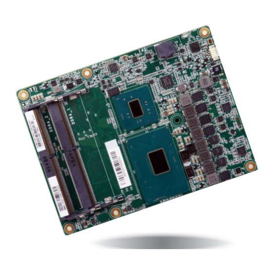
KH960 is a COM Express Basic module. Its dimension is 95mm x 125mm. Common for all Form Factors Extended only Basic only Compact only Compact and Basic only Mini only 106.00 Extended 91.00 Compact Basic 70.00 51.00 Mini 18.00 6.00 4.00 0.00 Chapter 2 Concept www.dfi.com... -
Page 9: Specification Comparison Table
Minimum (Min.) shall be implemented by all Modules. Features identified up to Maximum (M implemented by a Module. Module Pin-out - Required and Optional Features A-B Connector. Change Key: COM Express Module Base DFI KH960 Specification Type 6 Type 6 Connector Feature Table 3.2: Module Pin-out - Required and Optional Features A-B Connector... -
Page 10: Chapter 3 - Hardware Installation
Chipset PCIe (2 x1/1 x2) PCIe x1 ® Intel GLAN I219LM IT8528E USB 2.0 8x SATA 3.0 4x SPI Bus SPI Flash (optional) D110 COM Express connector C110 B110 COM Express connector A110 Bottom View Chapter 3 Hardware Installation www.dfi.com... -
Page 11: Mechanical Diagram
Chapter 3 Mechanical Diagram KH960 Heat Sink and Fan 91.00 87.00 150±5.0 19.00 70.00 36.00 30.20±0.1 4.00 45.41 11.46 0.00 4.00 4.00 76.00±0.1 41.00±0.10 0.00 2.50 14.00 Chapter 3 Hardware Installation www.dfi.com... -
Page 12: System Memory
Chapter 3 Installing the DIMM Module Important: Electrostatic discharge (ESD) can damage your board, processor, disk drives, add-in boards, and other components. Perform installation procedures at an ESD workstation Note: only. If such a station is not available, you can provide some ESD protection by wear- The system board used in the following illustrations may not resemble the actual one. -
Page 13: Connectors
CPU and board components. BIOS Setting The “Super IO Configuration” submenu in the Advanced menu of the BIOS will display the cur- rent speed of the cooling fan. Refer to chapter 4 for more information Chapter 3 Hardware Installation www.dfi.com... -
Page 14: Com Express Connectors
PICMG® COM.0 Revision 2.1 COM Express® Base Specification, Mar 28, 2012 Revision 2.1 - Draft 0.92 / Copyright PICMG (file PICMG_COM_0_R2_1_D092.odt) DRAFT Version - Do Not Design To/Do Not Claim Compliance To/Do Not Distribute This Document Chapter 3 Hardware Installation www.dfi.com... - Page 15 Revision 2.1 - Draft 0.92 / Copyright PICMG (file PICMG_COM_0_R2_1_D092.odt) DRAFT Version - Do Not Design To/Do Not Claim Compliance To/Do Not Distribute This Document DRAFT Version - Do Not Design To/Do Not Claim Compliance To/Do Not Distribute This Document Chapter 3 Hardware Installation www.dfi.com...
-
Page 16: Com Express Connectors Signals And Descriptions
SATA1_TX+ O SATA AC coupled on Module AC Coupling capacitor Serial ATA channel 1 Chapter 3 Hardware Installation www.dfi.com Serial ATA or SAS Channel 1 transmit differential pair. Transmit output differential pair. SATA1_TX- O SATA AC coupled on Module AC Coupling capacitor... - Page 17 PCI Express Differential Receive Pairs 3 PCIe channel 3. Receive Input differential pair. PCIE_RX3- PCIE_TX4+ AC Coupling capacitor Chapter 3 Hardware Installation www.dfi.com O PCIE AC coupled on Module PCI Express Differential Transmit Pairs 4 PCIe channel 4. Transmit Output differential pair. PCIE_TX4-...
- Page 18 Pin Type Pwr Rail /Tolerance KH960 PU/PD Module Base Specification R2.1 Description COM Express Carrier Design Guide R2.0 Description www.dfi.com I PCIE AC coupled off Module PCI Express Graphics receive differential pairs 3 PEG channel 3, Receive Input differential pair.
- Page 19 AC Coupling capacitor O PCIE AC coupled on Module PCI Express Graphics transmit differential pairs 12 PEG channel 12, Transmit Output differential pair. Chapter 3 Hardware Installation www.dfi.com PEG_TX9+ AC Coupling capacitor PEG_TX12- AC Coupling capacitor O PCIE AC coupled on Module PCI Express Graphics transmit differential pairs 9 PEG channel 9, Transmit Output differential pair.
- Page 20 USB differential pairs, channel 3 PEG channel 8, Receive Input differential pair. PEG_RX8- USB3- USB Port 3, data - or D- Chapter 3 Hardware Installation www.dfi.com USB4+ USB Port 4, data + or D+ PEG_TX9+ AC Coupling capacitor I/O USB 3.3V Suspend/3.3V...
- Page 21 Module Base Specification R2.1 Description COM Express Carrier Design Guide R2.0 Description LVDS LVDS_A0+/eDP_TX2+ Chapter 3 Hardware Installation www.dfi.com LVDS channel A differential signal pair 0 O LVDS EDP: AC coupled off eDP lane 2, TX ± differential signal pair...
- Page 22 LPC frame indicates start of a new cycle or termination of a LPC_FRAME# O CMOS 3.3V / 3.3V LPC frame indicates the start of an LPC cycle broken cycle. Chapter 3 Hardware Installation www.dfi.com PU 10K to 3.3V, not LPC_DRQ0#...
- Page 23 Pwr Rail /Tolerance KH960 PU/PD Module Base Specification R2.1 Description COM Express Carrier Design Guide R2.0 Description Chapter 3 Hardware Installation www.dfi.com DDI for Display Port: DP1_LANE 0 differential pairs DDI1_PAIR0+ DP1_LANE0+ for DP / TMDS1_DATA2+ for HDMI or DVI...
- Page 24 AC coupled off Module DDI for HDMI/DVI: TMDS2_DATA lanes 0 differential pairs DDI2_PAIR2- DP2_LANE2- for DP / TMDS2_DATA0- for HDMI or DVI Chapter 3 Hardware Installation www.dfi.com DDI2_PAIR3+ DP2_LANE3+ for DP / TMDS2_CLK+ DDI for Display Port: DP2_LANE 3 differential pairs...
- Page 25 (S/W IC between DDI for Display Port: DP3_AUX- Differetial pairs I/O PCIE AC coupled on Module DP3_AUX- for DP Rpu/PCH) (DP AUX- function if DDI3_DDC_AUX_SEL is no connect) Chapter 3 Hardware Installation DDI3_CTRLCLK_AUX- www.dfi.com PU 2.2K to 3.3V/PU 100K to 3.3V...
- Page 26 PU 10KΩ to 3.3V Suspend not able to reestablish control of the system, PWR_OK or a power SYS_RESET# is not able to reestablish control of the system, cycle may be used. PWR_OK or a power cycle may be used. Chapter 3 Hardware Installation www.dfi.com...
- Page 27 Module Base Specification R2.1 Description COM Express Carrier Design Guide R2.0 Description PU 2.2KΩ to 3.3V Chapter 3 Hardware Installation SMB_CK I/O OD CMOS 3.3V Suspend/3.3V System Management Bus bidirectional clock line. System Management Bus bidirectional clock line www.dfi.com Suspend...
- Page 28 C76, C80, C84, GND plane. C87, C90, C93, C96, C100, C103, C110, D1, D2, D5, D8, D11, D14, D21, D31, D41,D51, D60, D67, D70, D73, D76, D80, D84, D87, D90, D93, D96, D100, D103, D110 Chapter 3 Hardware Installation www.dfi.com...
- Page 29 1-6. A Carrier can detect a R1.0 Module by the presence of 12V on this pin. R2.0 Module types 1-6 will no connect this pin. Type 10 Modules shall pull this pin to ground through a 47K resistor. Chapter 3 Hardware Installation www.dfi.com...
-
Page 30: Standby Power Led
“1” and “2” denote the locations of the thermal pads designed to contact the corresponding components on KH960. Important: Remove the plastic covering from the thermal pads prior to mounting the heat sink onto KH960. Chapter 3 Hardware Installation www.dfi.com... - Page 31 BIOS ROM socket COM Express connectors on the carrier board Note: The above illustration shows the pressing points of the module onto the carrier board. Be careful when pressing the module to avoid damaging the socket. Chapter 3 Hardware Installation www.dfi.com...
- Page 32 Install the heatsink according to the sequence of the screws shown in the above im- age to avoid damaging the CPU. 4. Connect the heatsink and fan’s cable to the fan connector on KH960. Fan connector Chapter 3 Hardware Installation www.dfi.com...
-
Page 33: Chapter 4 - Bios Setup
“Press DEL to run setup” will appear on the screen. If the message disappears before you respond, restart the system or press the “Reset” button. You may also restart the system by pressing the <Ctrl> <Alt> and <Del> keys simultaneously. Chapter 4 BIOS Setup www.dfi.com... -
Page 34: Insyde Bios Setup Utility
The time format is <hour>, <minute>, <second>. The time is based on the 24-hour military-time clock. For example, 1 p.m. is 13:00:00. Hour displays hours from 00 to 23. Minute displays minutes from 00 to 59. Second displays seconds from 00 to 59. Chapter 4 BIOS Setup www.dfi.com... - Page 35 Automatically power the system on at a particular time every day from the Real-time needs to be set to “disabled” before installation. clock battery. Specify the wake up time of the day below: <hour>, <minute>, <sec- ond>. Chapter 4 BIOS Setup www.dfi.com...
- Page 36 Select either integrated graphics function (IGFX) or PCIe graphics device (PEG) to be the primary display. Note that this option is only available if the boot type is set to “Dual” or “UEFI”. Internal Graphics Device Enable or disable the integrated graphics function (IGFX). Chapter 4 BIOS Setup www.dfi.com...
- Page 37 Control the detection of the High-Definition Audio device. DC mode. Disabled High Definition Audio will be unconditionally disabled. Enabled High Definition Audio will be unconditionally enabled. Auto High Definition Audio will be enabled if present and disabled otherwise. Chapter 4 BIOS Setup www.dfi.com...
- Page 38 This option allows you to create RAID using Intel Rapid Storage Technology on the ® Serial ATA devices. Serial ATA Port 0, 1, 2, and 3 Hot Plug Enable or disable each Serial ATA port and its hot plug function. Chapter 4 BIOS Setup www.dfi.com...
- Page 39 PCIe Speed Select the speed of the PCI Express Root Port: Auto, Gen1 (2.5 GT/s), Gen2 (5 GT/s) or Gen3 (8 GT/s). Hot Plug Enable or disable the hot plug function of each PCIe root port. Chapter 4 BIOS Setup www.dfi.com...
- Page 40 Enable or disable the Intel ® Active Management Technology (AMT) support of the BIOS. Un-Configure ME Enable to clear all settings of the Intel Active Management Technology (AMT) without ® requiring a password on the next boot. Chapter 4 BIOS Setup www.dfi.com...
- Page 41 Enter or choose the serial port number for message output. The options are COM1 (0x3F8) and COM2 (0x2F8). EFI Debug baud rate Enter or choose the baud rate for serial communication. The default is 115200. Chapter 4 BIOS Setup www.dfi.com...
- Page 42 WDT. Input any value between 1 to 255 seconds. PC Health Status COM Port 1 to COM Port 2 The screen displays the PC health status such as the CPU temperature and fan speeds. Enable or disable each serial port. Chapter 4 BIOS Setup www.dfi.com...
-
Page 43: Security
Alternatively, choose to use the pre-configured global If you select to set the supervisor password, this option will be shown. Enable or dis- settings from the previous menu. able the system to require password at boot. Chapter 4 BIOS Setup www.dfi.com... -
Page 44: Boot
Enable or disable boot from USB devices. has the highest boot priority. Note: If the boot type is set to UEFI, the method for RAID volume creation will be different. Please refer to Chapter 6 for more information. Chapter 4 BIOS Setup www.dfi.com... - Page 45 For example, to boot from a floppy drive instead of a operating system’s boot files. hard drive, place the floppy drive ahead of the hard drive in priority. Chapter 4 BIOS Setup www.dfi.com...
-
Page 46: Exit
DSF file extension and can be used for restoration. Restore Setting from file Select this option to restore BIOS configuration settings from a USB drive. Note that this option will not be available if there aren’t any USB devices detected on the system. Chapter 4 BIOS Setup www.dfi.com... - Page 47 Copyright(c) 2012 - 2016, Insyde Software Corp. All Rights Reserved. Initializing Current BIOS Model name: KH960 New BIOS Model name: KH960 Current BIOS version: 65.05A New BIOS version: 65.05A Updating Block at FFFFF000h 100% 100% C:\KH960>_ Chapter 4 BIOS Setup www.dfi.com...
-
Page 48: Chapter 5 - Supported Software
Intel chipset can be recognized and configured properly in the system. representatives, from a DVD included in the shipment, or from the website download page at https://www.dfi.com/DownloadCenter. To install the utility, click “Intel Chipset Software Installation Utility” on the main menu. - Page 49 3. Click “Yes, I want to restart my computer now”, then click “Fin- ish”. Restart the system to allow the new software installation to take effect. 5. Click “Restart Now” to allow the new software installa- tion to take effect. Chapter 5 Supported Software www.dfi.com...
- Page 50 We recommend that you skip this process by disabling this function and then click “Next”. 2. Read the license agree- 5. Click “Yes, I want to restart ment, then click “Yes”. this computer now”, then click “Finish”. Restarting the system will allow the new software installation to take effect. Chapter 5 Supported Software www.dfi.com...
- Page 51 5. After the installation is complete, click “Finish”. 2. Click “I accept the terms in the license agreement” if you accept the agreement, then click “Next”. 3. Select the program features you want installed, then click “Next”. Chapter 5 Supported Software www.dfi.com...
- Page 52 4. After the installation is complete, click “Finish” to exit the setup program. 2. Read the license agree- ment and click “I accept the terms in the license agreement” if you accept the agreement, then click “Next”. Chapter 5 Supported Software www.dfi.com...
- Page 53 To install the driver, click “Intel Rapid Storage Technology” on the main menu. Please refer to Chapter 6 for more information. 2. Click “Install” to begin installation. 3. Click “Finish” to exit the installation. Chapter 5 Supported Software www.dfi.com...
- Page 54 1. Setup is ready to install the driver. 4. The wizard is ready to begin installation. Click “Install”. 2. Click “Next” to continue. 5. Please wait while the program features are being installed. Chapter 5 Supported Software www.dfi.com...
- Page 55 Chapter 5 6. After the installation is The HW Utility icon will appear on the desktop. Double-click the icon to open the utility. complete, click “Finish”. Information HW Health Chapter 5 Supported Software www.dfi.com...
- Page 56 Chapter 5 Watchdog Backlight Chapter 5 Supported Software www.dfi.com...
-
Page 57: Chapter 6 - Raid
Disk mirroring 5. Reboot the system. Block-level data striping with RAID 5 Single Drive Failure distributed parity 1 Disk Per Mirrored Combination of RAID 0 (data striping) RAID 10 Stripe (not same mirror) and RAID 1 (mirroring) Chapter 6 RAID www.dfi.com... - Page 58 Select “OK” to continue. These steps are cited from the Intel Support site, “Set Up a System with Intel ® ® 3. The “Intel Rapid Storage Technology” menu appears. Enter this menu. Matrix RAID Technology” (Article ID: 000005789). ® Chapter 6 RAID www.dfi.com...
- Page 59 3. Setup is ready to install the utility. Click “Next” to continue. 4. Read the license agree- ment and click “I accept the terms in the License Agreement“ if you accept the agreement. Then, click “Next”. Chapter 6 RAID www.dfi.com...
- Page 60 4. Enable Intel Smart Response Technology, which is denoted as accelerate in the Intel RST software. Note: The above information is cited from the Intel Support site, “Intel® Smart Re- ® sponse Technology User Guide” (Article ID: 000005501). Chapter 6 RAID www.dfi.com...
-
Page 61: Chapter 7 - Intel Amt Settings
It protects the network from threats at the source by proactively blocking incoming threats, reactively containing infected clients before they impact the network, and proactively alerting when critical software agents are removed. 3. In the “Active Management Technology Support” menu, select “Enabled” for “Intel AMT Support”. Chapter 7 Intel AMT Settings www.dfi.com... - Page 62 Engine BIOS Extension (MEBX) 1. After the system reboots, press <Del> to enter the BIOS menu again. 2. In the “Advanced” menu, select “MEBX Configuration to enter the Manageability Engine BIOS Extension (MEBx) Setup. Chapter 7 Intel AMT Settings www.dfi.com...
- Page 63 > Intel (R) AMT Configuration MEBx Exit Intel (R) ME New Password Intel(R) ME Password [↑↓] = Move Highlight [Enter] = Select Entry [Esc]= Exit [↑↓] = Move Highlight [Enter] = Select Entry [Esc]= Exit Chapter 7 Intel AMT Settings www.dfi.com...
- Page 64 > User Consent Password Policy <Anytime> > Network Setup Activate Netwok Access Unconfigure Network Access <Full Unprovision> > Remote Setup And Configuration > Power Control [↑↓] = Move Highlight [Enter] = Select Entry [Esc]= Exit Chapter 7 Intel AMT Settings www.dfi.com...
- Page 65 <Full Unprovi- Disabled sion> Enabled > Remote Setup And Configuration > Power Control [↑↓] = Move Highlight [Enter] = Select Entry [Esc]= Exit [↑↓] = Move Highlight [Enter] = Complete Entry [Esc]= Discard Changes Chapter 7 Intel AMT Settings www.dfi.com...
- Page 66 < Enabled> Storage Redirection <Enabled> KVM Feature Selection <Enabled> NONE Disabled Enabled [↑↓] = Move Highlight [Enter] = Complete Entry [Esc]= Discard Changes [↑↓] = Move Highlight [Enter] = Complete Entry [Esc]= Discard Changes Chapter 7 Intel AMT Settings www.dfi.com...
- Page 67 > Remote Setup And Configuration > Power Control Default Password Only During Step And Configuration Anytime [↑↓] = Move Highlight [Enter] = Select Entry [Esc]= Exit [↑↓] = Move Highlight [Enter] = Complete Entry [Esc]= Discard Changes Chapter 7 Intel AMT Settings www.dfi.com...
- Page 68 Shared/ Dedicated FQDN <Shared> Dynamic DNS Update <Disabled> Dynamic DNS Update <Disabled> Computer Domain Name Disabled Enabled [Enter] = Complete Entry [Esc]= Discard Changes [↑↓] = Move Highlight [Enter] = Complete Entry [Esc]= Discard Changes Chapter 7 Intel AMT Settings www.dfi.com...
- Page 69 Intel(R) Management Engine BIOS Extension v11.0.0.0005/Intel(R) ME v11.0.0.1197 Copyright(C) 2003-15 Intel Corporation. All Rights Reserved. WIRED LAN IPV4 CONFIGURATION DHCP Mode <Enabled> Disabled Enabled [↑↓] = Move Highlight [Enter] = Complete Entry [Esc]= Discard Changes Chapter 7 Intel AMT Settings www.dfi.com...
- Page 70 <Full Unprovision> > Remote Setup And Configuration Provisioning Mode:PKI > Power Control Full Unprovision [↑↓] = Move Highlight [Enter] = Complete Entry [Esc]= Discard Changes [↑↓] = Move Highlight [Enter] = Select Entry [Esc]= Exit Chapter 7 Intel AMT Settings www.dfi.com...
- Page 71 Provisioning Server FQDN > RCFG > TLS PKI This will activate Remote Condigura- tion. Continue: (Y/N) Provisioning server address [Enter] = Complete Entry [Esc]= Discard Changes [↑↓] = Move Highlight [Enter] = Select Entry [Esc]= Exit Chapter 7 Intel AMT Settings www.dfi.com...
- Page 72 PKI DNS Suffix PKI DNS Suffix > Manage Hashes > Manage Hashes Disabled Enabled [↑↓] = Move Highlight [Enter] = Complete Entry [Esc]= Discard Changes [↑↓] = Move Highlight [Enter] = Select Entry [Esc]= Exit Chapter 7 Intel AMT Settings www.dfi.com...
- Page 73 Unconfigure Network Access <Full Unprovision> Timeout Value (1-65535) > Remote Setup And Configuration 65535 > Power Control <ENTER> = Complete Entry [ESC]= Discard Changes [↑↓] = Move Highlight [Enter] = Select Entry [Esc]= Exit Chapter 7 Intel AMT Settings www.dfi.com...
- Page 74 Intel(R) Management Engine BIOS Extension v11.0.0.0005/Intel(R) ME v11.0.0.1197 Copyright(C) 2003-15 Intel Corporation. All Rights Reserved. MAIN MENU > Intel (R) ME General Settings > Intel (R) AMT Configuration MEBx Exit Exit [↑↓] = Move Highlight [Enter] = Select Entry [Esc]= Exit Chapter 7 Intel AMT Settings www.dfi.com...
-
Page 75: Appendix A - Troubleshooting
AC outlet. If necessary, try another outlet. 3. Check that the video input cable is properly attached to the monitor and the system’s display adapter. 4. Adjust the brightness of the display by turning the monitor’s brightness control knob Appendix A Troubleshooting www.dfi.com... - Page 76 Nothing happens when a key on the keyboard was pressed. 1. Make sure the keyboard is properly connected. 2. Make sure there are no objects resting on the keyboard and that no keys are pressed dur- ing the booting process. Appendix A Troubleshooting www.dfi.com...
-
Page 77: Appendix B - Insyde Bios Standard Status Post Code
Prepare to Boot to Legacy OS BDS_EXIT_BOOT_SERVICES Send END of POST Message to ME via HECI PostBDS Phase 8-Bit POST Code Values Functionality Name POST Code Value Description Appendix B Insyde BIOS Standard Status POST Code www.dfi.com POST_BDS_NO_BOOT_DEVICE No Boot Device...
Need help?
Do you have a question about the KH960-CM238 and is the answer not in the manual?
Questions and answers