
Related Manuals for DFI SH960-QM170


Summary of Contents for DFI SH960-QM170
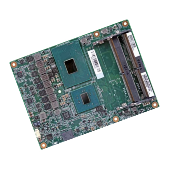
- Page 1 SH960-QM170/HM170 COM Express Basic Module User’s Manual A41410731 Chapter 1 Introduction www.dfi .com...
-
Page 2: Copyright
Product names or trademarks appearing in this manual are for identification purpose only and 2. Shielded interface cables must be used in order to comply with the emission limits. are the properties of the respective owners. COM Express Specification Reference PICMG COM Express Module Base Specification. ® http://www.picmg.org/ Chapter 1 Introduction www.dfi.com... -
Page 3: Table Of Contents
....................13 CPU Fan Connector..................13 COM Express Connectors ................14 COM Express Connectors Signal Discription ..........16 Standby Power LED ................32 Cooling Option .................... 32 Installing SH960-QM170/HM170 onto a Carrier Board ....33 Chapter 1 Introduction www.dfi .com... -
Page 4: About This Manual
To reduce the risk of electric shock: • Unplug the power cord before removing the system chassis cover for installation or servic- ing. After installation or servicing, cover the system chassis before plugging the power cord. Chapter 1 Introduction www.dfi.com... -
Page 5: About The Package
About the Package The package contains the following items. If any of these items are missing or damaged, please contact your dealer or sales representative for assistance. • One SH960 board • • One Cooler (Height: 36.58mm) Optional Items • COM332-B carrier board kit •... -
Page 6: Chapter 1 - Introduction
System Reset, Programmable via Software from 1 to 255 Seconds Intel ® Celeron ® Processor G3902E, Dual Core, 2M Cache, 1.6GHz, 25W Timer Interval Chipset Intel QM170 (SH960-QM170) ® Security Available Upon Request Intel HM170 (SH960-HM170) ® Memory Two 260-pin SODIMM up to 32GB Power... -
Page 7: Features
USB 1.1 (12Mb/s). USB 3.0 reduces the time required for data transmission, reduces power consumption, and is backward compatible with USB 2.0. It is a marked improvement in device transfer speeds between your computer and a wide range of simultaneously accessible external Plug and Play peripherals. Chapter 1 Introduction www.dfi.com... -
Page 8: Chapter 2 - Concept
Chapter 2 - Concept COM Express Module Standards The figure below shows the dimensions of the different types of COM Express modules. SH960-QM170/HM170 is a COM Express Basic module. The dimension is 95mm x 125mm. Common for all Form Factors Extended only... -
Page 9: Specification Comparison Table
Chapter 2 Specification Comparison Table The table below shows the COM Express standard specifications and the corresponding specifications supported on the SH960-QM170/HM170 module. Module Pin-out - Required and Optional Features A-B Connector. COM Express Module Base DFI SH960 COM Express Module Base... -
Page 10: Chapter 3 - Hardware Installation
Controller CORE CH7517 Standby Power LED Intel CPU fan DDI Port 3 (optional) LPC Bus PTN3460 QM170/HM170 Serial Port 0,1 CPU fan SLP/LID SH960-QM170: QM170 TPM 1.2 SH960-HM170: HM170 Embedded (optional) Controller Fan PWM/ Chrontel Intel TACH_IN IT8528E CH7517 I219LM C Bus USB 3.0 4x... -
Page 11: Mechanical Diagram
Chapter 3 Mechanical Diagram Heat Sink and Fan SH960-QM170/HM170 Module 91.00 87.00 150±5.0 19.00 70.00 36.00 30.20±0.1 4.00 45.41 11.46 0.00 4.00 4.00 76.00±0.1 41.00±0.10 0.00 2.50 14.00 Chapter 3 Hardware Installation www.dfi.com... -
Page 12: System Memory
Chapter 3 Installing the DIMM Module Important: Electrostatic discharge (ESD) can damage your board, processor, disk drives, add-in boards, and other components. Perform installation procedures at an ESD workstation Note: only. If such a station is not available, you can provide some ESD protection by wear- The system board used in the following illustrations may not resemble the actual one. -
Page 13: Connectors
BIOS Setting “PC Health Status” submenu in the Advanced menu of the BIOS will display the current speed of the cooling fan. Refer to chapter 4 of the manual for more information Clip Clip Chapter 3 Hardware Installation www.dfi.com... -
Page 14: Com Express Connectors
Connect the COM Express connectors (located on the solder side of the board) to the COM Express connectors on the carrier board. Refer to the “Installing SH960-QM170/HM170 onto a Carrier Board” section for more informa- tion. - Page 15 Revision 2.1 - Draft 0.92 / Copyright PICMG (file PICMG_COM_0_R2_1_D092.odt) DRAFT Version - Do Not Design To/Do Not Claim Compliance To/Do Not Distribute This Document DRAFT Version - Do Not Design To/Do Not Claim Compliance To/Do Not Distribute This Document Chapter 3 Hardware Installation www.dfi.com...
-
Page 16: Com Express Connectors Signal Discription
O SATA AC coupled on Module AC Coupling capacitor Serial ATA channel 0 Serial ATA or SAS Channel 0 transmit differential pair. Transmit output differential pair. Chapter 3 Hardware Installation www.dfi.com SATA0_TX- O SATA AC coupled on Module AC Coupling capacitor... - Page 17 PCI Express Differential Transmit Pairs 3 PCIe channel 3. Transmit Output differential pair. PCIE_TX3- AC Coupling capacitor PCIE_RX3+ Chapter 3 Hardware Installation www.dfi.com I PCIE AC coupled off Module PCI Express Differential Receiv e Pairs 3 PCIe channel 3. Receiv e Input differential pair.
- Page 18 PCIe channel 7. Receiv e Input differential pair. PCIE_RX7- PCIE_CLK_REF+ Reference clock output for all PCI Express and PCI Express Graphics PCIe Reference Clock for all COM Express PCIe lanes, and for O PCIE PCIE lanes. PEG lanes. PCIE_CLK_REF- Chapter 3 Hardware Installation www.dfi.com...
- Page 19 PCIe Reference Clock for all COM Express PCIe lanes, and for O PCIE PCIE lanes. PEG lanes. PEG_RX6+ PCIE_CLK_REF- I PCIE AC coupled off Module PCI Express Graphics receiv e differential pairs 6 PEG channel 6, Receiv e Input differential pair. Chapter 3 Hardware Installation www.dfi.com PEG_RX6-...
- Page 20 PCI Express Graphics transmit differential pairs 8 PCI Express Graphics transmit differential pairs 14 PEG channel 8, Transmit Output differential pair. PEG channel 14, Transmit Output differential pair. Chapter 3 Hardware Installation www.dfi.com PEG_TX8- PEG_TX14- AC Coupling capacitor AC Coupling capacitor...
- Page 21 PCI Express Graphics transmit differential pairs 8 PEG channel 8, Transmit Output differential pair. I/O USB 3.3V Suspend/3.3V USB differential pairs, channel 5 PEG_TX8- AC Coupling capacitor Chapter 3 Hardware Installation USB5- USB Port 5, data - or D- www.dfi.com...
- Page 22 USB Port 2, SuperSpeed TX + Additional transmit signal differential pairs for the SuperSpeed USB data LVDS Signals Descriptions O PCIE AC coupled on Module Chapter 3 Hardware Installation path. www.dfi.com USB_SSTX2- AC Coupling capacitor USB Port 2, SuperSpeed TX -...
- Page 23 USB Port 2, SuperSpeed TX + Additional transmit signal differential pairs for the SuperSpeed USB data O PCIE AC coupled on Module Chapter 3 Hardware Installation path. www.dfi.com Signal Pin# Pin Ty pe Pwr Rail /Tolerance SH960 PU/PD Module Base Specification R2.1 Description COM Express Carrier Design Guide R2.0 Description...
- Page 24 3.3V / 3.3V Horizontal sy nc output to VGA monitor Horizontal sy nc output to VGA monitor. Chapter 3 Hardware Installation LPC_AD3 www.dfi.com VGA_VSYNC O CMOS 3.3V / 3.3V Vertical sy nc output to VGA monitor Vertical sy nc output to VGA monitor.
- Page 25 DP1_AUX- for DP Half-duplex bi-directional AUX channel for services such as link configuration or maintenance and EDID access Chapter 3 Hardware Installation www.dfi.com DDI1_CTRLCLK_AUX- PU 2.2K to 3.3V/PU 100K DDI for SDVO: SDVO1_CTRLDATA (SDVO I2C data line - to set up SDVO...
- Page 26 3.3V with a 100k Ohm resistor to configure the AUX DP2_LANE1+ for DP / TMDS2_DATA1+ for HDMI or DVI DDI for Display Port: DP2_LANE 1 differential pairs Chapter 3 Hardware Installation www.dfi.com O PCIE AC coupled off Module pairs as DDC channels.
- Page 27 Receive Line for Serial Port 1 DDI2_PAIR1+ DP2_LANE1+ for DP / TMDS2_DATA1+ for HDMI or DVI DDI for Display Port: DP2_LANE 1 differential pairs Chapter 3 Hardware Installation www.dfi.com O PCIE AC coupled off Module DDI for HDMI/DVI: TMDS2_DATA lanes 1 differential pairs DDI2_PAIR1-...
- Page 28 Carrier Board as an indication that they should go into power-down mode. Chapter 3 Hardware Installation www.dfi.com Indicates system is in Suspend to RAM state. Active low output. An S3 Sleep control signal indicating that the system resides in S3 state...
- Page 29 Active low output indicating that the CPU has entered thermal shutdown. 'THRMTRIP#' goes active the system immediately transitions to the GPO0 S5 State (Soft Off). Chapter 3 Hardware Installation www.dfi.com GPO1 General purpose output pins. Upon a hardware reset, these outputs should O CMOS 3.3V / 3.3V...
- Page 30 Type 1 Module. To indicate the Module's pin-out type, the pins are Chapter 3 Hardware Installation pin out Type 2 www.dfi.com either not connected or strapped to ground on the Module. pin out Type 3 (no IDE) TYPE1#...
- Page 31 1-6. A Carrier can detect a R1.0 Module by the presence of 12V on this pin. R2.0 Module types 1-6 will no connect this pin. Type 10 Modules shall pull this pin to ground through a 47K resistor. Chapter 3 Hardware Installation www.dfi.com...
-
Page 32: Standby Power Led
Bottom View of the Heat Sink • “1” and “2” denote the locations of the thermal pads designed to contact the corresponding components that are on SH960-QM170/HM170. Important: Remove the plastic covering from the thermal pads prior to mounting the heat sink onto SH960-QM170/HM170. -
Page 33: Installing Sh960-Qm170/Hm170 Onto A Carrier Board
SH960-QM170/HM170 onto the carrier board of your choice. • To download COM332-B datasheet and manual 1. Grasping SH960-QM170/HM170 module by its edges, position it on top of the carrier board with its mounting holes aligned with the bolts on the carrier board. This helps align the COM Express connectors of the two boards to each other. - Page 34 Make sure to screw on the heatsink in the sequence as shown in the image below to Side View of the Heatsink, Module, and Carrier Board avoid seriously damaging the CPU. 4. Connect the heat sink and fan’s cable to the fan connector on SH960-QM170/HM170. Fan connector Chapter 3 Hardware Installation...
-
Page 35: Chapter 4 - Bios Setup
“Press DEL to run setup” will appear on the screen. If the message disappears before you respond, restart the system or press the “Reset” button. You may also restart the system by pressing the <Ctrl> <Alt> and <Del> keys simultaneously. Chapter 4 BIOS Setup www.dfi.com... -
Page 36: Insyde Bios Setup Utility
The time format is <hour>, <minute>, <second>. The time is based on the 24-hour military-time clock. For example, 1 p.m. is 13:00:00. Hour displays hours from 00 to 23. Minute displays minutes from 00 to 59. Second displays seconds from 00 to 59. Chapter 4 BIOS Setup www.dfi.com... - Page 37 S5 State The system appears to be off when power is re-applied after AC power loss. Turbo Mode This field is used to enable or disable processor turbo mode (requires EMTTM enabled too). AUTO means enabled, unless max turbo ration is bigger than 16 -SKL AO W/A. Chapter 4 BIOS Setup www.dfi.com...
- Page 38 Select SubMenu Save and Exit Note: Intenal Graphics VGA is transferred from DDI3 port interface. Keep IGFX enabled or disabled based on the setup options. Always Enabled PEG Enable or disable the PEG function. Chapter 4 BIOS Setup www.dfi.com...
- Page 39 PEG LinkWidth Disabled Select PEG Port LinkWidth: PEG 2*8 or PEG*16. HDA will be unconditionally disabled. LVDS Support Enabled HDA will be unconditionally enabled. Turn on/off LVDS. Auto HDA will be enabled if present, disabled otherwise. Chapter 4 BIOS Setup www.dfi.com...
- Page 40 Note: RST can support RAID 0/1/5/10 mode (5/10 mode needs at least three stor- ages) Serial ATA Port 0, 1, 2, and 3 This field is used to enable or disable the serial ATA port. Chapter 4 BIOS Setup www.dfi.com...
- Page 41 Save and Exit PCI Express Root Port This field is used to enable or disable the PCI Express Root Port. PCIe Speed Select the speed of the PCI Express Root Port: Auto, Gen1, Gen2 or Gen3. Chapter 4 BIOS Setup www.dfi.com...
- Page 42 ←/→ Select Item Enter Select SubMenu Save and Exit Serial Port 1 to Serial Port 2 Configure the settings to use the serial port. Disable No configuration Enable User configuration Auto EFI/OS chooses configuration Chapter 4 BIOS Setup www.dfi.com...
-
Page 43: Security
CPU ( 64 C/ 147 F Fan Speed SYS FAN 0 RPM CPU FAN 5158 RPM Help ↑/↓ Select Item F5/F6 Change Values Setup Defaults Exit ←/→ Select Item Enter Select SubMenu Save and Exit Chapter 4 BIOS Setup www.dfi.com... - Page 44 Change Values Setup Defaults Exit ←/→ Select Item Enter Select SubMenu Save and Exit Help ↑/↓ Select Item F5/F6 Change Values Setup Defaults Exit ←/→ Select Item Enter Select SubMenu Save and Exit Chapter 4 BIOS Setup www.dfi.com...
-
Page 45: Boot
Enable or disable the booting for USB boot devices. Enter New Password: Enter New Password Again: Help ↑/↓ Select Item F5/F6 Change Values Setup Defaults Exit ←/→ Select Item Enter Select SubMenu Save and Exit Chapter 4 BIOS Setup www.dfi.com... - Page 46 Change Values Setup Defaults Exit ←/→ Select Item Enter Select SubMenu Save and Exit Help ↑/↓ Select Item F5/F6 Change Values Setup Defaults Exit ←/→ Select Item Enter Select SubMenu Save and Exit Chapter 4 BIOS Setup www.dfi.com...
-
Page 47: Exit
Select this field and then press <Enter> to exit the system setup and save your changes. Load Optimal Defaults Select this field and then press <Enter> to load optimal defaults. Discard Changes Select this field and then press <Enter>to exit the system setup without saving your changes. Chapter 4 BIOS Setup www.dfi.com... -
Page 48: Updating The Bios
Copyright(c) 2012 - 2016, Insyde Software Corp. All Rights Reserved. Initializing Current BIOS Model name: SH960 New BIOS Model name: SH960 Current BIOS version: 65.05A New BIOS version: 65.05A Updating Block at FFFFF000h 100% 100% C:\SH960>_ Chapter 4 BIOS Setup www.dfi.com... -
Page 49: Chapter 5 - Supported Software
If after inserting the DVD, “Autorun” did not automatically start (which is, the Mainboard Utility DVD screen did not appear), please go directly to the root directory of the DVD and double- click “Setup”. Auto Run Page (For Windows 10) Chapter 5 Supported Software www.dfi.com... - Page 50 Intel chipset can be recognized and configured properly in the system. To install the utility, click “Intel Chipset Software Installation Utility” on the main menu. 1. Setup is ready to install the utility. Click “Next”. 2. Read the license agreement then click “Yes”. Chapter 5 Supported Software www.dfi.com...
- Page 51 Windows 8.1/ Windows 10 desktop appears. The “blank screen” period is the time Windows is testing the graphics performance. We recommend that you skip this process by disabling this function then click “Next”. 2. Read the license agreement then click “Yes”. Chapter 5 Supported Software www.dfi.com...
- Page 52 Restarting the system will allow the new software installation to take effect. 5. Click “Yes, I want to restart this computer now” then click “Finish”. Restarting the system will allow the new software installation to take effect. Chapter 5 Supported Software www.dfi.com...
- Page 53 1. Setup is ready to install the driver. Click “Next”. 5. After completing installa- tion, click “Finish”. 2. Click “I accept the terms in the license agreement” then click “Next”. 3. Select the program featuers you want installed then click “Next”. Chapter 5 Supported Software www.dfi.com...
- Page 54 3. Click “Restart Now“ to restart your computer when the installation is complete. To install the driver, click “Kernel Mode Driver Framework” on the main menu. 1. Click “Yes“ to install the update. 2. The update is installed now. Chapter 5 Supported Software www.dfi.com...
- Page 55 1. Setup is ready to install the driver. Click “Next”. 4. Please wait while the prod- uct is being installed. 2. Read the license agreement then click “Next”. 5. After completing installa- tion, click “Finish”. Chapter 5 Supported Software www.dfi.com...
- Page 56 1. Setup is ready to install the driver. 4. The wizard is ready to begin installation. Click “Install”. 2. Click “Next” to continue. 5. Please wait while the program features are being installed. Chapter 5 Supported Software www.dfi.com...
- Page 57 Chapter 5 6. After completing installa- The HW Utility icon will appear on the desktop. Double-click the icon to open the utility. tion, click “Finish”. Information HW Health Chapter 5 Supported Software www.dfi.com...
- Page 58 Chapter 5 Watchdog Backlight Chapter 5 Supported Software www.dfi.com...
- Page 59 1. Setup is ready to install the driver. Click “Next”. 4. Setup is currently installing the driver. After installation has com- pleted, click “Next”. 2. Read the license agreement then click “Yes”. 5. After completing installation, click “Finish”. Chapter 5 Supported Software www.dfi.com...
- Page 60 To install the driver, click “Microsoft Framework 4.5.2” on the main menu. 1. Setup is now extracting files. 4. Click “Finish”. 2. Read the license agreement care- fully. Click “I have read and accept the terms of the License Agree ment” then click “Install”. Chapter 5 Supported Software www.dfi.com...
- Page 61 To install the driver, click “Intel Rapid Storage Technology” on the main menu. Please refer to Chapter 6 for more information. 2. The setup program is now ready to install the utility. Click “Next”. 3. Click “I accept the terms in the license agreement” and then click “Next”. Chapter 5 Supported Software www.dfi.com...
- Page 62 Visual C++ package prior to installing the utility. Click “Install”. 5. Select a setup type and then click 8. The setup program is currently “Next”. installing the Microsoft Visual C++ package. 9. Click “Finish”. 6. Click “Install”. Chapter 5 Supported Software www.dfi.com...
- Page 63 To install the reader, click “Adobe Acrobat Reader 9.3” on the main menu. 1. Click Next to install or click Change Destination Folder to select another folder. 2. Click “Install” to begin instal- lation. 3. Click “Finish” to exit installation. Chapter 5 Supported Software www.dfi.com...
-
Page 64: Chapter 6 - Raid
Single Drive Failure Disk mirroring Block-level data striping with RAID 5 Single Drive Failure distributed parity 1 Disk Per Mirrored Combination of RAID 0 (data striping) RAID 10 Stripe (not same mirror) and RAID 1 (mirroring) Chapter 6 RAID www.dfi.com... -
Page 65: Create A Raid Volume
These steps are cited from the Intel Suppot site, “Set Up a System with Intel ment and click “I accept ® ® Matrix RAID Technology” (Article ID: 000005789). the terms in the License http://www.intel.com/content/www/us/en/support/boards-and-kits/000005789.htm Agreement.“ Then, click “Next”. Chapter 6 RAID www.dfi.com... - Page 66 “Finish”. “Next”. 6. Click “Next” to install to the default folder or click change to choose another destination folder. 7. Confirm the installation and click “Next”. Chapter 6 RAID www.dfi.com...
-
Page 67: Chapter 7 - Intel Amt Settings
Intel AMT Support <Enabled> ways enabled. This option just controls the BIOS extension execution. Help ↑/↓ Select Item F5/F6 Change Values Setup Defaults Exit ←/→ Select Item Enter Select SubMenu Save and Exit Chapter 7 Intel AMT Settings www.dfi.com... -
Page 68: Extension (Mebx) Screen
MEBx Exit Help ↑/↓ Select Item F5/F6 Change Values Setup Defaults Exit ←/→ Select Item Enter Select SubMenu Save and Exit Intel(R) ME Password [↑↓] = Move Highlight [Enter] = Select Entry [Esc]= Exit Chapter 7 Intel AMT Settings www.dfi.com... - Page 69 Intel(R) Management Engine BIOS Extension v11.0.0.0005/Intel(R) ME v11.0.0.1197 Copyright(C) 2003-15 Intel Corporation. All Rights Reserved. MAIN MENU > Intel (R) ME General Settings > Intel (R) AMT Configuration MEBx Exit [↑↓] = Move Highlight [Enter] = Select Entry [Esc]= Exit Chapter 7 Intel AMT Settings www.dfi.com...
- Page 70 > User Consent Password Policy <Anytime> > Network Setup Activate Netwok Access Unconfigure Network Access <Full Unprovision> > Remote Setup And Configuration > Power Control [↑↓] = Move Highlight [Enter] = Select Entry [Esc]= Exit Chapter 7 Intel AMT Settings www.dfi.com...
- Page 71 <Full Unprovi- Disabled sion> Enabled > Remote Setup And Configuration > Power Control [↑↓] = Move Highlight [Enter] = Select Entry [Esc]= Exit [↑↓] = Move Highlight [Enter] = Complete Entry [Esc]= Discard Changes Chapter 7 Intel AMT Settings www.dfi.com...
- Page 72 < Enabled> Storage Redirection <Enabled> KVM Feature Selection <Enabled> NONE Disabled Enabled [↑↓] = Move Highlight [Enter] = Complete Entry [Esc]= Discard Changes [↑↓] = Move Highlight [Enter] = Complete Entry [Esc]= Discard Changes Chapter 7 Intel AMT Settings www.dfi.com...
- Page 73 > Remote Setup And Configuration > Power Control Default Password Only During Step And Configuration Anytime [↑↓] = Move Highlight [Enter] = Select Entry [Esc]= Exit [↑↓] = Move Highlight [Enter] = Complete Entry [Esc]= Discard Changes Chapter 7 Intel AMT Settings www.dfi.com...
- Page 74 Shared/ Dedicated FQDN <Shared> Dynamic DNS Update <Disabled> Dynamic DNS Update <Disabled> Computer Domain Name Disabled Enabled [Enter] = Complete Entry [Esc]= Discard Changes [↑↓] = Move Highlight [Enter] = Complete Entry [Esc]= Discard Changes Chapter 7 Intel AMT Settings www.dfi.com...
- Page 75 Intel(R) Management Engine BIOS Extension v11.0.0.0005/Intel(R) ME v11.0.0.1197 Copyright(C) 2003-15 Intel Corporation. All Rights Reserved. WIRED LAN IPV4 CONFIGURATION DHCP Mode <Enabled> Disabled Enabled [↑↓] = Move Highlight [Enter] = Complete Entry [Esc]= Discard Changes Chapter 7 Intel AMT Settings www.dfi.com...
- Page 76 > Power Control Full Unprovision and opens the ME network interface Continue: (Y/N) [↑↓] = Move Highlight [Enter] = Select Entry [Esc]= Exit [↑↓] = Move Highlight [Enter] = Complete Entry [Esc]= Discard Changes Chapter 7 Intel AMT Settings www.dfi.com...
- Page 77 Provisioning Server FQDN > RCFG > RCFG > TLS PKI > TLS PKI Provisioning server address Provisioning Mode:PKI [Enter] = Complete Entry [Esc]= Discard Changes [↑↓] = Move Highlight [Enter] = Select Entry [Esc]= Exit Chapter 7 Intel AMT Settings www.dfi.com...
- Page 78 > Manage Hashes This will activate Remote Condigura- Disabled tion. Continue: (Y/N) Enabled [↑↓] = Move Highlight [Enter] = Complete Entry [Esc]= Discard Changes [↑↓] = Move Highlight [Enter] = Select Entry [Esc]= Exit Chapter 7 Intel AMT Settings www.dfi.com...
- Page 79 Activate Netwok Access Unconfigure Network Access <Full Unprovision> > Remote Setup And Configuration > Power Control [↑↓] = Move Highlight [Enter] = Select Entry [Esc]= Exit [↑↓] = Move Highlight [Enter] = Select Entry [Esc]= Exit Chapter 7 Intel AMT Settings www.dfi.com...
- Page 80 This configurations are effective only after AMT provisioning has started Intel (R) ME ON in Host Sleep States <Mobile: ON in S0, ME Wake in S3, S4-5 (AC only)> Idle Timeout 65535 Timeout Value (1-65535) 65535 <ENTER> = Complete Entry [ESC]= Discard Changes Chapter 7 Intel AMT Settings www.dfi.com...
-
Page 81: Appendix A - Troubleshooting
AC outlet. If necessary, try another outlet. 3. Check that the video input cable is properly attached to the monitor and the system’s display adapter. 4. Adjust the brightness of the display by turning the monitor’s brightness control knob Appendix A Troubleshooting www.dfi.com... - Page 82 Nothing happens when a key on the keyboard was pressed. 1. Make sure the keyboard is properly connected. 2. Make sure there are no objects resting on the keyboard and that no keys are pressed dur- ing the booting process. Appendix A Troubleshooting www.dfi.com...
-
Page 83: Appendix B - Insyde Bios Standard Status Post Code
Prepare to Boot to Legacy OS BDS_EXIT_BOOT_SERVICES Send END of POST Message to ME via HECI PostBDS Phase 8-Bit POST Code Values Functionality Name POST Code Value Description Appendix B Insyde BIOS Standard Status POST Code www.dfi.com POST_BDS_NO_BOOT_DEVICE No Boot Device...
Need help?
Do you have a question about the SH960-QM170 and is the answer not in the manual?
Questions and answers