Table of Contents
Advertisement
Quick Links
Advertisement
Table of Contents

Related Manuals for DFI EHL9A2


Summary of Contents for DFI EHL9A2
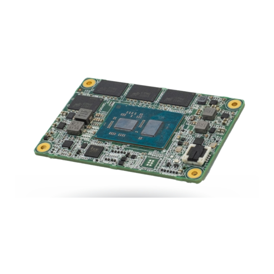
- Page 1 EHL9A2 COM Express Mini Module User’s Manual © February 14, 2023 DFI Inc.
- Page 2 COM Express Specification Reference • Shielded interface cables must be used in order to comply with the emission limits. PICMG® COM Express® Module Base Specification. http://www.picmg.org/ User's Manual | EHL9A2...
-
Page 3: Table Of Contents
Pin List for Pin-Out Type 10 ..................22 Module Feature Fill Order ....................24 Feature Fill Order ......................24 Cooling Option ........................25 Heat Sink ........................25 Installing EHL9A2 onto a Carrier Board ................25 Installing the COM Express Debug Card ................26 COMe-DEBUG .........................27 Chapter 4 - BIOS Setup .......................29 Main ............................30 Advanced ..........................30... - Page 4 • To reduce the risk of electric shock, unplug the power cord before removing the sys- tem chassis cover for installation or servicing. After installation or servicing, cover the system chassis before plugging the power cord. User's Manual | EHL9A2...
- Page 5 • Storage devices such as hard disk drive, etc. You will also need external system peripherals you intend to use which will normally include at least a keyboard, a mouse and a video display monitor. User's Manual | EHL9A2...
-
Page 6: Chapter 1 - Introduction
1 x Intel I225IT / I225-LM (10/100/1000Mbps/2.5Gbps) ® 2 x USB 3.1 Gen2 8 x USB 2.0 SATA 2 x SATA 3.0 (up to 6Gb/s) eMMC 1 x 8GB/16GB/32GB/64GB*/128GB eMMC 5.1 (available upon request) 1 x 8-bit DIO User's Manual | EHL9A2... - Page 7 Humidity Operating: 5 to 90% RH Storage: 5 to 90% RH MTBF MECHANICAL Dimensions COM Express® Mini 84mm (3.3") x 55mm (2.16") Compliance PICMG COM Express® R3.0, Type 10 STANDARDS AND CER- Certification CE, FCC TIFICATIONS User's Manual | EHL9A2...
-
Page 8: Block Diagram
Chapter 1 INTRODUCTION X Block Diagram User's Manual | EHL9A2... -
Page 9: Chapter 2 - Concept
Chapter 2 - Concept X COM Express Module Standards The figure below shows the dimensions of the different types of COM Express modules. EHL9A2 is a COM Express Mini. The dimension is 84mm x 55mm. Common for all Form Factors Extended only... -
Page 10: Chapter 3 - Hardware Installation
If a wrist strap is unavailable, establish and maintain contact with the system chassis throughout any procedures requiring ESD protection. User's Manual | EHL9A2... -
Page 11: Connector
EHL9A2 module. Type 10 Modules support a single 24 bit The COM Express connector is used to interface the EHL9A2 COM Express board to a carrier LVDS panel interface, a single DDI and an eDP overlayed on LVDS Channel A.Two of the 8 board. - Page 12 1 / 1 Power Good 1 / 1 VCC_5V_SBY 4 / 4 Contacts Sleep Input 0 / 1 Lid Input 0 / 1 Carrier Board Fan 0 / 1 Control • Power VCC_12V Contacts 12 / 12 User's Manual | EHL9A2...
-
Page 13: Com Express Connector Signal Description
AC coupled on Module AC Coupling capacitor Serial ATA activity LED. Open collector output pin driven during (S)ATA_ACT# I/O CMOS 3.3V / 3.3V PU 10K to 3.3V Serial ATA (activity indicator), active low. SATA command activity. User's Manual | EHL9A2... -
Page 14: Com Express Connector Signal Description
An open drain driver from a USB current monitor on the Carrier Board Do not pull up these lines to 3.3V on the Carrier Board – this shall be may drive this line low. done on the Module. Do not pull this line high on the Carrier Board. User's Manual | EHL9A2... -
Page 15: Com Express Connector Signal Description
LVDS channel A differential signal pair 3 LVDS_A3- Module LVDS LVDS_A_CK+/eDP_TX3+ LVDS Channel A differential clock LVDS channel A differential clock pair O LVDS EDP: AC coupled off eDP: eDP differential pairs eDP lane 3, TX± differential pair LVDS_A_CK-/eDP_TX3- Module User's Manual | EHL9A2... -
Page 16: Com Express Connector Signal Description
I CMOS 3.3V Suspend/3.3V Data in to Module from Carrier SPI Data in to Module from Carrier SPI SPI_MOSI O CMOS 3.3V Suspend/3.3V Data out from Module to Carrier SPI Data out from Module to Carrier SPI User's Manual | EHL9A2... -
Page 17: Com Express Connector Signal Description
(S/W IC between (DP AUX- function if DDI0_DDC_AUX_SEL is no connect) Rpu/PCH) DDI0_CTRLCLK_AUX- AC coupled on Module DP1_AUX- for DP PCIE Half-duplex bi-directional AUX channel for services such as link configuration or maintenance and EDID access User's Manual | EHL9A2... -
Page 18: Com Express Connector Signal Description
PD 100KΩ to GND. TPM chip has an internal pull down. This signal is used to indicate Physical CMOS an internal pull down. Thissignal is used to indicate Physical Presence to the TPM. Presence to the TPM. User's Manual | EHL9A2... -
Page 19: Com Express Connector Signal Description
Power and System Management Signals Descriptions Pwr Rail Signal Pin# Pin Type EHL9A2 PU/PD Module Base Specification R3.0 Description COM Express Carrier Design Guide R2.0 Description /Tolerance PU 10KΩ to 3.3V A falling edge creates a power button event. Power button events can be used to bring a system out of S5 soft off Power button low active signal used to wake up the system from S5 state (soft off). -
Page 20: Com Express Connector Signal Description
SDIO: SDIO Data lines. These signals operate in push-pull mode. Maps to GPI[0:3]. usage. The signals are pulled up by the Module. I CMOS / GPI2/SD_DATA2 PU 47KΩ to 3.3V IO CMOS I CMOS / GPI3/SD_DATA3 PU 47KΩ to 3.3V IO CMOS User's Manual | EHL9A2... -
Page 21: Com Express Connector Signal Description
VCC_12V pins. In R2.0 this pin is defined as a no connect for types 1-6. A Carrier can detect a R1.0 12V Pin-out R1.0 Module by the presence of 12V on this pin. R2.0 Module types 1-6 will no connect this pin. Type 10 Modules shall pull this pin to ground through a 47K resistor. User's Manual | EHL9A2... -
Page 22: Com Express Pin Assignments
PU 10K to 3.3VSB GBE0_SDP SYS_RESET# SATA0_RX+ SATA1_RX+ LPC_SERIRQ CB_RESET# SATA0_RX- SATA1_RX- GND(FIXED) GND(FIXED) GND(FIXED) GND(FIXED) RSVD RSVD USB_SSRX0- USB_SSTX0- RSVD RSVD USB_SSRX0+ USB_SSTX0+ GPI0/SD_DATA0** GPO1/SD_CMD** SUS_S5# PWR_OK RSVD RSVD USB_SSRX1- USB_SSTX1- RSVD RSVD USB_SSRX1+ USB_SSTX1+ User's Manual | EHL9A2... - Page 23 2. ** SD (in place of GPIO) is BOM option supported by project basis. LVDS_I2C_CK/ LVDS_BKLT_TRL/ eDP_AUX+** eDP_BKLT_CTRL** 3. EHL9A2 (Mini module) allows wide range input voltage wtih 4.75V to 20V from LVDS_I2C_DAT/ VCC_5V_SBY VCC_12V power pins. eDP_AUX-** 4. For PCIe device down components on the carrier board, please use and place...
-
Page 24: Module Feature Fill Order
USB Channel 7 only USB 2.0 (Option for static changing, select the USB2.0 port client port in the BIOS Client setup and reset the BIOS) USB 3.0 USB channel 0 SuperSpeed USB channels 0,1 DDI 1 User's Manual | EHL9A2... -
Page 25: Cooling Option
COM Express connector on the carrier board. 1. Grasp EHL9A2 by its edges and position it on top of the carrier board with its COM Express connector aligned with the COM Express connector on the carrier board. This will also help align the mountings holes of EHL9A2 with the standoffs on the carrier board. -
Page 26: Installing The Com Express Debug Card
3. Align the mounting holes of the heatsink with the mounting holes of the module. Use the provided mounting screws to install the heat sink onto the module. COM Express Connector Note: The system board used in the following illustrations may not resemble the actual board. These illustrations are for reference only. User's Manual | EHL9A2... -
Page 27: Come-Debug
COM Express COM Express Type Display Signal Display COM Express Power/Reset/ Power Display Bolts Sleep/LID control 4. Use the provided bolts to fix the COMe-LINK2 debug card onto the carrier board. Cable COMe-DEBUG COMe-LINK2 Bolts COMe-DEBUG COMe-LINK2 User's Manual | EHL9A2... - Page 28 5. Grasp the COM Express Mini module by its edges to press it down on the top of the COMe-LINK2 debug card. COM Express Mini Module T6 transfer T10 card COMe-LINK2 6. Then, grasp the heat sink by its edges and position it down firmly on the top of the COM Express Mini module. User's Manual | EHL9A2...
-
Page 29: Chapter 4 - Bios Setup
“Press DEL to run setup” will appear on the screen. If the message that field and press <Enter>. disappears before you respond, restart the system or press the “Reset” button. You may also restart the system by pressing the <Ctrl> <Alt> and <Del> keys simultaneously. User's Manual | EHL9A2... -
Page 30: Main
The time format is <hour>, <minute>, <second>. The time is based on the 24-hour military- time clock. For example, 1 p.m. is 13:00:00. Hour displays hours from 00 to 23. Minute dis- plays minutes from 00 to 59. Second displays seconds from 00 to 59. User's Manual | EHL9A2... -
Page 31: Rc Acpi Configuration
S0 State The system automatically powers on after power failure. • S5 State The system enter soft-off state after power failure. Power-on signal input is required to power up the system. • Last State The system returns to the last state right before power failure. User's Manual | EHL9A2... -
Page 32: Power & Performance
After it is enabled in the BIOS, EIST features can then be enabled via the operating system’s power management. C states Enable or disable CPU Power Management. It allows CPU to enter "C states" when it’s idle and nothing is executing. User's Manual | EHL9A2... -
Page 33: Intel(R) Time Coordinated Computing
Enable or Disable Intel(R) TCC Mode. When enabled, this will modify system settings to im- prove real-time performance. The full list of settings and their current state are displayed below when Intel(R) TCC mode is enabled. User's Manual | EHL9A2... -
Page 34: Trusted Computing
"Security Device Support" is disabled. LCD Panel Color Depth Select the color depth of the LCD Panel — 18 Bit, 24 Bit. Backlight Type Select the inverter polarity and brightness control — Normal+PWM Mode, Normal+DC Mode. User's Manual | EHL9A2... -
Page 35: Pc Health Status
Chapter 4 BIOS SETTINGS Advanced Advanced PC Health Status DFI WDT Configuration Watchdog Timer Enable/Disable Watchdog Timer. Lists voltage, termperature, and fan speed. User's Manual | EHL9A2... -
Page 36: It8528 Super Io Configuration
BIOS SETTINGS Advanced Advanced IT8528 Super IO Configuration IT8528 Super IO Configuration ► Serial Port 1, 2 Configuration Serial Port Configuration Set Parameters of Serial Ports. See next page. Serial Port Enable or disable serial port. User's Manual | EHL9A2... -
Page 37: Serial Port Console Redirection
Select serial port transmission speed: 9600, 19200, 38400, 57600 or 115200. Data Bits Select data bits: 7 bits or 8 bits. Parity Select parity bits: None, Even, Odd, Mark or Space. Stop Bits Select stop bits: 1 bit or 2 bits. User's Manual | EHL9A2... -
Page 38: Usb Configuration
Set the wait time in seconds to press ESC key to abort the PXE boot. Use either +/- or nu- meric keys to set the value. Media detect count Set the number of times the presence of media will be checked. Use either +/- or numeric keys to set the value. User's Manual | EHL9A2... -
Page 39: Chipset
Chapter 4 Chapter 3 BIOS SETTINGS BIOS SETTINGS X Chipset Chipset System Agent (SA) Configuration User's Manual | EHL9A2... -
Page 40: System Agent (Sa) Configuration ► Memory Configuration
Keep IGFX "Enabled" or "Disabled" based on the setup options, or select "Auto" for auto-detec- tion. 0: Functional Mode protects requests based on the address range, 1: Makes all requests non protected and ignore range checks, 2: Makes all requests protected and ignore range checks User's Manual | EHL9A2... -
Page 41: Pch-Io Configuration
Enable or disable the PCI Express Root Port. The following fields are only available when the PCIe root port is enabled. PCIe Express Root Port 1,2,3,4 Control the PCI Express Root Port. PCIe Speed Configure PCIe speed. User's Manual | EHL9A2... -
Page 42: Pch-Io Configuration ► Sata Configuration
The mode selection determines how the SATA controller(s) operates. • Enabled HDA will be unconditionally enabled. • AHCI This option allows the Serial ATA controller(s) to use AHCI (Advanced Host Controller Interface). Ports Enable or disable the Serial ATA ports. User's Manual | EHL9A2... -
Page 43: Security
Clear the database from the NVRAM, including all the keys and signatures installed in the Key Management menu. Press Enter and a prompt will show up for you to confirm. Key Management Enables expert users to modify Secure Boot Policy variables without full authentication. User's Manual | EHL9A2... -
Page 44: Boot
Select this option to save BIOS configuration settings to a USB flash device. ► Restore Setting from file This field will appear only when a USB flash device is detected. Select this field to restore set- ting from the USB flash device. User's Manual | EHL9A2... -
Page 45: Updating The Bios
MAC address should be burned or not. c. After updating unique MAC Address from manufacturing, NVM will be protected immediately after power cycle. Users cannot update NVM or MAC address. User's Manual | EHL9A2...
Need help?
Do you have a question about the EHL9A2 and is the answer not in the manual?
Questions and answers