
Related Manuals for DFI SU968


Summary of Contents for DFI SU968
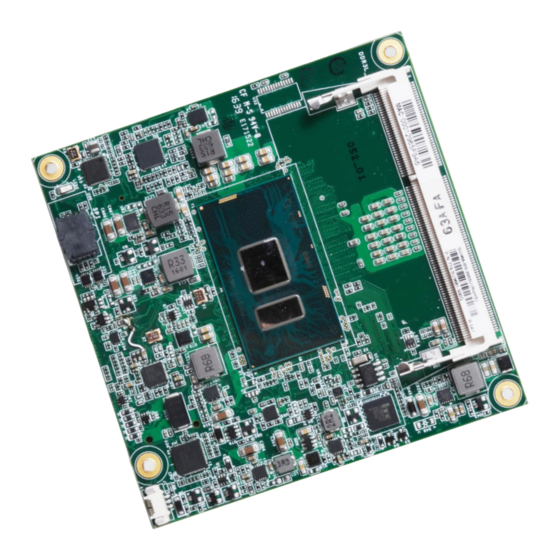
- Page 1 SU968 COM Express Compact Module User’s Manual A41300702 Chapter 1 Introduction www.dfi.com...
- Page 2 Product names or trademarks appearing in this manual are for identification purpose only and 2. Shielded interface cables must be used in order to comply with the emission limits. are the properties of the respective owners. COM Express Specification Reference PICMG COM Express Module Base Specification. ® http://www.picmg.org/ Chapter 1 Introduction www.dfi.com...
-
Page 3: Table Of Contents
COM Express Connectors Signals and Descriptions ....... 15 Standby Power LED ............... 22 Cooling Option ............... 22 Installing SU968 onto a Carrier Board ........23 Installing the COM Express Debug Card ........25 Chapter 4 - BIOS Setup ......27 Overview ................ -
Page 4: Specifications ...........................................................................6
To reduce the risk of electric shock: • Unplug the power cord before removing the system chassis cover for installation or servic- ing. After installation or servicing, cover the system chassis before plugging the power cord. Chapter 1 Introduction www.dfi.com... - Page 5 About the Package The package contains the following items. If any of these items are missing or damaged, please contact your dealer or sales representative for assistance. • One SU968 board • One DVD • One Heat Sink (Height: 23.8mm) Optional Items •...
-
Page 6: Chapter 1 - Introduction
(only Core i7/i5 supports iAMT) 4 x USB 3.0 8 x USB 2.0 SATA 3 x SATA 3.0 (up to 6Gb/s) (Core i7/i5) 2 x SATA 3.0 (up to 6Gb/s) (Celeron) RAID 0/1/5/10 (Core i7/i5 ) 1 x 8-bit DIO Chapter 1 Introduction www.dfi.com... -
Page 7: Features
USB 1.1 (12Mb/s). USB 3.0 reduces the time required for data transmission, reduces power consumption, and is backward compatible with USB 2.0. It is a marked improvement in device transfer speeds between your computer and a wide range of simultaneously accessible external Plug and Play peripherals. Chapter 1 Introduction www.dfi.com... -
Page 8: Chapter 2 - Concept
Chapter 2 - Concept COM Express Module Standards The figure below shows the dimensions of the different types of COM Express modules. SU968 is a COM Express Compact module. The dimension is 95mm x 95mm. Common for all Form Factors Extended only... -
Page 9: Specification Comparison Table
Chapter 2 Specification Comparison Table The table below shows the COM Express standard specifications and the corresponding specifications supported on the SU968 module. COM Express Module Base DFI SU968 COM Express Module Base DFI SU968 Specification Type 6 Type 6... -
Page 10: Chapter 3 - Hardware Installation
Power LED PCIe x1 DDR3L_2 SODIMM Intel ® GLAN PCIe x1 (2 x1) I219LM USB 2.0 8x SATA 3.0 3x SPI Bus Bottom View SPI Flash D110 COM Express connector C110 B110 COM Express connector A110 Chapter 3 Hardware Installation www.dfi.com... -
Page 11: Mechanical Diagram
Chapter 3 Mechanical Diagram SU968 Module Heat Sink Top View 46.64 Bottom View Chapter 3 Hardware Installation www.dfi.com... -
Page 12: System Memory
Power-off the PC then unplug the power cord prior to installing any devices. Failure to do so will cause severe damage to the board and components. DDR3L_1 SODIMM Bottom View Standby Power LED Top View Chapter 3 Hardware Installation www.dfi.com... -
Page 13: Connectors
Chapter 3 Connectors COM Express Connectors The COM Express connectors are used to interface the SU968 COM Express board to a carrier CPU Fan Connector board. Connect the COM Express connectors (located on the solder side of the board) to the COM Express connectors on the carrier board. -
Page 14: Com Express Connectors
C109 VCC_12V C109 VCC_12V D109 VCC_12V D109 VCC_12V PCIE_TX4+ PCIE_TX4+ PCIE_RX4+ PCIE_RX4+ A110 GND (FIXED) A110 GND (FIXED) B110 GND (FIXED) B110 GND (FIXED) C110 GND (FIXED) C110 GND (FIXED) D110 GND (FIXED) D110 GND (FIXED) Chapter 3 Hardware Installation www.dfi.com... -
Page 15: Com Express Connectors Signals And Descriptions
I/O Bi-directional input / output signal OD Open drain output AC97/HDA Signals and Descriptions Signal Pin# Module Pin Type Pwr Rail /Tolerance SU968 Carrier Board Description AC/HAD_RST# O CMOS 3.3V Suspend/3.3V Connect to CODEC pin 11 RESET# Reset output to CODEC, active low. - Page 16 Chapter 3 PCI Express Lanes Signals and Descriptions Signal Pin# Module Pin Type Pwr Rail /Tolerance SU968 Carrier Board Description PCIE_TX0+ AC Coupling capacitor O PCIE AC coupled on Module Connect to PCIE device or slot PCI Express Differential Transmit Pairs 0...
- Page 17 I PCIE AC coupled off Module PCI Express Graphics receive differential pairs 9 Signal PEG_RX9- Pin# Module Pin Type Pwr Rail /Tolerance SU968 Carrier Board Description PEG_TX0+ PEG_TX10+ O PCIE AC coupled on Module PCI Express Graphics transmit differential pairs 10...
- Page 18 I/O OD CMOS 3.3V / 3.3V HDMI/DVI I2C CTRLCLK if DDI2_DDC_AUX_SEL is pulled high Signal Pin# Module Pin Type Pwr Rail /Tolerance SU968 Carrier Board Description DDI1_PAIR0+/SDVO1_RED+ PU 100K to 3.3V Connect AC Coupling Capacitors 0.1uF to Device O PCIE...
- Page 19 Additional transmit signal differential pairs for the SuperSpeed USB data path. USB_SSTX2- Signal Pin# Module Pin Type Pwr Rail /Tolerance AC Coupling capacitor SU968 connector Carrier Board Description USB_SSRX2+ USB0+ Connect 90Ω @100MHz Common Choke in series and ESD suppressors to GND to USB Connect 90Ω...
- Page 20 Chapter 3 VGA Signals and Descriptions Signal Pin# Module Pin Type Pwr Rail /Tolerance SU968 Carrier Board Description VGA_RED O Analog Analog PD 150 to GND PD 150R,connect to VGA connector with EMI filter & ESD protect component. Red for monitor. Analog output PD 150R,connect to VGA connector with EMI filter &...
- Page 21 ACPI modes. Signal Pin# Module Pin Type Pwr Rail /Tolerance SU968 Carrier Board Description LID switch. Low active signal used by the ACPI operating system for a LID switch. A falling edge creates a power button event. Power button events can...
-
Page 22: Standby Power Led
Bottom View of the Heat Sink • “1” denotes the location of the thermal pad designed to contact the corresponding components that are on the SU968. Important: Remove the plastic covering from the thermal pads prior to mounting the heat sink onto the SU968. -
Page 23: Installing Su968 Onto A Carrier Board
3. Press SU968 down firmly to seat it in the COM Express connectors of the carrier board. Pressing points 2. Grasp SU968 by its edges and position it on top of the carrier board with the mounting holes of SU968 aligning with the standoffs on the carrier board. This will also align the COM Express connectors of the two boards to each other. - Page 24 4. Verify that SU968 is firmly seated in the COM Express connectors of the carrier board. Carrier board SU968 5. Install a heat sink onto the SU968 with the carrier board. The photo below shows the heat sink installed on SU968. Chapter 3 Hardware Installation www.dfi.com...
-
Page 25: Installing The Com Express Debug Card
COM Express modules. COMe-LINK1 COMe-LINK1/2 Connector COMe-DEBUG Connector COM Express COM Express Type Display Signal Display COM Express Power/Reset/ Power Display Sleep/LID control COM Express Connectors Cable Top view COMe-DEBUG COMe-LINK1 COM Express Connectors Bottom view Chapter 3 Hardware Installation www.dfi.com... - Page 26 3. Use the provided screws to fix the COMe-LINK1 debug card onto the carrier board. Screws COMe-LINK1 Carrier Board COMe-DEBUG 4. Then use the instructions from the previous section to install SU968 and heat sink on the top of the COMe-LINK1 debug card. BW968 COMe-LINK1 Carrier Board...
-
Page 27: Chapter 4 - Bios Setup
“Reset” button. You may also additional options are available for that field. To display the submenu, move the highlight to restart the system by pressing the <Ctrl> <Alt> and <Del> keys simultaneously. that field and press <Enter>. Chapter 4 BIOS Setup www.dfi.com... -
Page 28: Insyde Bios Setup Utility
Main Advanced Security Boot Exit This is the help for the Project Name SU968 hour, minute, second BIOS Version 68.16A field. Valid range is from 0 to 23, 0 to 59, 0 to 59. Processor Type Intel(R) Celeron (R) CPU 3599U @2.00 GHz InsydeH20 Setup Utility Rev. - Page 29 (G3 state). the limits of TDP. S0 State Power on the system when power is re-applied after AC power loss. S5 State The system appears to be off when power is re-applied after AC power loss. Chapter 4 BIOS Setup www.dfi.com...
- Page 30 <1280x1024> Backlight Type Normal +PWM Mode Normal +DC Mode Invert +PWM Mode Invert +DC Mode Help ↑/↓ Select Item F5/F6 Change Values Setup Defaults Exit ←/→ Select Item Enter Select SubMenu Save and Exit Chapter 4 BIOS Setup www.dfi.com...
- Page 31 Select Item Enter Select SubMenu Save and Exit The high-definition audio will be unconditionally disabled. Enabled The high-definition audio will be unconditionally enabled. Auto The high-definition audio will be enabled if present and disabled otherwise. Chapter 4 BIOS Setup www.dfi.com...
- Page 32 This option allows you to create RAID or Intel Matrix Storage configurations on Serial ATA devices. Serial ATA Port 0, 1, 2, and 3 This field is used to enable or disable each serial ATA port. Chapter 4 BIOS Setup www.dfi.com...
- Page 33 Save and Exit PCI Express Root Port This field is used to enable or disable the PCI Express Root Port. PCIe Speed Select the speed of the PCI Express Root Port: Auto, Gen1, Gen2 or Gen3. Chapter 4 BIOS Setup www.dfi.com...
- Page 34 COM Port 1 and COM Port 2 Me Fw Image Re-Flash Configure the settings of the serial ports. Enable or disable flashing of the Intel ME region. ® Disable Disable the serial port. Enable Enable the serial port. Chapter 4 BIOS Setup www.dfi.com...
-
Page 35: Security
CPU ( 82 C/ 179 F Fan Speed SYS FAN 0 RPM CPU FAN 4956 RPM Help ↑/↓ Select Item F5/F6 Change Values Setup Defaults Exit ←/→ Select Item Enter Select SubMenu Save and Exit Chapter 4 BIOS Setup www.dfi.com... -
Page 36: Boot
Enter New Password Again: How to clear HDD password: only press “Enter” when set new password. Help ↑/↓ Select Item F5/F6 Change Values Setup Defaults Exit ←/→ Select Item Enter Select SubMenu Save and Exit Chapter 4 BIOS Setup www.dfi.com... - Page 37 Enable or disable the booting to USB boot devices. Note: If the boot type is set to UEFI, the method for RAID volume creation will be different. Please refer to Chapter 6 ̵ - RAID for more information. Chapter 4 BIOS Setup www.dfi.com...
-
Page 38: Exit
Hard Disk Drive Hard Disk Drive ST160LT007-9ZV14D Help ↑/↓ Select Item F5/F6 Change Values Setup Defaults Exit ←/→ Select Item Enter Select SubMenu Save and Exit Chapter 4 BIOS Setup www.dfi.com... -
Page 39: Updating The Bios
Select this field and then press <Enter> to exit the BIOS setup and save your changes. Load Optimal Defaults Select this field and then press <Enter> to load optimal defaults. Discard Changes Select this field and then press <Enter> to exit the BIOS setup without saving your changes. Chapter 4 BIOS Setup www.dfi.com... - Page 40 Insyde H20FFT (Flash Firmware Tool) Version (SEG) 100.00.08.10 Copyright(c) 2012 - 2016, Insyde Software Corp. All Rights Reserved. Initializing Current BIOS Model name: SU968 New BIOS Model name: SU968 Current BIOS version: 65.05A New BIOS version: 65.05A Updating Block at FFFFF000h...
-
Page 41: Chapter 5 - Supported Software
If after inserting the DVD, “Autorun” did not automatically start (which is, the Mainboard Utility DVD screen did not appear), please go directly to the root directory of the DVD and double- click “Setup”. Auto Run Page (For Windows 10) Chapter 5 Supported Software www.dfi.com... - Page 42 Intel chipset can be recognized and configured properly in the system. To install the utility, click “Intel Chipset Software Installation Utility” on the main menu. 1. Setup is ready to install the utility. Click “Next”. 2. Read the license agreement then click “Yes”. Chapter 5 Supported Software www.dfi.com...
- Page 43 Windows 8.1/ Windows 10 desktop appears. The “blank screen” period is the time Windows is testing the graphics performance. We recommend that you skip this process by disabling this function then click “Next”. 2. Read the license agreement then click “Yes”. Chapter 5 Supported Software www.dfi.com...
- Page 44 Restarting the system will allow the new software installation to take effect. 5. Click “Yes, I want to restart this computer now” then click “Finish”. Restarting the system will allow the new software installation to take effect. Chapter 5 Supported Software www.dfi.com...
- Page 45 1. Setup is ready to install the driver. Click “Next”. 5. After completing installa- tion, click “Finish”. 2. Click “I accept the terms in the license agreement” then click “Next”. 3. Select the program featuers you want installed then click “Next”. Chapter 5 Supported Software www.dfi.com...
- Page 46 3. Click “Restart Now“ to restart your computer when the installation is complete. To install the driver, click “Kernel Mode Driver Framework” on the main menu. 1. Click “Yes“ to install the update. 2. The update is installed now. Chapter 5 Supported Software www.dfi.com...
- Page 47 1. Setup is ready to install the driver. Click “Next”. 4. Please wait while the prod- uct is being installed. 2. Read the license agreement then click “Next”. 5. After completing installa- tion, click “Finish”. Chapter 5 Supported Software www.dfi.com...
- Page 48 1. Setup is ready to install the driver. 4. The wizard is ready to begin installation. Click “Install”. 2. Click “Next” to continue. 5. Please wait while the program features are being installed. Chapter 5 Supported Software www.dfi.com...
- Page 49 Note: The screenshot displayed above is for illustrative purpose only, and may not resemble the actual screen. The SU968 HW Utility features the following tabs: Information, HW Health, HW Healthset, Watchdog, DIO and Backlight. Click on the tabs to access information about the board.
- Page 50 1. Setup is ready to install the driver. Click “Next”. 4. Setup is currently installing the driver. After installation has com- pleted, click “Next”. 2. Read the license agreement then click “Yes”. 5. After completing installation, click “Finish”. Chapter 5 Supported Software www.dfi.com...
- Page 51 To install the driver, click “Microsoft Framework 4.5.2” on the main menu. 1. Setup is now extracting files. 4. Click “Finish”. 2. Read the license agreement care- fully. Click “I have read and accept the terms of the License Agree ment” then click “Install”. Chapter 5 Supported Software www.dfi.com...
- Page 52 To install the driver, click “Intel Rapid Storage Technology” on the main menu. Please refer to Chapter 6 for more information. 2. The setup program is now ready to install the utility. Click “Next”. 3. Click “I accept the terms in the license agreement” and then click “Next”. Chapter 5 Supported Software www.dfi.com...
- Page 53 Visual C++ package prior to installing the utility. Click “Install”. 5. Select a setup type and then click 8. The setup program is currently “Next”. installing the Microsoft Visual C++ package. 9. Click “Finish”. 6. Click “Install”. Chapter 5 Supported Software www.dfi.com...
- Page 54 To install the reader, click “Adobe Acrobat Reader 9.3” on the main menu. 1. Click Next to install or click Change Destination Folder to select another folder. 2. Click “Install” to begin instal- lation. 3. Click “Finish” to exit installation. Chapter 5 Supported Software www.dfi.com...
-
Page 55: Chapter 6 - Raid
Single Drive Failure Disk mirroring Block-level data striping with RAID 5 Single Drive Failure distributed parity 1 Disk Per Mirrored Combination of RAID 0 (data striping) RAID 10 Stripe (not same mirror) and RAID 1 (mirroring) Chapter 6 RAID www.dfi.com... - Page 56 6. Press <Enter>. 7. Use the up or down arrow keys to select the strip size and press <Enter>. 8. Enter the volume size and press <Enter>. 9. At the prompt, press <Y> to confirm volume creation. Chapter 6 RAID www.dfi.com...
- Page 57 4. Read the license agree- ment and click “I accept the terms in the License Agreement.“ Then, click “Next”. 7. Confirm the installation and click “Next”. Chapter 6 RAID www.dfi.com...
- Page 58 Chapter 6 8. Click “Yes, I want to restart this computer now” to complete the installation and then click “Finish”. Chapter 6 RAID www.dfi.com...
-
Page 59: Chapter 7 - Intel Amt Settings
Intel AMT Support <Enabled> ways enabled. This option just controls the BIOS extension execution. Help ↑/↓ Select Item F5/F6 Change Values Setup Defaults Exit ←/→ Select Item Enter Select SubMenu Save and Exit Chapter 7 Intel AMT Settings www.dfi.com... - Page 60 MEBx Exit Help ↑/↓ Select Item F5/F6 Change Values Setup Defaults Exit ←/→ Select Item Enter Select SubMenu Save and Exit Intel(R) ME Password [↑↓] = Move Highlight [Enter] = Select Entry [Esc]= Exit Chapter 7 Intel AMT Settings www.dfi.com...
- Page 61 Intel(R) Management Engine BIOS Extension v11.0.0.0005/Intel(R) ME v11.0.0.1197 Copyright(C) 2003-15 Intel Corporation. All Rights Reserved. MAIN MENU > Intel (R) ME General Settings > Intel (R) AMT Configuration MEBx Exit [↑↓] = Move Highlight [Enter] = Select Entry [Esc]= Exit Chapter 7 Intel AMT Settings www.dfi.com...
- Page 62 > User Consent Password Policy <Anytime> > Network Setup Activate Netwok Access Unconfigure Network Access <Full Unprovision> > Remote Setup And Configuration > Power Control [↑↓] = Move Highlight [Enter] = Select Entry [Esc]= Exit Chapter 7 Intel AMT Settings www.dfi.com...
- Page 63 Unconfigure Network Access <Full Unprovision> Disabled > Remote Setup And Configuration Enabled > Power Control [↑↓] = Move Highlight [Enter] = Select Entry [Esc]= Exit [↑↓] = Move Highlight [Enter] = Complete Entry [Esc]= Discard Changes Chapter 7 Intel AMT Settings www.dfi.com...
- Page 64 < Enabled> Storage Redirection <Enabled> KVM Feature Selection <Enabled> NONE Disabled Enabled [↑↓] = Move Highlight [Enter] = Complete Entry [Esc]= Discard Changes [↑↓] = Move Highlight [Enter] = Complete Entry [Esc]= Discard Changes Chapter 7 Intel AMT Settings www.dfi.com...
- Page 65 > Remote Setup And Configuration > Power Control Default Password Only During Step And Configuration Anytime [↑↓] = Move Highlight [Enter] = Select Entry [Esc]= Exit [↑↓] = Move Highlight [Enter] = Complete Entry [Esc]= Discard Changes Chapter 7 Intel AMT Settings www.dfi.com...
- Page 66 Shared/ Dedicated FQDN <Shared> Dynamic DNS Update <Disabled> Dynamic DNS Update <Disabled> Computer Domain Name Disabled Enabled [Enter] = Complete Entry [Esc]= Discard Changes [↑↓] = Move Highlight [Enter] = Complete Entry [Esc]= Discard Changes Chapter 7 Intel AMT Settings www.dfi.com...
- Page 67 <Full Unprovision> > Remote Setup And Configuration Full Unprovision > Power Control [↑↓] = Move Highlight [Enter] = Complete Entry [Esc]= Discard Changes [↑↓] = Move Highlight [Enter] = Complete Entry [Esc]= Discard Changes Chapter 7 Intel AMT Settings www.dfi.com...
- Page 68 Provisioning Server FQDN > RCFG > RCFG > TLS PKI > TLS PKI Provisioning Mode: PKI Provisioning server address [Enter] = Complete Entry [Esc]= Discard Changes [↑↓] = Move Highlight [Enter] = Select Entry [Esc]= Exit Chapter 7 Intel AMT Settings www.dfi.com...
- Page 69 PKI DNS Suffix > Manage Hashes This will activate Remote Condiguration. Disabled Continue: (Y/N) Enabled [↑↓] = Move Highlight [Enter] = Complete Entry [Esc]= Discard Changes [↑↓] = Move Highlight [Enter] = Select Entry [Esc]= Exit Chapter 7 Intel AMT Settings www.dfi.com...
- Page 70 Activate Netwok Access Unconfigure Network Access <Full Unprovision> > Remote Setup And Configuration > Power Control [↑↓] = Move Highlight [Enter] = Select Entry [Esc]= Exit [↑↓] = Move Highlight [Enter] = Select Entry [Esc]= Exit Chapter 7 Intel AMT Settings www.dfi.com...
- Page 71 This configurations are effective only after AMT provisioning has started Intel (R) ME ON in Host Sleep States <Mobile: ON in S0, ME Wake in S3, S4-5 (AC only)> Idle Timeout 65535 Timeout Value (1-65535) 65535 <ENTER> = Complete Entry [ESC]= Discard Changes Chapter 7 Intel AMT Settings www.dfi.com...
-
Page 72: Appendix A - Troubleshooting
AC outlet. If necessary, try another outlet. 3. Check that the video input cable is properly attached to the monitor and the system’s display adapter. 4. Adjust the brightness of the display by turning the monitor’s brightness control knob Appendix A Troubleshooting www.dfi.com... - Page 73 Nothing happens when a key on the keyboard was pressed. 1. Make sure the keyboard is properly connected. 2. Make sure there are no objects resting on the keyboard and that no keys are pressed dur- ing the booting process. Appendix A Troubleshooting www.dfi.com...
- Page 74 Prepare to Boot to Legacy OS BDS_EXIT_BOOT_SERVICES Send END of POST Message to ME via HECI PostBDS Phase 8-Bit POST Code Values Functionality Name POST Code Value Description Appendix B Insyde BIOS Standard Status POST Code www.dfi.com POST_BDS_NO_BOOT_DEVICE No Boot Device...
Need help?
Do you have a question about the SU968 and is the answer not in the manual?
Questions and answers