Table of Contents
Advertisement
Quick Links
Advertisement
Table of Contents

Related Manuals for DFI TGU9A2


Summary of Contents for DFI TGU9A2
- Page 1 TGU9A2 COM Express Mini Module User’s Manual www.dfi.com...
-
Page 2: Com Express Specification Reference
2. Shielded interface cables must be used in order to comply with the emission limits. COM Express Specification Reference PICMG ® COM Express ® Module Base Specification. http://www.picmg.org/ www.dfi.com... -
Page 3: Table Of Contents
System Agent (SA) Configuration ..........40 COM Express Module Standards ........... 7 Memory Configuration ............... 41 TGU9A2 is a COM Express Mini. The dimension is 84mm x 55mm. .. 7 Graphics Configuration .............. 41 Chapter 3 - Hardware Installation VMD setup menu ..............42 PCI Express Configuration ............ -
Page 4: Static Electricity Precautions
Use the correct AC input voltage range. To reduce the risk of electric shock: • Unplug the power cord before removing the system chassis cover for installation or servic- ing. After installation or servicing, cover the system chassis before plugging the power cord. www.dfi.com... -
Page 5: About The Package
The package contains the following items. If any of these items are missing or damaged, please contact your dealer or sales representative for assistance. • 1 TGU9A2 board Optional Items The board and accessories in the package may not come similar to the information listed above. -
Page 6: Chapter 1 - Introduction
Operating: -5 to 65°C, -40 to 85°C / Storage: -40 to 85°C Humidity Operating: 10 to 90% RH / Storage: 10 to 90% RH CERTIFICATIONS Certification CE, FCC, RoHS MECHANICAL Dimensions COM Express Mini 84mm (3.30") x 55mm (2.16") ® Compliance PICMG COM Express R2.1, Type 10 ® www.dfi.com... -
Page 7: Chapter 2 - Concept
Chapter 2 - Concept COM Express Module Standards The figure below shows the dimensions of the different types of COM Express modules. TGU9A2 is a COM Express Mini. The dimension is 84mm x 55mm. Common for all Form Factors Extended only... -
Page 8: Chapter 3 - Hardware Installation
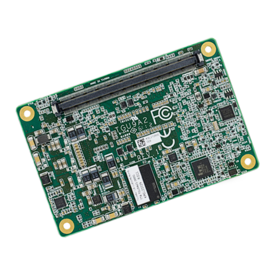
Chapter 3 - Hardware Installation Board Layout I225 LPDDR4X COM Express connector LPDDR4X BOTTOM www.dfi.com... -
Page 9: Block Diagram
PCIe_LANE 0~3 HSIO Lane 4-7 TCP2 NVMe SSD CPU_PCIE Gen4 Port 0-3 HSIO Lane 0-3 SPI BUS TPM 2.0 (Option) eSPI Serial Port 1/2 Embedded Controller Fan PWM/TACH_IN ITE8528 I2C BUS I2C BUS SMBUS SMBUS 8bit DIO GPIO 8bit www.dfi.com... -
Page 10: System Memory
ESD protection. COM Express connector System Memory The system board is equipped with 2 LPDDR4X memory chips onboard. LPDDR4X I225 Bottom View LPDDR4X Top View www.dfi.com... -
Page 11: Connectors
Connectors COM Express Connector The COM Express connector is used to interface the TGU9A2 COM Express board to a carrier board. Connect the COM Express connector (located on the solder side of the board) to the COM Express connector on the carrier board. - Page 12 AC/HDA_SDOUT / 3.3V Suspend I2C_CK / 3.3V Suspend AC/HDA_SDOUT / 3.3V Suspend I2C_CK / 3.3V Suspend PCIE_TX1+ PCIE_RX1+ BIOS_DIS0# I2C_DAT / 3.3V Suspend BIOS_DIS0# I2C_DAT / 3.3V Suspend PCIE_TX1- PCIE_RX1- THRMTRIP# / 3.3V Suspend THRM# THRMTRIP# / 3.3V Suspend THRM# www.dfi.com...
- Page 13 NC / USB_HOST_PRSNT 3.3V (option) USB6+ USB7+ USB6+ USB7+ TYPE10# / Pull down 47k ohm to GND SPI_CS# / 3.3V Suspend USB_6_7_OC# / 3.3V Suspend USB_4_5_OC# / 3.3V Suspend USB_6_7_OC# / 3.3V Suspend USB_4_5_OC# / 3.3V Suspend SER0_TX DDI0_CTRLCLK_AUX+ www.dfi.com...
-
Page 14: Com Express Connector Signal Description
AC coupled off Module PCI Express Differential Receive Pairs 1 Slot - Connect to PCIE Conn pin AC Coupling capacitor O PCIE AC coupled on Module Connect to PCIE device or slot PCI Express Differential Transmit Pairs 2 www.dfi.com AC Coupling capacitor... - Page 15 AC coupled off Module DDI 0 Pair 3 differential pairs/Serial Digital Video B clock output differential pair. DDI0_PAIR3-/DP0_LANE3- Connect AC Coupling Capacitors 0.1uF to Device NA for TGU9A2 NA for TGU9A2 NA for TGU9A2 PD 100K to GND I/O PCIE...
- Page 16 AC coupled on Module Additional transmit signal differential pairs for the SuperSpeed USB data path. AC Coupling capacitor and ESD suppressors to GND to USB connector www.dfi.com Connect 90Ω @100MHz Common Choke in series I PCIE AC coupled off Modul...
- Page 17 Additional receive signal differential pairs for the SuperSpeed USB data path. and ESD suppressors to GND to USB connector Module USB client may detect the presence of a USB host. A high value (NA for TGU9A2) indicates that a host is present. LVDS Signals Descriptions / l i...
- Page 18 Trusted Platform Module (TPM) Physical Presence pin. Active high. TPM chip has an internal pull down. This signal is used to indicate Physical Presence to the TPM. (NC for TGU9A2) Power and System Management Signals Descriptions / l i r e l...
- Page 19 Ground - DC power and signal and AC signal return path. A80, A90, A100, A110, B1, Power All available GND connector pins shall be used and tied to Carrier B11, B21 ,B31, B41, B51, Board GND plane. B60, B70, B80, B90, B100, B110 www.dfi.com...
-
Page 20: Cooling Option
TGU9A2 onto the carrier board of your choice. 1. Grasp TGU9A2 by its edges and position it on top of the carrier board with its COM Ex- press connector aligned with the COM Express connector on the carrier board. This will also help align the mountings holes of TGU9A2 with the standoffs on the carrier board. -
Page 21: Installing The Com Express Debug Card
The system board used in the following illustrations may not resemble the actual board. These illustrations are for reference only. 1. COMe-LINK2 is the COM Express debug platform installed into COM Express Mini modules for the application of debugging and displaying signals and codes. TGU9A2 Carrier board COM Express Connector 3. -
Page 22: Come-Debug
COM Express COM Express Type Display Signal Display COM Express Power/Reset/ Power Display Bolts Sleep/LID control 4. Use the provided bolts to fix the COMe-LINK2 debug card onto the carrier board. Cable COMe-DEBUG COMe-LINK2 Bolts COMe-LINK2 Carrier Board COMe-DEBUG www.dfi.com... - Page 23 6. Then, grasp the heat sink by its edges and position it down firmly on the top of the COM Express Mini module. Cable Carrier Board COM Express Mini Module COMe-LINK2 Side View of the Module, Debug Card and Carrier Board COMe-DEBUG www.dfi.com...
-
Page 24: Chapter 4 - Bios Setup
When “” appears on the left of a particular field, it indicates that a submenu which contains restart the system by pressing the <Ctrl> <Alt> and <Del> keys simultaneously. additional options are available for that field. To display the submenu, move the highlight to that field and press <Enter>. www.dfi.com... -
Page 25: Ami Bios Setup Utility
ME FW Version Select Item 15.0.10.1447 ↑↓: NVMe Configuration ME Firmware SKU Enter: Select Corporate SKU DFI EC HW Monitor +/ -: Change Opt. PMC FW Version 150.1.20.1028 DFI WDT Configuration F1: General Help F2: Previous Values Tls Auth Configuration ... -
Page 26: Cpu Configuration
GT Power Management Control options. Enable/ Disable the AVX 2/3 Instructions. AVX3 Enable/ Disable the AVX 3 Instructions. Active Processor Cores Choose how many cores of processor will be activated. Hyper-Threading Enable/ Disable the Intel HT technology. Enable/ Disable Advanced Encryption Standard. www.dfi.com... - Page 27 Power Limit 2 value in Milli Watts. BIOS will round to the nearest 1/8W when pro- gramming. 0 = no custom override. For 12.50W, enter 12500. Processor applies con- trol policies such that the package power does not exceed this limit. www.dfi.com...
- Page 28 Maximum GT frequency limited by the user. Choose between 100MHz (RPN) and 1350MHZ(RPO). Value beyond the range will be clipped to min/max supported by SKU Disable Turbo GT frequency Enabled: Disables Turbo GT frequency. Disabled: GT frequency is not limited www.dfi.com...
-
Page 29: Pcie Configuration
- PCIe RP Location for IMR: Select SA or PCH roor port associated with IMR When disabled, ME will not be unconfigured on RTC Clear. - RP index for IMR: Selects which root port will be associated with IMR ► Firmware Update Configuration Please refer to the following pages. www.dfi.com... -
Page 30: Trusted Computing
State of Security Device. This field is used to enable or disable the Me FW Image Re-Flash function. Platform Hierarchy Enable or Disable Platform Hierarchy. Storage Hierarchy Enable or Disable Storage Hierarchy Endorsement Hierarchy Enable or Disable Endorsement Hierarchy. www.dfi.com... -
Page 31: It8528 Super Io Configuration
Version 2.21.1278. Copyright (C) 2021 American Megatrends, Inc. Serial Port Configuration Console Redirection Set Parameters of Serial Ports. Console Redirection Enable or Disable. Console Redirection Settings See next page. Legacy Console Redirection Settings See following pages. Console Redirection EMS See following pages. www.dfi.com... - Page 32 Odd: parity bit is 0 if num of 1’s in the data bits is odd. Mark: parity bit is always 1. / Space: Parity bit is always 0. / Mark and Space Parity do not allow for error detection. www.dfi.com...
-
Page 33: Acpi Settings
When Boot loader is selected, then Legacy Console Redirection is disabled before booting to legacy OS. When Always Enable is selected, then Legacy Console Redirection is enabled for legacy OS. Default setting for this option is set to Always Enable. www.dfi.com... - Page 34 Device power-up delay [Auto] Select Screen →←: Select Item ↑↓: Enter: Select +/ -: Change Opt. F1: General Help F2: Previous Values F9: Optimized Defaults F10: Save & Exit ESC: Exit Version 2.21.1278. Copyright (C) 2021 American Megatrends, Inc. www.dfi.com...
-
Page 35: Network Stack Configuration
Enable/Disable IPv6 HTTP boot support. If disabled, IPv6 HTTP boot support will not be available. Media detect count Set the number of times the presence of media will be checked. Use either +/- or numeric keys to set the value. www.dfi.com... -
Page 36: Nvme Configuration
Namespace option will take lot longer to complete the test. Run Device Self Test Perform device self test for the corresponding Option and Act ion selected by user. Pressing ‘Esc’ key will abort the test. Result shown below is the recent result logged in the device. www.dfi.com... -
Page 37: Dfi Ec Hw Monitor
DFI EC HW Monitor Aptio Setup - AMI Smart Fan is a fan speed moderation strategy dependent on the current system Advanced temperature. When the system temperature goes higher than the Boundary setting, the fan speed will be turned up to the setting of the Fan Speed Count... -
Page 38: Dfi Wdt Configuration
DFI WDT Configuration Tls Auth Configuration Aptio Setup - AMI Aptio Setup - AMI Advanced Advanced DFI WDT Configuration Enable/Disable Watchdog Timer Server CA Configuration Press <Enter> to configure Server CA. Watchdog Timer [Enabled] Client Cert Configuration Output Options... -
Page 39: Ram Disk Configuration
Create a raw RAM Disk. See next page. Commit Changes and Exit Create from file Commit Changes and Exit Create a RAM disk from saved file. Discard Changes and Exit Remove selected RAM disk(s) Discard Changes and Exit Remove RAM disk from system. www.dfi.com... -
Page 40: System Agent (Sa) Configuration
Memory Configuration Parameter. Create & Exit Create the raw RAM Disk and exit. Graphics Configuration Settings about graphic. Discard & Exit Discard the change and exit. VMD setup menu VMD Configuration settings. PCI Express Configuration PCI Express Configuration settings www.dfi.com... -
Page 41: Memory Configuration
1: Makes all requests non protected and ignore range checks 2: Makes all requests protected and ignore range checks DVMT Total Gfx Mem Enable RH Prevention Select DVMT5.0 Total Graphic Memory size used by the Internal Graphics Device. Enable/Disable Memory Remap above 4GB. www.dfi.com... -
Page 42: Vmd Setup Menu
Intel Rapid Recovery Technology [Enabled] F1: General Help RRT volumes can span internal and [Enabled] F2: Previous Values eSATA drives F9: Optimized Defaults Intel(R) Optane(TM) Memory [Enabled] F10: Save & Exit ESC: Exit Version 2.21.1278. Copyright (C) 2021 American Megatrends, Inc. www.dfi.com... -
Page 43: Pci Express Configuration
Disable: Disable PCIe root port Select Screen →←: Select Item ↑↓: Enter: Select +/ -: Change Opt. F1: General Help F2: Previous Values F9: Optimized Defaults F10: Save & Exit ESC: Exit Version 2.18.1263. Copyright (C) 2018 American Megatrends, Inc. www.dfi.com... -
Page 44: Sata And Rst Configuration
AHCI feature is enabled on the OS. This option allows the Serial ATA controller(s) to use AHCI (Advanced Host Controller Interface). SATA Port 0 and 1/Hot Plug Enable or disable the Serial ATA port and its hot plug function. www.dfi.com... -
Page 45: Hd Audio Configuration
Version 2.21.1278. Copyright (C) 2021 American Megatrends, Inc. Audio Controller Hybrid Storage Detection and Configuration Mode Control the detection of the high-definition audio device. To enable or disable Hybrid Storage Detection and Configuration Mode. Disable HD Audio will be disabled. Enable HD Audio will be enabled. www.dfi.com... -
Page 46: Security
Set the supervisor password. Trusted Computing Pending operation This section configures settings relevant to Trusted Computing innovations. Schedule an operation for the security device. Note: Your computer will reboot during restarting in order to change the security device state. www.dfi.com... -
Page 47: Boot
Sets the driver boot order. This section is used to enable or disable UEFI network stack. When Network Stack is set to enabled, it will display Ipv4 PXE Support and Ipv6 PXE Support. Note: TGU9A2 only supports UEFI boot, no Legacy boot. www.dfi.com... -
Page 48: Save & Exit
Select Yes and then press <Enter> to exit the system setup and save your changes. Load Optimal Defaults Select Yes and then press <Enter> to load optimal defaults. Discard Changes Select Yes and then press <Enter> to exit the system setup without saving your changes. www.dfi.com... -
Page 49: Updating The Bios
For updating AMI BIOS in UEFI mode, Due to the safety concerns, the BIOS (SPI ROM) chip cannot be removed from this system you may refer to the how-to-video at https://www.dfi.com/Knowledge/Video/5 . board and used on another system board of the same model.
Need help?
Do you have a question about the TGU9A2 and is the answer not in the manual?
Questions and answers