
Related Manuals for DFI BW968


Summary of Contents for DFI BW968
- Page 1 BW968 COM Express Compact Module User’s Manual A38100644 Chapter 1 Introduction www.dfi.com...
-
Page 2: Copyright
Product names or trademarks appearing in this manual are for identification purpose only and 2. Shielded interface cables must be used in order to comply with the emission limits. are the properties of the respective owners. COM Express Specification Reference PICMG COM Express Module Base Specification. ® http://www.picmg.org/ Chapter 1 Introduction www.dfi.com... -
Page 3: Table Of Contents
Table of Contents Cooling Options �������������������������������������������������������������������������������������������������23 Installing BW968 onto a Carrier Board �������������������������������������������������������24 Installing the COM Express Debug Card �����������������������������������������������������26 Chapter 4 - BIOS Setup ��������������������������������������������������������28 Copyright ������������������������������������������������������������������������������������ 2 Overview �������������������������������������������������������������������������������������������������������������28 Trademarks ��������������������������������������������������������������������������������� 2 Insyde BIOS Setup Utility ���������������������������������������������������������������������������������29 Main ���������������������������������������������������������������������������������������������������������������������������������������������������� 29 COM Express Specification Reference ��������������������������������2... -
Page 4: About This Manual
To reduce the risk of electric shock: • Unplug the power cord before removing the system chassis cover for installation or servic- ing. After installation or servicing, cover the system chassis before plugging the power cord. Chapter 1 Introduction www.dfi.com... -
Page 5: About The Package
About the Package The package contains the following items. If any of these items are missing or damaged, please contact your dealer or sales representative for assistance. • One BW968 board • One DVD • One Heat sink (Height: TBD) Optional Items •... -
Page 6: Chapter 1 - Introduction
Audio Interface HD Audio Ethernet ® Controller 1 x Intel I211AT PCIe (10/100/1000Mbps) 4 x USB 3.0 8 x USB 2.0 SATA 2 x SATA 3.0 (up to 6Gb/s) 1 x 8-bit DIO Chapter 1 Introduction www.dfi.com... -
Page 7: Features
USB 1.1 (12Mb/s). USB 3.0 reduces the time required for data transmission, reduces power consumption, and is backward compatible with USB 2.0. It is a marked improvement in device transfer speeds between your computer and a wide range of simultaneously accessible external Plug and Play peripherals. Chapter 1 Introduction www.dfi.com... -
Page 8: Chapter 2 - Concept
Chapter 2 - Concept COM Express Module Standards The figure below shows the dimensions of the different types of COM Express modules. BW968 is a COM Express Compact module. The dimension is 95mm x 95mm. Common for all Form Factors Extended only... -
Page 9: Specification Comparison Table
0 / 2 1 / 1 Reset Functions 1 / 1 The table below shows the COM Express standard specifications and the corresponding specifications supported on the BW968 module. Watchdog Timer 0 / 1 Indicates 12V-tolerant features on former VCC_12V signals. -
Page 10: Chapter 3 - Hardware Installation
PCIe x1 Intel ® GLAN I211AT DDR3L_2 SODIMM USB 2.0 4x USB 2.0 4x USB 2.0 USB2517 SATA 3.0 2x SPI Bus Bottom View SPI Flash D110 COM Express connector C110 B110 COM Express connector A110 Chapter 3 Hardware Installation www.dfi.com... -
Page 11: Mechanical Diagram
Chapter 3 Mechanical Diagram BW968 Module BW968 Module with Heat Sink 101.00 94.00 83.00 7.00 16.00 49.91 0.30 Top View 12.50 78.75 87.25 88.50 Bottom View Side View of the Module with Heat Sink Chapter 3 Hardware Installation www.dfi.com... -
Page 12: System Memory
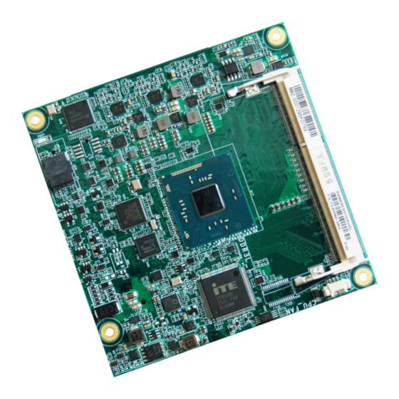
D110 COM Express connector C110 B110 DDR3L DDR3L_1 SODIMM COM Express connector A110 CPU Fan Bottom View Intel Pentium IT8528E Celeron Intel WGI211AT SMSC USB2517 Standby Power LED Flash BIOS Top View Chapter 3 Hardware Installation www.dfi.com... -
Page 13: Connectors
Chapter 3 Connectors COM Express Connectors The COM Express connectors are used to interface the BW968 COM Express board to a carrier CPU Fan Connector board. Connect the COM Express connectors (located on the solder side of the board) to the COM Express connectors on the carrier board. -
Page 14: Com Express Connectors
D109 VCC_12V GPI0 GPO1 A109 VCC_12V B109 VCC_12V C109 VCC_12V D109 VCC_12V A110 GND (FIXED) A110 GND (FIXED) B110 GND (FIXED) B110 GND (FIXED) C110 GND (FIXED) C110 GND (FIXED) D110 GND (FIXED) D110 GND (FIXED) Chapter 3 Hardware Installation www.dfi.com... -
Page 15: Com Express Connectors Signals And Descriptions
I/O Bi-directional input / output signal OD Open drain output AC97/HDA Signals and Descriptions Signal Pin# Module Pin Type Pwr Rail /Tolerance BW968 Carrier Board Description AC/HAD_RST# O CMOS 3.3V Suspend/3.3V Connect to CODEC pin 11 RESET# Reset output to CODEC, active low. - Page 16 PU 10K to 3.3V ATA (parallel and serial) or SAS activity indicator, active low. PCI Express Lanes Signals and Descriptions Signal Pin# Module Pin Type Pwr Rail /Tolerance BW968 Carrier Board Description PCIE_TX0+ AC Coupling capacitor O PCIE AC coupled on Module...
- Page 17 Connect to PCIE device, PCIe CLK Buffer or slot lanes. PEG Signals and Descriptions PCIE0_CK_REF- Signal Pin# Module Pin Type Pwr Rail /Tolerance BW968 Carrier Board Description PEG Signals and Descriptions PEG_TX0+ O PCIE AC coupled on Module PCI Express Graphics transmit differential pairs 0...
- Page 18 PU 10K to 3.3V board to reverse lane order. ExpressCard Signals and Descriptions Signal Pin# Module Pin Type Pwr Rail /Tolerance BW968 Carrier Board Description EXCD0_CPPE# PCI ExpressCard: PCI Express capable card request, active low, one per I CMOS 3.3V /3.3V...
- Page 19 Carrier DDI[n]_DDC_AUX_SEL should be connected to pin 13 of the DisplayPort USB Signals and Descriptions Signal Pin# Module Pin Type Pwr Rail /Tolerance BW968 Carrier Board Description USB0+ Connect 90Ω @100MHz Common Choke in series and ESD suppressors to GND to USB I/O USB 3.3V Suspend/3.3V...
- Page 20 Connect to DDC data of LVDS panel I2C data line for LVDS display use LPC Signals and Descriptions Signal Pin# Module Pin Type Pwr Rail /Tolerance BW968 Carrier Board Description LPC_AD0 LPC_AD1 I/O CMOS 3.3V / 3.3V LPC multiplexed address, command and data bus...
- Page 21 Serial Interface Signals and Descriptions Chapter 3 Signal Pin# Module Pin Type Pwr Rail /Tolerance BW968 Carrier Board Description General purpose serial port 0 transmitter SER0_TX O CMOS 3.3V/5V PD 4.7K to GND (Recommend add Protecting Logic Level Signals on Pins Reclaimed from VCC_12V)
- Page 22 GPIO Signals and Descriptions Chapter 3 Signal Pin# Module Pin Type Pwr Rail /Tolerance BW968 Carrier Board Description GPO0 GPO1 General purpose output pins. O CMOS 3.3V / 3.3V GPO2 Upon a hardware reset, these outputs should be low. GPO3 GPI0 PU 47K to 3.3V...
-
Page 23: Cooling Options
Bottom View of the Heat Sink • “1” denotes the location of the thermal pad/paste designed to contact the corre- sponding components that are on BW968. Important: Remove the plastic covering from the thermal pads prior to mounting the heat sink onto BW968. -
Page 24: Installing Bw968 Onto A Carrier Board
3. Press BW968 down firmly to seat it in the COM Express connectors of the carrier board. Pressing points 2. Grasp BW968 by its edges and position it on top of the carrier board with the mounting holes of BW968 aligning with the standoffs on the carrier board. This will also align the COM Express connectors of the two boards to each other. - Page 25 4. Verify that BW968 is firmly seated in the COM Express connectors of the carrier board. Carrier board BW968 5. Install a heat sink onto the BW968 with the carrier board. The photo below shows the heatsink installed on BW968. Chapter 3 Hardware Installation www.dfi.com...
-
Page 26: Installing The Com Express Debug Card
COM Express modules. COMe-LINK1 COMe-LINK1/2 Connector COMe-DEBUG Connector COM Express COM Express Type Display Signal Display COM Express Power/Reset/ Power Display Sleep/LID control COM Express Connectors Cable Top view COMe-DEBUG COMe-LINK1 COM Express Connectors Bottom view Chapter 3 Hardware Installation www.dfi.com... - Page 27 4. Use the provided screws to fix the COMe-LINK1 debug card onto the carrier board. Screws COMe-LINK1 Carrier Board COMe-DEBUG 5. Then use the instructions from the previous section to install BW968 and heatsink on the top of the COMe-LINK1 debug card. BW968 COMe-LINK1 Carrier Board...
-
Page 28: Chapter 4 - Bios Setup
“Press DEL to run setup” will appear on the screen. If the message disappears before you respond, restart the system or press the “Reset” button. You may also restart the system by pressing the <Ctrl> <Alt> and <Del> keys simultaneously. Chapter 4 BIOS Setup www.dfi.com... -
Page 29: Insyde Bios Setup Utility
The time format is <hour>, <minute>, <second>. The time is based on the 24-hour military-time clock. For example, 1 p.m. is 13:00:00. Hour displays hours from 00 to 23. Minute displays minutes from 00 to 59. Second displays seconds from 00 to 59. Chapter 4 BIOS Setup www.dfi.com... - Page 30 This field is to specify what state to go when power is re-applied after a power failure (G3 state). Always On Power on the system when power is re-applied after AC power loss. Always Off The system will be off when power is re-applied after AC power loss. Chapter 4 BIOS Setup www.dfi.com...
- Page 31 LCD Panel Color Depth Select the LCD panel color depth: 18 bit, 24 bit, 36 bit or 48 bit. Integrated Graphics Device Enable or disable Integrated Graphics Device when IGD is selected as the primary display. Chapter 4 BIOS Setup www.dfi.com...
- Page 32 Control the detection of the Azalia device. Disabled Serial ATA Port 0 and 1 Azalia will be unconditionally disabled. This field is used to enable or disable the serial ATA port. Enabled Azalia will be unconditionally enabled. Chapter 4 BIOS Setup www.dfi.com...
- Page 33 This field is used to enable or disable the PCI Express Root Port. Enable the USB XHCI PreBoot Support. Disabled Disable the USB XHCI PreBoot Support. PCIe Speed Select the speed of the PCI Express Root Port: Gen1 or Gen2. Chapter 4 BIOS Setup www.dfi.com...
- Page 34 COM Port 1 to COM Port 2 Configure the settings for each COM port. Disable Disable this COM port. Enable Enable this COM port. PC Health Status This field only displays the PC health information. Chapter 4 BIOS Setup www.dfi.com...
-
Page 35: Security
Windows 8 BitLocker Network Unlock, UEFI IPv4/IPv6 PXE and legacy PXE Set the supervisor’s password and the length of the password must be greater than one character. Option ROM. USB Boot Enable or disable the booting to USB boot devices. Chapter 4 BIOS Setup www.dfi.com... -
Page 36: Exit
Select this field and then press <Enter> to exit the system setup and save your changes. Load Optimal Defaults Select this field and then press <Enter> to load optimal defaults. Discard Changes Select this field and then press <Enter> to exit the system setup without saving your changes. Chapter 4 BIOS Setup www.dfi.com... -
Page 37: Updating The Bios
Insyde H20FFT (Flash Firmware Tool) Version (SEG) 100.00.08.10 Copyright(c) 2012 - 2016, Insyde Software Corp. All Rights Reserved. Initializing Current BIOS Model name: BW968 New BIOS Model name: BW968 Current BIOS version: 65.05A New BIOS version: 65.05A Updating Block at FFFFF000h... -
Page 38: Chapter 5 - Supported Software
If after inserting the DVD, “Autorun” did not automatically start (which is, the Mainboard Utility DVD screen did not appear), please go directly to the root directory of the DVD and double- click “Setup”. Auto Run Page (For Windows 10) Chapter 5 Supported Software www.dfi.com... - Page 39 Chapter 5 Auto Run Page (For Windows 7) Chapter 5 Supported Software www.dfi.com...
- Page 40 To install the utility, click “Intel Chipset Software Installation Utility” on the main menu. 1. Setup is now ready to install the utility. Click Next. 4. After completing installation, click Finish to exit setup. 2. Read the license agreement then click Yes. Chapter 5 Supported Software www.dfi.com...
- Page 41 We recommend that you skip this process by disabling this function then click “Next”. 2. Read the license agreement then click “Yes”. 5. Click “Yes, I want to restart this computer now” then click “Finish”. Restarting the system will allow the new software installation to take effect. Chapter 5 Supported Software www.dfi.com...
- Page 42 Finish. then click “Next”. Restarting the system will allow the new software installation to take effect. 3. Select the program featuers you want installed then click Next. Chapter 5 Supported Software www.dfi.com...
- Page 43 4. Click Install to begin the installation. To install the driver, click “Kernel Mode Driver Framework” on the main menu. 1. Click “Yes“ to install the update. 5. After completing installa- tion, click Finish. 2. The update is installed now. Chapter 5 Supported Software www.dfi.com...
- Page 44 To install the driver, click “Intel Trusted Execution Engine Driver” on the main menu. 1. Tick “I accept the terms in the License Agreement“ and then click “Next.” 2. The step shows the components which will be installed. Then, Click Next. Chapter 5 Supported Software www.dfi.com...
- Page 45 If you are using Windows 7 or later versions, you need to access the operat- ing system as an administrator to be able to install the utility. 1. Setup is ready to install the driver. 4. Click “Finish“ when the installation is complete. 2. Click “Next” to continue. Chapter 5 Supported Software www.dfi.com...
- Page 46 Note: The screenshot displayed above is for illustrative purpose only, and may not resemble the actual screen. The BW968 HW Utility features the following tabs: Information, HW Health, HW Healthset, Watchdog, DIO and Backlight. Click on the tabs to access information about the board.
- Page 47 1. Setup is ready to install the driver. Click Next. 4. Setup is currently installing the driver. After installation has com- pleted, click Next. 2. Read the license agreement then click Yes. 5. After completing installation, click Finish. Chapter 5 Supported Software www.dfi.com...
- Page 48 1. Setup is ready to install the driver. Click Next. 4. Setup is ready to install the driver. Click Next. 2. Read the license agreement care- fully. Click “I accept the terms in the cense Agreement” then click Next. Chapter 5 Supported Software www.dfi.com...
- Page 49 To install the reader, click “Adobe Acrobat Reader 9.3” on the main menu. 1. Click Next to install or click Change Destination Folder to select another folder. 6. Click Finish. 2. Click Install to begin installation. 3. Click Finish to exit installation. Chapter 5 Supported Software www.dfi.com...
-
Page 50: Appendix A - Troubleshooting
AC outlet. If necessary, try another outlet. 3. Check that the video input cable is properly attached to the monitor and the system’s display adapter. 4. Adjust the brightness of the display by turning the monitor’s brightness control knob Appendix A Troubleshooting www.dfi.com... - Page 51 Nothing happens when a key on the keyboard was pressed. 1. Make sure the keyboard is properly connected. 2. Make sure there are no objects resting on the keyboard and that no keys are pressed dur- ing the booting process. Appendix A Troubleshooting www.dfi.com...
-
Page 52: Appendix B - Insyde Bios Standard Status Post Code
Prepare to Boot to Legacy OS BDS_EXIT_BOOT_SERVICES Send END of POST Message to ME via HECI PostBDS Phase 8-Bit POST Code Values Functionality Name POST Code Value Description Appendix B Insyde BIOS Standard Status POST Code www.dfi.com POST_BDS_NO_BOOT_DEVICE No Boot Device...
Need help?
Do you have a question about the BW968 and is the answer not in the manual?
Questions and answers