
Related Manuals for DFI DV970


Summary of Contents for DFI DV970
- Page 1 DV970 COM Express Basic Module User’s Manual Preliminary Version A47900847 Chapter 1 Introduction www.dfi .com...
-
Page 2: Copyright
Copyright FCC and DOC Statement on Class B This publication contains information that is protected by copyright. No part of it may be re- This equipment has been tested and found to comply with the limits for a Class B digital produced in any form or by any means or used to make any transformation/adaptation without device, pursuant to Part 15 of the FCC rules. -
Page 3: Table Of Contents
................... 29 Cooling Option .................... 29 COM Express Specification Reference ........... 2 Heat Sink with Fan ..................29 Installing DV970 onto a Carrier Board ..........30 FCC and DOC Statement on Class B ............. 2 Warranty ......................4 Static Electricity Precautions .............. -
Page 4: Warranty
Warranty Static Electricity Precautions 1. Warranty does not cover damages or failures that arised from misuse of the product, in- It is quite easy to inadvertently damage your PC, system board, components or devices even ability to use the product, unauthorized replacement or alteration of components and prod- before installing them in your system unit. -
Page 5: About The Package
About the Package The package contains the following items. If any of these items are missing or damaged, please contact your dealer or sales representative for assistance. • One DV970 board • One Cooler (Height: TBD) Optional Items • COM333-I carrier board kit •... -
Page 6: Chapter 1 - Introduction
Chapter 1 Chapter 1 - Introduction Specifications SYSTEM Processor Intel Atom Processor C3000 Series, BGA1310 2 x USB 3.0 ® 4 x USB 2.0 Intel Atom C3958 Processor, 16 Cores, 16M Cache, 2.0GHz, 31W ® Intel Atom C3808 Processor, 12 Cores, 12M Cache, 2.0GHz, 25W SATA 2 x SATA 3.0 (up to 6Gb/s) ®... -
Page 7: Features
Chapter 1 Features • Watchdog Timer The Watchdog Timer function allows your application to regularly “clear” the system at the set time interval. If the system hangs or fails to function, it will reset at the set time interval so that your system will continue to operate. -
Page 8: Chapter 2 - Concept
Chapter 2 - Concept COM Express Module Standards The figure below shows the dimensions of the different types of COM Express modules. DV970 is a COM Express Basic module. Its dimension is 95mm x 125mm. Common for all Form Factors Extended only... -
Page 9: Specification Comparison Table
Specification Comparison Table The table below shows the COM Express standard specifications and the corresponding specifications supported on the DV970 module. Type 7 Based on Type 6. Modules trades all audio and video interfaces, 2 SATA ports and four USB 2.0 for... -
Page 10: Dv970 Pcie Lanes Routing Table
Chapter 2 DV970 PCIe Lanes Routing Table Chapter 2 Concept www.dfi .com... -
Page 11: Chapter 3 - Hardware Installation
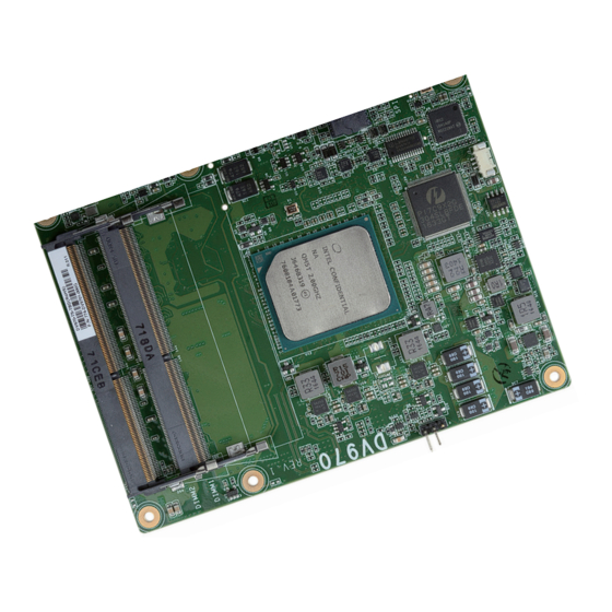
Chapter 3 Chapter 3 - Hardware Installation Board Layout Intel Atom C3000 Series P17C9X2G CPU fan 304SL Intel TPM (optional) I210AT or I210IT SPI Flash BIOS Standby Power LED Top View IT8528E D110 COM Express Connector C110 B110 COM Express Connector A110 A A A Bottom View... -
Page 12: System Memory
Chapter 3 Installing the DIMM Module Important: Electrostatic discharge (ESD) can damage your board, processor, disk drives, add-in boards, and other components. Perform installation procedures at an ESD workstation Note: only. If such a station is not available, you can provide some ESD protection by wear- The system board used in the following illustrations may not resemble the actual one. -
Page 13: Connectors
Chapter 3 5. Grasping the module by its edges, align the module into the socket at an approximately 30 Connectors degrees angle. Apply firm even pressure to each end of the module until it slips down into the socket. The contact fingers on the edge of the module will almost completely disappear CPU Fan Connector inside the socket. -
Page 14: Com Express Connectors
Chapter 3 COM Express Connectors The COM Express connectors are used to interface the DV970 COM Express board to a carrier board. Connect the COM Express connectors (located on the solder side of the board) to the COM Express connectors on the carrier board. - Page 15 VCC_12V B107 VCC_12V PCIE_TX5- PCIE_RX5- VCC_12V VCC_12V A108 B108 GPI0 GPO1 VCC_12V VCC_12V A109 B109 PCIE_TX4+ PCIE_RX4+ A110 GND (FIXED) B110 GND (FIXED) * : DV970 only supports LPC interface, no eSPI mode interface. Chapter 3 Hardware Installation www.dfi .com...
- Page 16 Chapter 3 Row C Row D Row C Row D PCIE_RX17- PCIE_TX17- GND (FIXED) GND (FIXED) N.C. TYPE2# USB_SSRX0- USB_SSTX0- PCIE_RX18+ PCIE_TX18+ USB_SSRX0+ USB_SSTX0+ PCIE_RX18- PCIE_TX18- GND (FIXED) GND (FIXED) USB_SSRX1- USB_SSTX1- PCIE_RX19+ PCIE_TX19+ USB_SSRX1+ USB_SSTX1+ PCIE_RX19- PCIE_TX19- RSVD RSVD N.C.
-
Page 17: Com Express Connectors Signal Discription
Gigabit Ethernet Signals Descriptions Signal Pin# Pin Type Pwr Rail /Tolerance COMe SPEC PU/PD DV970 PU/PD Module Base Specification R3.0 GBE0_MDI0+ I/O Analog 3.3V max Suspend Gigabit Ethernet Controller 0: Media Dependent Interface Differential Pairs GBE0_MDI0- I/O Analog 3.3V max Suspend 0,1,2,3. - Page 18 10Gb Ethernet Signals Descriptions Signal Pin# Pin Type Pwr Rail /Tolerance COMe SPEC PU/PD DV970 PU/PD Module Base Specification R3.0 10GBASE-KR ports, transmit output differential pairs. 10G_KR_TX0+ O KR AC coupled at receiver See section ‘AC Coupling of 10G_KR_TX Signals‘ below for details on AC coupling 10GBASE-KR ports, transmit output differential pairs.
- Page 19 SATA Signals Descriptions Signal Pin# Pin Type Pwr Rail /Tolerance COMe SPEC PU/PD DV970 PU/PD Module Base Specification R3.0 SATA0_TX+ O SATA AC coupled on Module AC Coupling capacitor Serial ATA Channel 0 transmit differential pair.
- Page 20 3.3V General Purpose PCI Express Lanes Signals Descriptions Signal Pin# Pin Type Pwr Rail /Tolerance COMe SPEC PU/PD DV970 PU/PD Module Base Specification R3.0 PCIE_TX0+ AC Coupling capacitor O PCIE AC coupled on Module PCI Express Differential Transmit Pairs 0...
- Page 21 Chapter 3 PCIE_TX11+ N.C. PCI Express Differential Transmit Pairs 11 O PCIE AC coupled on Module Different connector layout for Type 7 PCIE_TX11- N.C. PCIE_RX11+ N.C. PCI Express Differential Receive Pairs 11 I PCIE AC coupled off Module PCIE_RX11- N.C. Different connector layout for Type 7 PCIE_TX12+ AC Coupling capacitor...
- Page 22 USB Signals Descriptions Signal Pin# Pin Type Pwr Rail /Tolerance COMe SPEC PU/PD DV970 PU/PD Module Base Specification R3.0 USB differential pairs, channels 0. For type 7 only, USB0 may be configured as a USB0+ I/O USB 3.3V Suspend/3.3V USB client or as a host, or both at the Module designer's discretion. All other USB USB0- ports, if implemented, shall be host ports.
- Page 23 LPC and eSPI Signals Descriptions Signal Pin# Pin Type Pwr Rail /Tolerance COMe SPEC PU/PD DV970 PU/PD (LPC mode) Module Base Specification R3.0 LPC_AD0 / ESPI_IO_0 LPC Mode: LPC multiplexed address, command and data bus. LPC_AD1 / ESPI_IO_1 3.3V / 3.3V I/O CMOS...
- Page 24 Signal Pin# Pin Type Pwr Rail /Tolerance COMe SPEC PU/PD DV970 (SPI_3VDU) PU/PD Module Base Specification R3.0 3.3V Suspend / 3.3V SPI_CS# O CMOS Chip select for Carrier Board SPI - may be sourced from chipset SPI0 or SPI1 1.8V Suspend / 3.3V 3.3V Suspend / 3.3V...
- Page 25 Miscellaneous Signal Descriptions Signal Pin# Pin Type Pwr Rail /Tolerance COMe SPEC PU/PD DV970 PU/PD Module Base Specification R3.0 Output for audio enunciator - the "speaker" in PC-AT systems. This port provides SPKR O CMOS 3.3V / 3.3V the PC beep signal and is mostly intended for debugging purposes.
- Page 26 Chapter 3 Thermal Protection Signals Descriptions Signal Pin# Pin Type Pwr Rail /Tolerance COMe SPEC PU/PD DV970 PU/PD Module Base Specification R3.0 THRM# I CMOS 3.3V / 3.3V IPU 10K to 3.3V Input from off-Module temp sensor indicating an over-temp situation.
- Page 27 Pin Type Pwr Rail /Tolerance COMe SPEC PU/PD DV970 PU/PD (T7) Module Base Specification R3.0 The TYPE pins indicate to the Carrier Board the Pin-out Type that is implemented on the Module. The pins are tied on the Module to either ground (GND) or are no-connects (NC).
- Page 28 Chapter 3 Dual use pin. Indicates to the Carrier Board that a Type 10 Module is installed. Indicates to the Carrier that a Rev 1.0 or a Rev 2.0/3.0 Module is installed. TYPE10# NC Pin-out R2.0 PD Pin-out Type 10 pull down to ground with 47K resistor 12V Pin-out R1.0 TYPE10# N.C.
-
Page 29: Standby Power Led
Bottom View of the Heat Sink • “1” denotes the location of the thermal pad designed to contact the cor- responding components on DV970. Important: Remove the plastic covering from the thermal pads prior to mounting the heat sink onto DV970. -
Page 30: Installing Dv970 Onto A Carrier Board
Pressing points 1. Grasp DV970 by its edges and position it on top of the carrier board with its mounting holes aligned with the standoffs on the carrier board. This helps align the COM Express connectors of the two boards to each other. - Page 31 Chapter 3 3. Install a heat sink onto the DV970 with the carrier board. First align the mounting holes of the heat sink with the mounting holes of the module. Heat sink DV970 Carrier board Side View of the Heat sink, Module, and Carrier Board...
Need help?
Do you have a question about the DV970 and is the answer not in the manual?
Questions and answers