Table of Contents
Advertisement
Quick Links
Advertisement
Table of Contents

Related Manuals for DFI AL9A8


Summary of Contents for DFI AL9A8
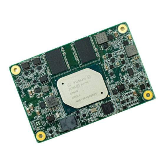
- Page 1 AL9A8 COM Express Mini Module User’s Manual A46200902 www.dfi.com...
-
Page 2: Copyright
2. Shielded interface cables must be used in order to comply with the emission limits. COM Express Specification Reference PICMG ® COM Express ® Module Base Specification. http://www.picmg.org/ www.dfi.com... -
Page 3: Table Of Contents
Connectors ��������������������������������������������������������������������������������������������������� 12 COM Express Connector ������������������������������������������������������������������������������ 12 COM Express Connector Signal Discription ��������������������������������������������������� 15 Cooling Option �������������������������������������������������������������������������������������������� 21 Heat Sink ��������������������������������������������������������������������������������������������������� 21 Installing AL9A8 onto a Carrier Board ������������������������������������������������� 21 Installing the COM Express Debug Card ��������������������������������������������� 22 www.dfi.com... -
Page 4: Warranty
Use the correct AC input voltage range. To reduce the risk of electric shock: • Unplug the power cord before removing the system chassis cover for installation or servic- ing. After installation or servicing, cover the system chassis before plugging the power cord. www.dfi.com... -
Page 5: About The Package
The package contains the following items. If any of these items are missing or damaged, please contact your dealer or sales representative for assistance. • 1 AL9A8 board Optional Items The board and accessories in the package may not come similar to the information listed above. -
Page 6: Chapter 1 - Introduction
-40 to 85°C Humidity Operating: 5 to 90% RH Storage: 5 to 90% RH MTBF MECHANICAL Dimensions COM Express Mini 84mm (3.30") x 55mm (2.16") ® Compliance PICMG COM Express R2.1, Type 10 ® CERTIFICATIONS Certifications CE, FCC, RoHS, UKCA www.dfi.com... -
Page 7: Chapter 2 - Concept
Chapter 2 - Concept COM Express Module Standards The figure below shows the dimensions of the different types of COM Express modules. AL9A8 is a COM Express Mini. The dimension is 84mm x 55mm. Common for all Form Factors Extended only... -
Page 8: Specification Comparison Table
1(option) Reset Functions 1 / 1 The table below shows the COM Express standard specifications and the corresponding specifications supported on the AL9A8 module. General Purpose I/O 8 / 8 Table 3.2: Module Pin-out - Required and Optional Features A-B Connector Indicates 12V-tolerant features on former VCC_12V signals. -
Page 9: Chapter 3 - Hardware Installation
Chapter 3 - Hardware Installation Block Diagram Board Layout Intel Atom PTN3460 SPI Flash BIOS eMMC (optional) Intel I210AT or I210IT B110 COM Express Connector A110 BOTTOM www.dfi.com... -
Page 10: Connectors
Connectors COM Express Connector The COM Express connector is used to interface the AL9A8 COM Express board to a carrier board. Connect the COM Express connector (located on the solder side of the board) to the COM Express connector on the carrier board. - Page 11 AC/HDA_SDOUT / 3.3V Suspend I2C_CK / 3.3V Suspend AC/HDA_SDOUT / 3.3V Suspend I2C_CK / 3.3V Suspend PCIE_TX1+ PCIE_RX1+ BIOS_DIS0# I2C_DAT / 3.3V Suspend BIOS_DIS0# I2C_DAT / 3.3V Suspend PCIE_TX1- PCIE_RX1- THRMTRIP# / 3.3V Suspend THRM# THRMTRIP# / 3.3V Suspend THRM# www.dfi.com...
- Page 12 NC / USB_HOST_PRSNT 3.3V (option) USB6+ USB7+ USB6+ USB7+ TYPE10# / Pull down 47k ohm to GND SPI_CS# / 3.3V Suspend USB_6_7_OC# / 3.3V Suspend USB_4_5_OC# / 3.3V Suspend USB_6_7_OC# / 3.3V Suspend USB_4_5_OC# / 3.3V Suspend SER0_TX DDI0_CTRLCLK_AUX+ www.dfi.com...
-
Page 13: Com Express Connector Signal Discription
AC coupled off Module PCI Express Differential Receive Pairs 1 Slot - Connect to PCIE Conn pin AC Coupling capacitor O PCIE AC coupled on Module Connect to PCIE device or slot PCI Express Differential Transmit Pairs 2 www.dfi.com AC Coupling capacitor... - Page 14 DDI[n]_DDC_AUX_SEL shall be pulled to 3.3V on the Carrier with a 100K Ohm resistor to configure the DDI[n]_AUX pair as the DDC channel. Carrier DDI[n]_DDC_AUX_SEL should be connected to pin 13 of the DisplayPort USB Signals Descriptions www.dfi.com / l i r e l r e i...
- Page 15 AC coupled on Module Additional transmit signal differential pairs for the SuperSpeed USB data path. AC Coupling capacitor and ESD suppressors to GND to USB connector www.dfi.com Connect 90 @100MHz Common Choke in series I PCIE AC coupled off Modul...
- Page 16 The Carrier should only float these or pull them low, please refer to COM Express Module Base Specification Revision 2.1 for strapping options of BIOS disable signals. Serial Interface Signals Descriptions www.dfi.com / l i r e l r e i...
- Page 17 l...
- Page 18 Ground - DC power and signal and AC signal return path. A80, A90, A100, A110, B1, Power All available GND connector pins shall be used and tied to Carrier B11, B21 ,B31, B41, B51, Board GND plane. B60, B70, B80, B90, B100, B110 www.dfi.com...
-
Page 19: Cooling Option
AL9A8 onto the carrier board of your choice. 1. Grasp AL9A8 by its edges and position it on top of the carrier board with its COM Express connector aligned with the COM Express connector on the carrier board. This will also help align the mountings holes of AL9A8 with the standoffs on the carrier board. -
Page 20: Installing The Com Express Debug Card
The system board used in the following illustrations may not resemble the actual board. These illustrations are for reference only. 1. COMe-LINK2 is the COM Express debug platform installed into COM Express Mini modules for the application of debugging and displaying signals and codes. AL9A8 Carrier board COM Express Connector 3. - Page 21 COM Express COM Express Type Display Signal Display COM Express Power/Reset/ Power Display Bolts Sleep/LID control 4. Use the provided bolts to fix the COMe-LINK2 debug card onto the carrier board. Cable COMe-DEBUG COMe-LINK2 Bolts COMe-LINK2 Carrier Board COMe-DEBUG www.dfi.com...
- Page 22 6. Then, grasp the heat sink by its edges and position it down firmly on the top of the COM Express Mini module. Cable Carrier Board COM Express Mini Module COMe-LINK2 Side View of the Module, Debug Card and Carrier Board COMe-DEBUG www.dfi.com...
-
Page 23: Chapter 4 - Bios Setup
When “” appears on the left of a particular field, it indicates that a submenu which contains restart the system by pressing the <Ctrl> <Alt> and <Del> keys simultaneously. additional options are available for that field. To display the submenu, move the highlight to that field and press <Enter>. www.dfi.com... -
Page 24: Ami Bios Setup Utility
Aptio Setup Utility - Copyright (C) 2018 American Megatrends, Inc. Setting incorrect field values may cause the system to malfunction. Main Advanced Security Boot Save & Exit Project Name AL9A8 Set the Time. Use Tab BIOS Version 214.29B to switch between Time EC Version 2021.03.30 v0.2 elements. - Page 25 This field is to specify what state the system should be in when power is re-applied after a power failure (G3, the mechanical-off, state). Always On The system is in working state. Always Off The system is in soft-off state, except for trickle current to devices such as the power button. www.dfi.com...
- Page 26 1280X1024 or 1920X1080. Enable or disable CPU Power Management. It allows CPU to go to C States when it’s LCD Panel Color Depth not 100% utilized. Select the LCD panel color depth: 18 Bit, 24 Bit, 36 Bit or 48 Bit. www.dfi.com...
- Page 27 Interface). SATA Interface Speed Select Serial ATA controller(s) speed from Gen1 (1.5 Gbit/s), Gen2 (3 Gbit/s) or Gen 3 (6 Gbit/s). SATA Port 0 and 1/Hot Plug Enable or disable the Serial ATA port and its hot plug function. www.dfi.com...
- Page 28 Select the speed of the PCI Express root port: Auto, Gen1 or Gen2. root port Select Screen →←: Select Item ↑↓: Enter: Select +/ -: Change Opt. F1: General Help F2: Previous Values F9: Optimized Defaults F10: Save & Exit ESC: Exit Version 2.18.1263. Copyright (C) 2018 American Megatrends, Inc. www.dfi.com...
- Page 29 Select stop bits: 1 bit or 2 bits. Select Screen →←: Select Item ↑↓: Enter: Select +/ -: Change Opt. F1: General Help F2: Previous Values F9: Optimized Defaults F10: Save & Exit ESC: Exit Version 2.18.1263. Copyright (C) 2018 American Megatrends, Inc. www.dfi.com...
- Page 30 F9: Optimized Defaults F9: Optimized Defaults F10: Save & Exit F10: Save & Exit ESC: Exit ESC: Exit Version 2.18.1263. Copyright (C) 2018 American Megatrends, Inc. Version 2.18.1263. Copyright (C) 2018 American Megatrends, Inc. Watchdog Timer Enable or disable watchdog timer. www.dfi.com...
- Page 31 The enable delay allows time for the OS to boot and the application to load and initial- ize. The unit is 1 sec. Timeout Delay The timeout delay allows time for period of the watchdog timer. The unit is 0.1 sec. www.dfi.com...
- Page 32 Select Item ↑↓: Enter: Select +/ -: Change Opt. F1: General Help F2: Previous Values F9: Optimized Defaults F10: Save & Exit ESC: Exit Version 2.18.1263. Copyright (C) 2018 American Megatrends, Inc. DPIO/GPIO Select Select DIO or GPIO funtion. www.dfi.com...
-
Page 33: Security
F1: General Help F2: Previous Values F9: Optimized Defaults F10: Save & Exit ESC: Exit Version 2.18.1263. Copyright (C) 2018 American Megatrends, Inc. Serial Port 1 and 2 This field is used to enable or disable the serial port (COM). www.dfi.com... -
Page 34: Boot
This section is used to enable or disable quiet boot option. Network Stack This section is used to enable or disable UEFI network stack. When Network Stack is set to enabled, it will display Ipv4 PXE Support and Ipv6 PXE Support. www.dfi.com... -
Page 35: Save & Exit
Boot Option Priorities Select Yes and then press <Enter> to exit the system setup without saving your changes. Sets the system boot order. Driver Option Priorities Sets the driver boot order. Note: AL9A8 only supports UEFI boot, no Legacy boot� www.dfi.com... -
Page 36: Updating The Bios
For updating AMI BIOS in UEFI mode, Due to the safety concerns, the BIOS (SPI ROM) chip cannot be removed from this system you may refer to the how-to-video at https://www.dfi.com/Knowledge/Video/5 . board and used on another system board of the same model. -
Page 37: Chapter 5 - Supported Software
INF files so that ® the Intel chipset can be recognized and configured properly in the system. To install the utility, download “AL9A8 Chipset Driver” zip file at our website. 1. Setup is ready to install the utility. Click “Next”. - Page 38 Intel Graphics Driver 3. Go through the readme document for system re- To install the driver, download “AL9A8 Graphics Driver” zip file at our website. quirements and installation tips then click “Next”. 1. Setup is now ready to install the graphics driver.
- Page 39 Audio Drivers Intel LAN Driver To install the driver, download “AL9A8 Audio Driver” zip file at our website. To install the driver, download “AL9A8 LAN Driver” zip file at our website. 1. Setup is ready to install the 1. Setup is ready to install the driver.
- Page 40 4. Click “Install” to begin the 6. After completing installa- installation. tion, click “Finish”. 5. The step displays the installing status in the prog- ress. www.dfi.com...
- Page 41 Intel Trusted Execution Engine Driver 3. The step displays the installing status in the progress. To install the driver, download “AL9A8 TXE Driver” zip file at our website. 1. Tick “I accept the terms in the License Agreement” and then click “Next”.
- Page 42 SIO Driver 3� Read the file information then click “Next”� To install the driver, download “AL9A8 SIO Driver” zip file at our website. 1. Setup is ready to install the driver. Click “Next”. 4. Setup is ready to install the driver.
- Page 43 5. Setup is now installing the driver. 6. Click “Finish”. www.dfi.com...
-
Page 44: Chapter 6 - Gpio Programming Code
Return Data ; GPIO Output Process EC_DIO_Write_Output(unsigned char udata) //Pin4-7 Output Mode udata <<= 4; udata |= 0x01; Write_EC_Data(0xBB, udata); return 0; EC_DIO_Read_Output() BYTE Data; //Pin4-7 Output Mode Write_EC_Data(0xBB, 0x02); Delay; Data = Get_EC_Data(0xBB); Data >>= 4; Return Data ; www.dfi.com... -
Page 45: Appendix A - Watchdog Sample Code
Remaining: %d ",countdown); //-------------------------------------------------------------- void WriteEC(char EC_Addr, int data) //-------------------------------------------------------------- //Select EC Write Type void SetWDTime(int count_H,int count_L) outportb(EC_EnablePort,0x81); delay(5); //Set Count outportb(EC_DataPort,EC_Addr); WriteEC(0xB5,count_H); //High Byte delay(5); WriteEC(0xB6,count_L); //Low Byte outportb(EC_DataPort,data); //Enable Watch Dog Timer delay(5); WriteEC(0xB4,0x01); //-------------------------------------------------------------- //-------------------------------------------------------------- www.dfi.com... -
Page 46: Appendix B - System Error Message
0xA3 IDE Enable 0xA1 IDE Reset 0xAE Legacy Boot event 0xA2 IDE Detect 0xB4 USB hot plug 0xA3 IDE Enable 0xB6 Clean-up of NVRAM 0xAE Legacy Boot event 0xB7 Configuration Reset (reset of NVRAM settings) www.dfi.com 0xB4 USB hot plug... - Page 47 System has transitioned into ACPI mode. Interrupt controller is in PIC mode. Beep Code 0xAA System has transitioned into ACPI mode. Interrupt controller is in APIC mode. Beep Code beeps Flash update is failed Beep Code beeps Flash update is failed www.dfi.com...
-
Page 48: Appendix C - Troubleshooting
AC outlet. If necessary, try another outlet. 3. Check that the video input cable is properly attached to the monitor and the system’s display adapter. 4. Adjust the brightness of the display by turning the monitor’s brightness control knob � www.dfi.com... - Page 49 Nothing happens when a key on the keyboard was pressed. 1. Make sure the keyboard is properly connected. 2. Make sure there are no objects resting on the keyboard and that no keys are pressed dur- ing the booting process. www.dfi.com...
Need help?
Do you have a question about the AL9A8 and is the answer not in the manual?
Questions and answers