
Related Manuals for DFI WL968


Summary of Contents for DFI WL968
- Page 1 WL968 COM Express Compact Module User’s Manual A-617-M-2046 Chapter 1 Introduction www.dfi.com ver.a_MP_12-1420_13-37...
- Page 2 Product names or trademarks appearing in this manual are for identification purpose only and 2. Shielded interface cables must be used in order to comply with the emission limits. are the properties of the respective owners. COM Express Specification Reference PICMG COM Express Module Base Specification. ® http://www.picmg.org/ Chapter 1 Introduction www.dfi.com...
-
Page 3: Table Of Contents
COM Express Connectors Signals and Descriptions ....... 14 Standby Power LED ............... 21 Cooling Option ............... 21 Installing WL968 onto a Carrier Board ........22 Installing the COM Express Debug Card (Optional) ....24 Chapter 4 - BIOS Setup ........26 Overview ................ - Page 4 To reduce the risk of electric shock: • Unplug the power cord before removing the system chassis cover for installation or servic- ing. After installation or servicing, cover the system chassis before plugging the power cord. Chapter 1 Introduction www.dfi.com...
- Page 5 About the Package The package contains the following items. If any of these items are missing or damaged, please contact your dealer or sales representative for assistance. • 1 WL968 board • 1 CPU Cooler (for -40 to 85°C, H=35.2mm): A71-108124-000G •...
-
Page 6: Chapter 1 - Introduction
I219LM with iAMT12.x PCIe (10/100/1000Mbps) 4 x USB 3.0 8 x USB 2.0 SATA Default 2 x SATA , 3 x SATA by BOM request, SATA 3.0 (up to 6Gb/s) RAID 0/1/5 1 x 8-bit DIO Chapter 1 Introduction www.dfi.com... - Page 7 USB 1.1 (12Mb/s). USB 3.0 reduces the time required for data transmission, reduces power consumption, and is backward compatible with USB 2.0. It is a marked improvement in device transfer speeds between your computer and a wide range of simultaneously accessible external Plug and Play peripherals. Chapter 1 Introduction www.dfi.com...
-
Page 8: Chapter 2 - Concept
The dimension of COM Express Compact module is 95mm x 95mm. Common for all Form Factors Extended only Basic only Compact only Compact and Basic only Mini only 106.00 Extended 91.00 Compact Basic 70.00 51.00 Mini 18.00 6.00 4.00 0.00 Chapter 1 Introduction www.dfi.com... -
Page 9: Specification Comparison Table
Specification Comparison Table The table below shows the COM Express standard specifications and the corresponding specifications supported on the WL968 module. Module Pin-out - Required and Optional Features A-B Connector. PICMG COM.0 Revision 2.1 Module Pin-out - Required and Optional Features C-D Connector. PICMG COM.0 Revision 2.1... -
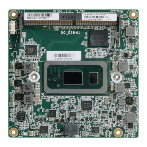
Page 10: Chapter 3 - Hardware Installation
Board Layout SO_DIMM1 CPU Fan IT8528VG Intel Top View BGA 1528 TPM (optional) PTN3460 Chrontel Intel SPI Flash BIOS I219LM CH7517 Standby Power LED SO_DIMM1 Bottom View D110 COM Express Connector C110 B110 COM Express Connector A110 Chapter 1 Introduction www.dfi.com... -
Page 11: System Memory
COM Express Connector C110 B110 DDR4 COM Express Connector A110 SO_DIMM1 Bottom View CPU Fan IT8528VG Intel BGA 1528 TPM (optional) PTN3460 Chrontel Intel SPI Flash BIOS I219LM CH7517 Standby Power LED Standby Power LED Top View Chapter 1 Introduction www.dfi.com... -
Page 12: Connectors
Connectors COM Express Connectors The COM Express connectors are used to interface the WL968 COM Express board to a carrier CPU Fan Connector board. Connect the COM Express connectors (located on the solder side of the board) to the COM Express connectors on the carrier board. -
Page 13: Com Express Connectors
PCIE_TX5- PCIE_RX5- A108 VCC_12V B108 VCC_12V C108 VCC_12V D108 VCC_12V GPI0 GPO1 A109 VCC_12V B109 VCC_12V TYPE0# PEG_LANE_RV# C109 VCC_12V D109 VCC_12V PCIE_TX4+ PCIE_RX4+ A110 GND (FIXED) B110 GND (FIXED) C110 GND (FIXED) D110 GND (FIXED) Chapter 1 Introduction www.dfi.com... -
Page 14: Com Express Connectors Signals And Descriptions
I/O Bi-directional input / output signal OD Open drain output AC97/HDA Signals Descriptions Signal Pin# Module Pin Type Pwr Rail / Tolerance WL968 Carrier Board Description AC/HDA_RST# O CMOS 3.3V Suspend/3.3V Connect to CODEC pin 11 RESET# Reset output to CODEC, active low. - Page 15 Serial ATA or SAS Channel 2 receive differential pair. SATA2_RX- I SATA AC coupled on Module Signal Pin# Module Pin Type Pwr Rail / Tolerance WL968 Carrier Board Description SATA3_TX+ O SATA AC coupled on Module PCIE_TX0+ AC Coupling capacitor Serial ATA or SAS Channel 3 transmit differential pair.
- Page 16 I PCIE AC coupled off Module PCI Express Graphics receive differential pairs 11 Signal PEG_RX11- Pin# Module Pin Type Pwr Rail / Tolerance WL968 Carrier Board Description PEG_TX0+ PEG_TX12+ O PCIE O PCIE AC coupled on Module AC coupled on Module...
- Page 17 Carrier DDI[n]_DDC_AUX_SEL should be connected to pin 13 of the DisplayPort USB Signals Descriptions Signal Pin# Module Pin Type Pwr Rail / Tolerance WL968 Carrier Board Description USB0+ Connect 90 @100MHz Common Choke in series and ESD suppressors to GND to USB I/O USB 3.3V Suspend/3.3V...
- Page 18 Additional receive signal differential pairs for the SuperSpeed USB data path. USB_SSRX3- connector LVDS Signals Descriptions Signal Pin# Module Pin Type Pwr Rail / Tolerance WL968 Carrier Board Description Connect to LVDS connector LVDS Channel A differential pairs LVDS_A0+ O LVDS LVDS Ther LVDS flat panel differential pairs (LVDS_A[0:3]+/-, LVDS_B[0:3]+/-.
- Page 19 VGA Signals Descriptions Signal Pin# Module Pin Type Pwr Rail / Tolerance Carrier Board Description WL968 VGA_RED O Analog Analog PD 150 to GND PD 150R,connect to VGA connector with EMI filter & ESD protect component. Red for monitor. Analog output...
- Page 20 (Recommend add Protecting Logic Level Signals on Pins Reclaimed from VCC_12V) Signal Pin# Module Pin Type Pwr Rail / Tolerance WL968 Carrier Board Description A falling edge creates a power button event. Power button events can Sleep button. Low active signal used by the ACPI operating system to bring the...
-
Page 21: Standby Power Led
Bottom View of the Heat Sink • “1” denotes the location of the thermal pad designed to contact the corresponding components that are on the WL968. Important: Remove the plastic covering from the thermal pads prior to mounting the heat sink onto the WL968. -
Page 22: Installing Wl968 Onto A Carrier Board
WL968 1. Grasp WL968 by its edges and position it on top of the carrier board with the mounting holes of WL968 aligning with the standoffs on the carrier board. This will also align the COM Express connectors of the two boards to each other. - Page 23 3. Use the provided mounting screws to secure WL968 with heat sink to the carrie board. The photo below shows the locations of the long mounting screws. Long screws Chapter 1 Introduction www.dfi.com...
-
Page 24: Installing The Com Express Debug Card (Optional)
COM Express modules. COMe-LINK1 COMe-LINK1/2 Connector COMe-DEBUG Connector COM Express COM Express Type Display Signal Display COM Express Power/Reset/ Power Display Sleep/LID control COM Express Connectors Cable Top view COMe-DEBUG COMe-LINK1 COM Express Connectors Bottom view Chapter 1 Introduction www.dfi.com... - Page 25 Carrier Board COMe-DEBUG 4. Then use the instructions from the previous section to install SU968 and heat sink on the top of the COMe-LINK1 debug card. WL968 COMe-LINK1 Carrier Board Side View of the Module, Debug Card and Carrier Board Chapter 1 Introduction www.dfi.com...
-
Page 26: Chapter 4 - Bios Setup
“Press DEL to run setup” will appear on the screen. If the message disappears before you respond, restart the system or press the “Reset” button. You may also restart the system by pressing the <Ctrl> <Alt> and <Del> keys simultaneously. Chapter 1 Introduction www.dfi.com... -
Page 27: Insyde Bios Setup Utility
Aptio Setup Utility - Copyright (C) 2019 American Megatrends, Inc. Main Advanced Chipset Security Boot Save & Exit Project Name WL968 Set the Date. Use Tab to BIOS Version B209.26C switch between Date ele- EC Version E204.28A. v0.3 ments. Default Ranges: Aptio Setup Utility - Copyright (C) 2019 American Megatrends, Inc. -
Page 28: Acpi Configuration
The system returns to the last state right before power failure. Wake up time When Wake On RTC is set to enabled, specify the wake up time of the day: <hour> (00~23), <minute> (00~59), <second> (00~59). Chapter 1 Introduction www.dfi.com... -
Page 29: Cpu Configuration
Enable or disable CPU Power Management. It allows CPU to enter “C states” when it’s idle and nothing is executing. Note: Some of the fields may not be available when the features are not supported by the equipped CPU. Chapter 1 Introduction www.dfi.com... -
Page 30: Pch-Fw Configuration
When disabled, AMT BIOS features are no longer supported and user is no longer able to ac- cess MEBx Setup. This option does not disable manageability features in FW. ME Unconfig on RTC Clear When disabled, ME will not be unconfigured on RTC Clear. Note: The sub-menus are detailed in following sections. Chapter 1 Introduction www.dfi.com... - Page 31 Enable or disable to hide unconfigure ME confirmation prompt when attempting ME unconfiguration. Force Secure Erase Unconfigure ME Enable or disable Force Secure Erase on next boot. Enable or disable to unconfigure ME with resetting MEBx password to default. Chapter 1 Introduction www.dfi.com...
-
Page 32: Trusted Computing
ME firmware. 2.0 to achieve hardware-level security via cryptographic keys. Pending operation To clear the existing TPM encryption, select “TPM Clear” and restart the system. This field is not available when “Security Device Support” is disabled. Chapter 1 Introduction www.dfi.com... -
Page 33: Ptn3460 Configuration
Select the resolution of the LCD Panel — 800X480, 800X600, 1024X768, 1366X768, 1280X1024, 1280X768, 1920X1080, or 1600X900. LCD Panel Color Depth Select the color depth of the LCD Panel — 18 Bit, 24 Bit, 36 Bit, 48 Bit Chapter 1 Introduction www.dfi.com... -
Page 34: It8528 Super Io Configuration
The sub-menus are detailed in following sections. Serial Port Enable or disable the current serial COM port. Change Settings Select an I/O Address and IRQ for the current serial Port, or select Auto to assign automati- cally. Chapter 1 Introduction www.dfi.com... -
Page 35: Serial Port Console Redirection
Select serial port transmission speed: 9600, 19200, 38400, 57600 or 115200. Data Bits Select data bits: 7 bits or 8 bits. Parity Select parity bits: None, Even, Odd, Mark or Space. Stop Bits Select stop bits: 1 bit or 2 bits. Chapter 1 Introduction www.dfi.com... -
Page 36: Usb Configuration
Keep USB devices available only for EFI applications. Auto Disable Legacy support if no USB devices are connected. XHCI Hand-off Enable or disable XHCI Hand-off. USB Mass Storage Driver Support Enable or disable USB Mass Storage Driver Support. Chapter 1 Introduction www.dfi.com... -
Page 37: Pc Health Status
▼ SYS Smart Fan/CPU Smart Fan Control = [Disabled] Fix Fan Speed Count Set the fan speed, the value ranging from 1-100%, 100% being full speed. The fans will always operate at the specified speed regardless of gauged temperatures. Chapter 1 Introduction www.dfi.com... -
Page 38: Watchdog Configuration
Set the wait time in seconds to press ESC key to abort the PXE boot. Use either +/- or nu- meric keys to set the value. Media detect count Set the number of times the presence of media will be checked. Use either +/- or numeric keys to set the value. Chapter 1 Introduction www.dfi.com... -
Page 39: Graphics Configuration
Version 2.20.1275. Copyright (C) 2020 American Megatrends, Inc. Primary Display Note: Select which of IGFX/PEG/PCI Graphics device to be the primary display. The sub-menus are detailed in following sections. Internal Graphics Keep IGFX enabled based on the setup options. Chapter 1 Introduction www.dfi.com... -
Page 40: Pch-10 Configuration
The sub-menus are detailed in following sections. Switch MemoryMappedIO BIOS assignment above 4GB. Max TOLUD Assign a value or set “Dynamic” to automatically adjust TOLUD based on largest MMIO length. Note: The sub-menus are detailed in following sections. Chapter 1 Introduction www.dfi.com... - Page 41 This field shows up when SATA Mode Selection is set to Intel RST Premium With Intel Optane System Acceleration. Enable or disable to use RST Legacy OROM when CSM is enabled. Port 0/1/2 and Hot Plug Enable or disable the Serial ATA port and its hot plug function. Chapter 1 Introduction www.dfi.com...
- Page 42 F10: Save & Exit ESC: Exit Version 2.20.1275. Copyright (C) 2020 American Megatrends, Inc. HD Audio Control the detection of the HD Audio device. Disabled HDA will be unconditionally disabled. Enabled HDA will be unconditionally enabled. Chapter 1 Introduction www.dfi.com...
-
Page 43: Secure Boot
Secure Boot. Press Enter and a prompt will show up for you to confirm. Reset To Setup Mode Clear the database from the NVRAM, including all the keys and signatures installed in the Key Management menu. Press Enter and a prompt will show up for you to confirm. Chapter 1 Introduction www.dfi.com... - Page 44 Select this option to save BIOS configuration settings to a USB flash device. ► Restore Setting from file This field will appear only when a USB flash device is detected. Select this field to restore set- ting from the USB flash device. Chapter 1 Introduction www.dfi.com...
- Page 45 You may refer to how-to-video, How to the safety concerns, the BIOS (SPI ROM) chip cannot be removed from this system board update Insyde BIOS in UEFI mode on DFI products? Visit https://www.dfi.com/Knowledge/ and used on another system board of the same model.
Need help?
Do you have a question about the WL968 and is the answer not in the manual?
Questions and answers