
Related Manuals for DFI KU968-B4-3965U


Summary of Contents for DFI KU968-B4-3965U
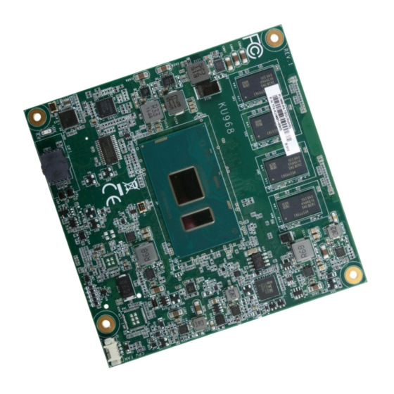
- Page 1 KU968 COM Express Compact Module User’s Manual A-456-M-2007 Chapter 1 Introduction www.dfi.com...
-
Page 2: Copyright
Copyright FCC and DOC Statement on Class B This publication contains information that is protected by copyright. No part of it may be re- This equipment has been tested and found to comply with the limits for a Class B digital produced in any form or by any means or used to make any transformation/adaptation without device, pursuant to Part 15 of the FCC rules. -
Page 3: Table Of Contents
Table of Contents Installing KU968 onto a Carrier Board ..........22 Installing the COM Express Debug Card ..........24 Chapter 4 - BIOS Setup ..............26 Copyright ......................2 Overview ....................... 26 Insyde BIOS Setup Utility ................ 27 Trademarks ......................2 Main ...................... -
Page 4: Warranty
Warranty Static Electricity Precautions 1. Warranty does not cover damages or failures that arised from misuse of the product, It is quite easy to inadvertently damage your PC, system board, components or devices even inability to use the product, unauthorized replacement or alteration of components and before installing them in your system unit. -
Page 5: About The Package
About the Package The package contains the following items. If any of these items are missing or damaged, please contact your dealer or sales representative for assistance. • One KU968 board • One heat sink (Height: 23.8mm) Optional Items • COM332-B carrier board kit •... -
Page 6: Chapter 1 - Introduction
Chapter 1 Chapter 1 - Introduction Specifications SYSTEM Processor 7th Generation Intel ® Core Processors, BGA 1356 WATCHDOG Output & System Reset, Programmable via Software from 1 to 255 Seconds TIMER Intel ® Core i7-7600U Processor, Dual Core, 4M Cache, 2.8GHz (3.9GHz), 15W Interval Intel ®... -
Page 7: Features
Chapter 1 Features • Watchdog Timer The Watchdog Timer function allows your application to regularly “clear” the system at the set time interval. If the system hangs or fails to function, it will reset at the set time interval so that your system will continue to operate. -
Page 8: Chapter 2 - Concept
Chapter 2 Chapter 2 - Concept COM Express Module Standards The figure below shows the dimensions of the different types of COM Express modules. KU968 is a COM Express Compact module. The dimension is 95mm x 95mm. Common for all Form Factors Extended only Basic only Compact only... -
Page 9: Specification Comparison Table
® COM.0 Revision 2.1 Module Pin-out - Required and Optional Features C-D Connector. PICMG ® COM.0 Revision 2.1 COM Express Module Base DFI KU968 COM Express Module Base DFI KU968 Specification Type 6 Type 6 Specification Type 6 Type 6... -
Page 10: Chapter 3 - Hardware Installation
Chapter 3 Chapter 3 - Hardware Installation Board Layout IT8528VG Intel Top View BGA 1356 TPM (optional) Intel Chrontel PTN3460 I219LM CH7517 SPI Flash BIOS CPU Fan Standby Power LED Bottom View D110 COM Express Connector C110 B110 COM Express Connector A110 Chapter 3 Hardware Installation www.dfi... -
Page 11: System Memory
Chapter 3 Important: System Memory DDR4 DDR4 DDR4 DDR4 Electrostatic discharge (ESD) can damage your board, processor, disk drives, add-in boards, and other components. Perform installation procedures at an ESD workstation only. If such a station is not available, you can provide some ESD protection by wear- ing an antistatic wrist strap and attaching it to a metal part of the system chassis. -
Page 12: Connectors
Chapter 3 COM Express Connectors Connectors The COM Express connectors are used to interface the KU968 COM Express board to a carrier CPU Fan Connector board. Connect the COM Express connectors (located on the solder side of the board) to the COM Express connectors on the carrier board. -
Page 13: Com Express Connectors
Chapter 3 COM Express Connectors Row A Row B Row A Row B Row C Row D Row C Row D GND (FIXED) GND (FIXED) PCIE_TX4- PCIE_RX4- GND (FIXED) GND (FIXED) GBE0_MDI3- GBE0_ACT# GPO2 TYPE1# TYPE2# GBE0_MDI3+ LPC_FRAME# PCIE_TX3+ PCIE_RX3+ USB_SSRX0- USB_SSTX0- GBE0_LINK100#... -
Page 14: Com Express Connectors Signal Discription
Chapter 3 COM Express Connectors Signals and Descriptions Pin Types Input to the Module Output from the Module I/O Bi-directional input / output signal OD Open drain output AC97/HDA Signals Descriptions Signal Pin# Module Pin Type Pwr Rail / Tolerance KU968 Carrier Board Description... - Page 15 Chapter 3 PCI Express Lanes Signals Descriptions Signal Pin# Module Pin Type Pwr Rail / Tolerance KU968 Carrier Board Description PCIE_TX2+ AC Coupling capacitor O PCIE AC coupled on Module Connect to PCIE device or slot PCI Express Differential Transmit Pairs 2 PCIE_TX2- AC Coupling capacitor PCIE_RX2+...
- Page 16 Chapter 3 PEG Signals Descriptions Signal Pin# Module Pin Type Pwr Rail / Tolerance KU968 Carrier Board Description PEG_TX12+ O PCIE AC coupled on Module PCI Express Graphics transmit differential pairs 12 PEG_TX12- PEG_RX12+ I PCIE AC coupled off Module PCI Express Graphics receive differential pairs 12 PEG_RX12- PEG_TX13+...
- Page 17 Chapter 3 DDI Signals Descriptions Signal Pin# Module Pin Type Pwr Rail / Tolerance KU968 Carrier Board Description DDI2_HPD I CMOS 3.3V / 3.3V PD 1M and Connect to device Hot Plug Detect DDI Hot-Plug Detect Selects the function of DDI2_CTRLCLK_AUX+ and DDI2_CTRLDATA_AUX-. DDI[n]_DDC_AUX_SEL shall be pulled to 3.3V on the Carrier with a 100K Ohm DDI2_DDC_AUX_SEL I CMOS...
- Page 18 Chapter 3 LVDS Signals Descriptions Signal Pin# Module Pin Type Pwr Rail / Tolerance KU968 Carrier Board Description Connect to LVDS connector LVDS Channel A differential pairs LVDS_A0+ O LVDS LVDS Ther LVDS flat panel differential pairs (LVDS_A[0:3]+/-, LVDS_B[0:3]+/-. LVDS_A_CK+/-, LVDS_A0- LVDS_B_CK+/-) shall have 100 terminations across the pairs at the destination.
- Page 19 Chapter 3 Hardware Installation THRMTRIP# O CMOS 3.3V / 3.3V PU 10K to 3.3V Active low output indicating that the CPU has entered thermal shutdown. www.dfi.com SMB_CK I/O OD CMOS 3.3V Suspend/3.3V PU 2.2K to 3V3_DU_EC System Management Bus bidirectional clock line.
- Page 20 Chapter 3 Power and System Management Signals Descriptions Signal Pin# Module Pin Type Pwr Rail / Tolerance KU968 Carrier Board Description Sleep button. Low active signal used by the ACPI operating system to bring the SLEEP# B103 I OD CMOS 3.3V Suspend/12V PU 10K to 3V3_DU system to sleep state or to wake it up again.
-
Page 21: Standby Power Led
Chapter 3 Standby Power LED Cooling Option Heat Sink Note: The system board used in the following illustrations may not resemble the actual board. These illustrations are for reference only. Top View of the Heat Sink Standby Power LED This LED will be lit when the system is in standby mode. Bottom View of the Heat Sink •... -
Page 22: Installing Ku968 Onto A Carrier Board
Chapter 3 2. Press KU968 down firmly to seat it in the COM Express connectors of the carrier board. Installing KU968 onto a Carrier Board Important: The carrier board (COM332-B) and COM Express module used in this section are for reference purpose only and may not resemble you carrier board and the acutal KU968 module. - Page 23 Chapter 3 3. Use the provided mounting screws to secure KU968 with heat sink to the carrie board. The photo below shows the locations of the long mounting screws. Long screws Chapter 3 Hardware Installation www.dfi .com...
-
Page 24: Installing The Com Express Debug Card
Chapter 3 Installing the COM Express Debug Card (Optional) 2. Connect the COMe-DEBUG card to COMe-LINK1 via a cable. COMe-DEBUG Note: The system board used in the following illustrations may not resemble the actual board. These illustrations are for reference only. Code Review Port 80 Display Control... - Page 25 Chapter 3 3. Use the provided screws to fix the COMe-LINK1 debug card onto the carrier board. Screws COMe-LINK1 Carrier Board COMe-DEBUG 4. Then use the instructions from the previous section to install SU968 and heat sink on the top of the COMe-LINK1 debug card. KU968 COMe-LINK1 Carrier Board...
-
Page 26: Chapter 4 - Bios Setup
Chapter 4 Chapter 4 - BIOS Setup Legends Overview KEYs Function The BIOS is a program that takes care of the basic level of communication between the CPU and peripherals. It contains codes for various advanced features found in this system board. Right and Left Arrows Moves the highlight left or right to select a menu The BIOS allows you to configure the system and save the configuration in a battery-backed... -
Page 27: Insyde Bios Setup Utility
Chapter 4 Insyde BIOS Setup Utility Advanced The Advanced menu allows you to configure your system for basic operation. Some entries are Main defaults required by the system board, while others, if enabled, will improve the performance of your system or let you set some features according to your preference. The Main menu is the first screen that you will see when you enter the BIOS Setup Utility. - Page 28 Chapter 4 ACPI Configuration Note: Under "Dual Boot Type" or "UEFI Boot Type" mode, if "Quiet Boot" is set to This section is used to configure the system ACPI parameters. enabled, "BGRT Logo" field will appear for configuration. Refer to the "Boot" menu in this chapter for more information.
- Page 29 Chapter 4 CPU Configuration Video Configuration This section is used to configure the CPU. This section configures the video settings. InsydeH2O Setup Utility Rev. 5.0 InsydeH2O Setup Utility Rev. 5.0 Advanced Advanced Initial priority: Video Confi guration Allows more than two fre- AUTO: PEG ->...
- Page 30 Chapter 4 Audio Configuration InsydeH2O Setup Utility Rev. 5.0 Advanced This section is used to configure the audio settings. Choose display device Video Confi guration combination Primary Display <Auto> Internal Graphics Device <Auto> InsydeH2O Setup Utility Rev. 5.0 Boot display <DP1+VGA>...
- Page 31 Chapter 4 USB Configuration SATA Configuration This section is used to configure the parameters of the USB device. This section is designed to select the SATA controller and the type of hard disk drive which are installed in your system unit. InsydeH2O Setup Utility Rev.
- Page 32 Chapter 4 PCI Express Configuration PCI Express Root Port 1/2/3/4/6/9/10/11 This section configures settings relevant to PCI Express root ports. This field is used to enable or disable the PCI Express Root Port. InsydeH2O Setup Utility Rev. 5.0 PCIe Speed Advanced PCI Express Root Port 1 Select the speed of the PCI Express Root Port: Auto, Gen1, Gen2 or Gen3.
- Page 33 Chapter 4 ME Configuration MEBX Configuration This section configures settings relevant to flash ME region. Configure Intel Active Management Technology (Intel AMT) in the Intel Management Engine ® ® ® BIOS Extension (MEBX) section. Please refer to Chapter 6 for more information. InsydeH2O Setup Utility Rev.
- Page 34 Chapter 4 Active Management Technology Support Debug Configuration The section allows users to enable or disable the Intel Active Management Technology (Intel This section configures debug setting. ® ® AMT). Please refer to Chapter 6 for more information. InsydeH2O Setup Utility Rev.
- Page 35 Chapter 4 Device Manager Super IO Configuration The section configures UEFI device with option ROM, such as LAN card, etc. This section configures the system super I/O chip parameters. InsydeH2O Setup Utility Rev. 5.0 Advanced InsydeH2O Setup Utility Rev. 5.0 Advanced Confi...
- Page 36 Chapter 4 PC Health Status Rev. 5.0 InsydeH2O Setup Utility Advanced This section displays the PC health status. F a n S p e e d s e t f r o m COM Port 1 <Enable> 1-100% Base I/O Address <3F8>...
- Page 37 Chapter 4 Console Redirection When Console Serial Redirect is set to enabled, the screen will appear like below: This section configures settings relevant to console redirection. InsydeH2O Setup Utility Rev. 5.0 Advanced InsydeH2O Setup Utility Rev. 5.0 Enable Console Redirec- Console Redirection Setup tion Function Advanced...
- Page 38 Chapter 4 When Use Global Setting is set to disabled, the screen will appear like below: COMA/B InsydeH2O Setup Utility Rev. 5.0 InsydeH2O Setup Utility Rev. 5.0 Advanced Advanced Port Enable <Enabled> Port Enable <Enabled> Use Global Setting <Enabled> Use Global Setting <Disabled>...
-
Page 39: Security
Chapter 4 Security Boot InsydeH2O Setup Utility Rev. 5.0 Main Advanced Security Boot Exit InsydeH2O Setup Utility Rev. 5.0 Main Advanced Security Boot Exit Selects Power-on state for Numlock Numlock <On> When Hidden, don’t ex- Current TPM Device <TPM 2.0 (DTPM)> Boot Type <Dual Boot Type>... -
Page 40: Exit
Chapter 4 Exit PXE Boot to LAN Enable or disable PXE boot to LAN. InsydeH2O Setup Utility Rev. 5.0 USB Boot Main Advanced Security Boot Exit Enable or disable to change USB boot devices boot order. Exit system setup and save your changes. -
Page 41: Updating The Bios
You may refer to how-to-video, How the safety concerns, the BIOS (SPI ROM) chip cannot be removed from this system board to update Insyde BIOS in UEFI mode on DFI products?, at https://www.dfi.com/Knowledge/ and used on another system board of the same model. -
Page 42: Chapter 5 - Supported Software
Please download drivers, utilities and software applications required to enhance the perfor- tion tips then click “Install”. mance of the system board at https://www.dfi.com/DownloadCenter . Intel Chipset Software Installation Utility The Intel Chipset Software Installation Utility is used for updating Windows ®... - Page 43 Chapter 5 Intel Graphics Drivers 3. Go through the readme document for system re- quirements and installation To install the driver, download “KU968 Graphics Driver” zip file at our website. tips then click “Next”. 1. Setup is now ready to install the graphics driver.
- Page 44 Chapter 5 Audio Drivers Intel LAN Drivers To install the driver, download “KU968 Audio Driver” zip file at our website. To install the driver, download “KU968 LAN Driver” zip file at our website. 1. Setup is ready to install the 1.
- Page 45 Chapter 5 Intel Management Engine Drivers 4. Click “Install” to begin the installation. To install the driver, download “KU968 MEI Driver” zip file at our website. 1. Setup is ready to install the driver. Click “Next”. 5. The step displays the installing status in the prog- ress.
- Page 46 Chapter 5 Intel Rapid Storage Technology 3. Click “Next” to install to the default folder, or click “Change” to choose another The Intel Rapid Storage Technology is a utility that allows you to monitor the current status destination folder. of the SATA drives. It enables enhanced performance and power management for the storage subsystem.
- Page 47 Chapter 5 3. Go through the readme 6. Click “Yes, I want to restart document to view system this computer now” to requirements and installa- complete the installation tion information then click and then click “Finish”. “Next”. 4. Click “Next” to install to the default folder or click “Change to choose another destination folder”.
- Page 48 Chapter 5 Adobe Acrobat Reader 9.3 3. Setup is now installing the driver. To install the reader, download “KU968 Driver Package” iso file at our website. Click “Adobe Acrobat Reader 9.3”. 1. Click “Next” to install or click “Change Destination Folder”...
- Page 49 Chapter 5 SIO Driver 3. Read the file information then click “Next”. To install the driver, download “KU968 SIO Driver” zip file at our website. 1. Setup is ready to install the driver. Click “Next”. 4. Setup is ready to install the driver. Click “Next”.
- Page 50 Chapter 5 5. Setup is now installing the driver. 6. Click “Finish”. Chapter 5 Supported Software www.dfi .com...
-
Page 51: Chapter 6 - Raid
Chapter 6 Chapter 6 - RAID Settings The system board allows configuring RAID on Serial ATA drives. It supports RAID 0, RAID 1, To enable the RAID function, the following settings are required. and RAID 5. 1. Connect the Serial ATA drives. RAID Levels 2. - Page 52 Chapter 6 Step 3: Create a RAID Volume Step 3-1: Create a RAID Volume if the boot type is UEFI 1. When the Intel RST option ROM status screen displays during POST, press <Ctrl> and If the boot type is set to UEFI, RAID volume creation will be different. Please use the following ®...
- Page 53 Chapter 6 Step 4: Install the Intel Rapid Storage Technology Utility The Intel Rapid Storage Technology Utility can be installed from within Windows. It allows RAID volume management (create, delete, migrate) from within the operating system. It will also display useful SATA device and RAID volume information. The user interface, tray icon service and monitor service allow you to monitor the current status of the RAID volume and/ or SATA drives.
-
Page 54: Chapter 7 - Intel Amt Settings
Chapter 7 Chapter 7 - Intel AMT Settings Enable Intel AMT in the Insyde BIOS ® Overview 1. Power-on the system then press <Del> to enter the main menu of the Insyde BIOS. Intel Active Management Technology (Intel ® AMT) combines hardware and software solution to 2. - Page 55 Chapter 7 4. In the Exit menu, select Exit Saving Changes then select Yes and press Enter. Enable Intel AMT in the Intel Management Engine BIOS ® ® Extension (MEBX) Screen InsydeH2O Setup Utility Rev. 5.0 1. After the system reboots, press <Del> to enter the main menu of the Insyde BIOS. Main Advanced Security...
- Page 56 Chapter 7 4. Select MEBx Login and press Enter. You will be prompted for a password. The default 6. You will be asked to verify the new password. Enter the same new password in the space password is “admin”. Enter the default password in the space provided under Intel(R) ME provided under Verify Password then press Enter.
- Page 57 Chapter 7 8. If you want to change ME password, select Change ME Password then press Enter. 10. You will be asked to verify the new password. Enter the same new password in the space Enter the current password in the space provided under Intel(R) ME Password then press provided under Verify Password then press Enter.
- Page 58 Chapter 7 Press Esc until you return to the Main Menu. Select Intel(R) AMT Configuration then In the Intel(R) AMT Configuration menu, select SOL/Storage Redirection/KVM press Enter. then press Enter. Intel(R) Management Engine BIOS Extension v11.0.0.0010/Intel(R) ME v11.8.50.3434 Intel(R) Management Engine BIOS Extension v11.0.0.0010/Intel(R) ME v11.8.50.3434 Copyright(C) 2003-16 Intel Corporation.
- Page 59 Chapter 7 Select SOL then press Enter. Select Enabled or Disabled then press Enter. Select KVM Feature Selection then press Enter. Select Enabled or Disabled then press Enter. Intel(R) Management Engine BIOS Extension v11.0.0.0010/Intel(R) ME v11.8.50.3434 Intel(R) Management Engine BIOS Extension v11.0.0.0010/Intel(R) ME v11.8.50.3434 Copyright(C) 2003-16 Intel Corporation.
- Page 60 Chapter 7 In the User Consent menu, select User Opt-in then press Enter. Select NONE or KVM Press Esc until you return to the Intel(R) AMT Configuration menu. Select Password or ALL then press Enter. Policy then press Enter. You may choose to use a password only during setup and configuration or to use a pass- word anytime the system is being accessed.
- Page 61 Chapter 7 In the Intel(R) ME Network Setup menu, select Intel(R) ME Network Name Set- Select Domain Name then press Enter. Enter the computer’s domain name then press tings then press Enter. Enter. Intel(R) Management Engine BIOS Extension v11.0.0.0010/Intel(R) ME v11.8.50.3434 Intel(R) Management Engine BIOS Extension v11.0.0.0010/Intel(R) ME v11.8.50.3434 Copyright(C) 2003-16 Intel Corporation.
- Page 62 Chapter 7 Select Dynamic DNS Update then press Enter. Select Enabled or Disabled then press Select TTL then press Enter. Enter value then press Enter. Enter. If Dynamic DNS Update is set to Enabled, Periodic Update Interval and TTL fields will show up. Intel(R) Management Engine BIOS Extension v11.0.0.0010/Intel(R) ME v11.8.50.3434 Intel(R) Management Engine BIOS Extension v11.0.0.0010/Intel(R) ME v11.8.50.3434 Copyright(C) 2003-16 Intel Corporation.
- Page 63 Chapter 7 In the Wired LAN IPV4 Configuration menu, select DHCP Mode then press Enter. Select Subnet Mask Address then press Enter. Enter address then press Enter. Select Enabled or Disabled then press Enter. If set to Disabled, IPV4 Address, Subnet Mask Address, Default Gateway Address, Preferred DNS Address and Alternate DNS Address will show up.
- Page 64 Chapter 7 Select Preferred DNS Address then press Enter. Enter address then press Enter. Press Esc until you return to the Intel(R) AMT Configuration menu. If you want to activate the current network settings and open the ME network inferface, select Activate Network Access, press Enter, then press Y.
- Page 65 Chapter 7 In the Intel(R) AMT Configuration menu, select Remote Setup And Configuration In the Intel(R) Remote Setup And Configuration menu, select Provisioning Re- then press Enter. cord then press Enter. Intel(R) Management Engine BIOS Extension v11.0.0.0010/Intel(R) ME v11.8.50.3434 Intel(R) Management Engine BIOS Extension v11.0.0.0010Intel(R) ME v11.8.50.3434 Copyright(C) 2003-16 Intel Corporation.
- Page 66 Chapter 7 In the Intel(R) Remote Setup And Configuration menu, select Provisioning Press Esc until you return to the Intel(R) Remote Setup And Configuration menu. Server FQDN then press Enter. Enter the FQDN then press Enter. Select TLS PKI then press Enter. Select Remote Configuration ** then press Enter. Select Enabled or Disabled then press Enter.
- Page 67 Chapter 7 In the Intel(R) Remote Configuration menu, select Manage Hashes then press In the Intel(R) AMT Power Control menu, select Idle Timeout then press Enter. Enter. Select the hash name then press Insert to enter custom hash certificate name, Enter the timeout value and press Enter.
Need help?
Do you have a question about the KU968-B4-3965U and is the answer not in the manual?
Questions and answers